engine FORD F650 2015 13.G Manual Online
[x] Cancel search | Manufacturer: FORD, Model Year: 2015, Model line: F650, Model: FORD F650 2015 13.GPages: 384, PDF Size: 4.95 MB
Page 181 of 384
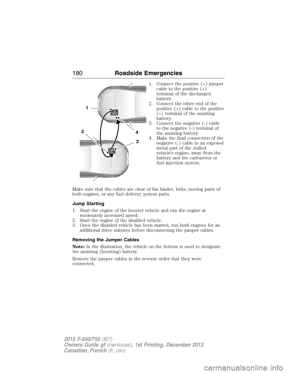
1. Connect the positive (+) jumper
cable to the positive (+)
terminal of the discharged
battery.
2. Connect the other end of the
positive (+) cable to the positive
(+) terminal of the assisting
battery.
3. Connect the negative (-) cable
to the negative (-) terminal of
the assisting battery.
4. Make the final connection of the
negative (-) cable to an exposed
metal part of the stalled
vehicle’s engine, away from the
battery and the carburetor or
fuel injection system.
Make sure that the cables are clear of fan blades, belts, moving parts of
both engines, or any fuel delivery system parts.
Jump Starting
1. Start the engine of the booster vehicle and run the engine at
moderately increased speed.
2. Start the engine of the disabled vehicle.
3. Once the disabled vehicle has been started, run both engines for an
additional three minutes before disconnecting the jumper cables.
Removing the Jumper Cables
Note:In the illustration, the vehicle on the bottom is used to designate
the assisting (boosting) battery.
Remove the jumper cables in the reverse order that they were
connected.
4
2
1
3
180Roadside Emergencies
2015 F-650/750(f67)
Owners Guide gf(ownloose), 1st Printing, December 2013
Canadian_French(fr_can)
Page 182 of 384
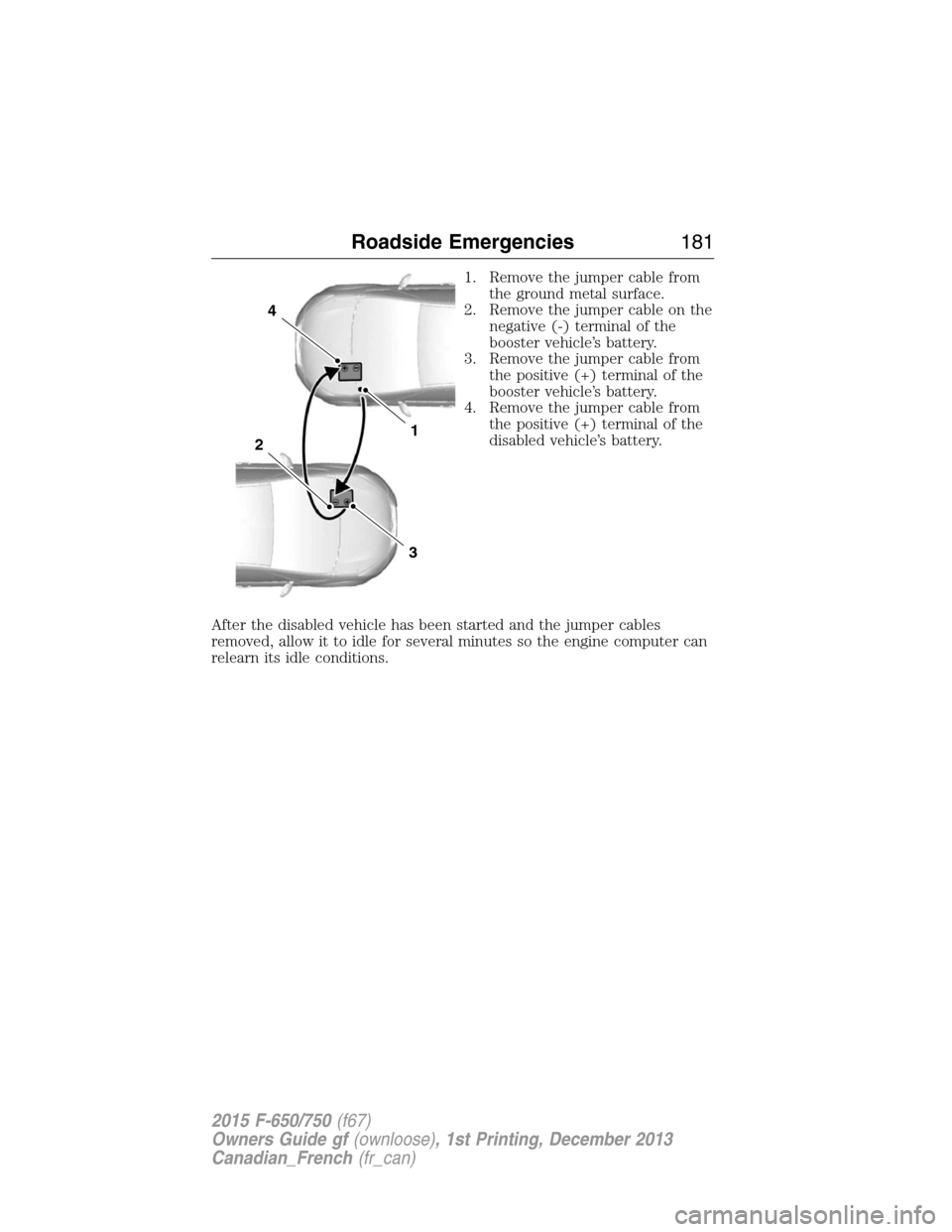
1. Remove the jumper cable from
the ground metal surface.
2. Remove the jumper cable on the
negative (-) terminal of the
booster vehicle’s battery.
3. Remove the jumper cable from
the positive (+) terminal of the
booster vehicle’s battery.
4. Remove the jumper cable from
the positive (+) terminal of the
disabled vehicle’s battery.
After the disabled vehicle has been started and the jumper cables
removed, allow it to idle for several minutes so the engine computer can
relearn its idle conditions.
4
1
3
2
Roadside Emergencies181
2015 F-650/750(f67)
Owners Guide gf(ownloose), 1st Printing, December 2013
Canadian_French(fr_can)
Page 185 of 384
In the case of 1 or 2 above, the consumer must also notify the
manufacturer of the need for the repair of the nonconformity at the
following address:
Ford Motor Company
16800 Executive Plaza Drive
Mail Drop 3NE-B
Dearborn, MI 48126
UTILIZING THE MEDIATION/ARBITRATION PROGRAM (CANADA
ONLY)
For vehicles delivered to authorized Canadian dealers. In those cases
where you continue to feel that the efforts by Ford of Canada and the
authorized dealer to resolve a factory-related vehicle service concern
have been unsatisfactory, Ford of Canada participates in an impartial
third party mediation/arbitration program administered by the Canadian
Motor Vehicle Arbitration Plan (CAMVAP).
The CAMVAP program is a straightforward and relatively speedy
alternative to resolve a disagreement when all other efforts to produce a
settlement have failed. This procedure is without cost to you and is
designed to eliminate the need for lengthy and expensive legal
proceedings.
In the CAMVAP program, impartial third-party arbitrators conduct
hearings at mutually convenient times and places in an informal
environment. These impartial arbitrators review the positions of the
parties, make decisions and, when appropriate, render awards to resolve
disputes. CAMVAP decisions are fast, fair, and final as the arbitrator’s
award is binding on both you and Ford of Canada.
CAMVAP services are available in all Canadian territories and provinces.
For more information, without charge or obligation, call your CAMVAP
Provincial Administrator directly at 1-800-207-0685 or visit
www.camvap.ca.
GETTING ASSISTANCE OUTSIDE THE U.S AND CANADA
Before exporting your vehicle to a foreign country, contact the
appropriate foreign embassy or consulate. These officials can inform you
of local vehicle registration regulations and where to find diesel fuel.
If you cannot find diesel fuel or can only get fuel with an anti-knock
index lower than is recommended for your vehicle, contact a regional
office or owner relations/customer relationship office.
The use of low quality diesel fuel may affect your emissions control
system and may cause engine damage. Ford Motor Company/Ford of
184Customer Assistance
2015 F-650/750(f67)
Owners Guide gf(ownloose), 1st Printing, December 2013
Canadian_French(fr_can)
Page 190 of 384
Fuse/Relay
LocationFuse Amp
RatingProtected Circuits
4 15A Windshield washer relay, Washer pump motor
5 5A Brake warning switch (hydraulic brake
vehicles only)
6 20A Upfitter switches (AUX 1 and AUX 3)
7 15A Brake pressure switches, ABS event relay
8 20A DEF (Urea) line heaters (diesel engine only)
9 20A Ignition switch, Starter cutoff
10 15A Air tank moisture removal valve
11 30A Electric trailer brake
12 20A Passenger compartment fuse box 5 and 21
13 15A Instrument cluster/Gateway module
14 20A Nitrogen oxide sensor (diesel engine only)
15 — Not used
16 5A Bendix® Air ABS
17 — Not used
18 10A Fuel transfer pump
19 15A Powertrain control module power 1 (gasoline
engine only)
20 10A Powertrain control module power 2 (gasoline
engine only)
21 20A Powertrain control module power 3 (gasoline
engine only)
22 20A Powertrain control module power 4 (gasoline
engine only)
23 — Not used
24 10A Powertrain control module keep-alive power
(gasoline engine only)
101 30A Bendix Air ABS relay (Air brake vehicles
only)
Hydraulic brakes module (hydraulic brake
vehicles only)
102 20A Ignition switch
Fuses189
2015 F-650/750(f67)
Owners Guide gf(ownloose), 1st Printing, December 2013
Canadian_French(fr_can)
Page 191 of 384
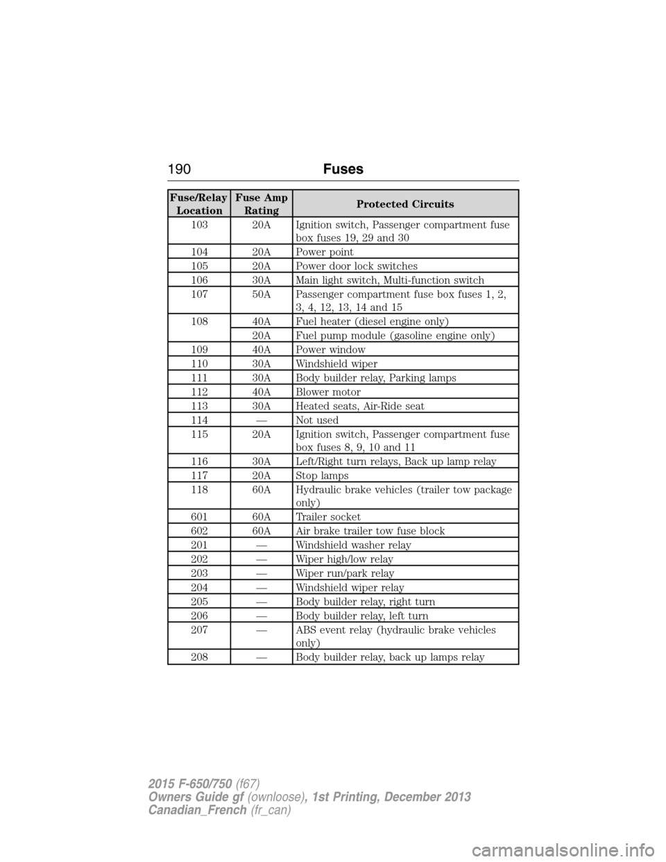
Fuse/Relay
LocationFuse Amp
RatingProtected Circuits
103 20A Ignition switch, Passenger compartment fuse
box fuses 19, 29 and 30
104 20A Power point
105 20A Power door lock switches
106 30A Main light switch, Multi-function switch
107 50A Passenger compartment fuse box fuses 1, 2,
3, 4, 12, 13, 14 and 15
108 40A Fuel heater (diesel engine only)
20A Fuel pump module (gasoline engine only)
109 40A Power window
110 30A Windshield wiper
111 30A Body builder relay, Parking lamps
112 40A Blower motor
113 30A Heated seats, Air-Ride seat
114 — Not used
115 20A Ignition switch, Passenger compartment fuse
box fuses 8, 9, 10 and 11
116 30A Left/Right turn relays, Back up lamp relay
117 20A Stop lamps
118 60A Hydraulic brake vehicles (trailer tow package
only)
601 60A Trailer socket
602 60A Air brake trailer tow fuse block
201 — Windshield washer relay
202 — Wiper high/low relay
203 — Wiper run/park relay
204 — Windshield wiper relay
205 — Body builder relay, right turn
206 — Body builder relay, left turn
207 — ABS event relay (hydraulic brake vehicles
only)
208 — Body builder relay, back up lamps relay
190Fuses
2015 F-650/750(f67)
Owners Guide gf(ownloose), 1st Printing, December 2013
Canadian_French(fr_can)
Page 192 of 384
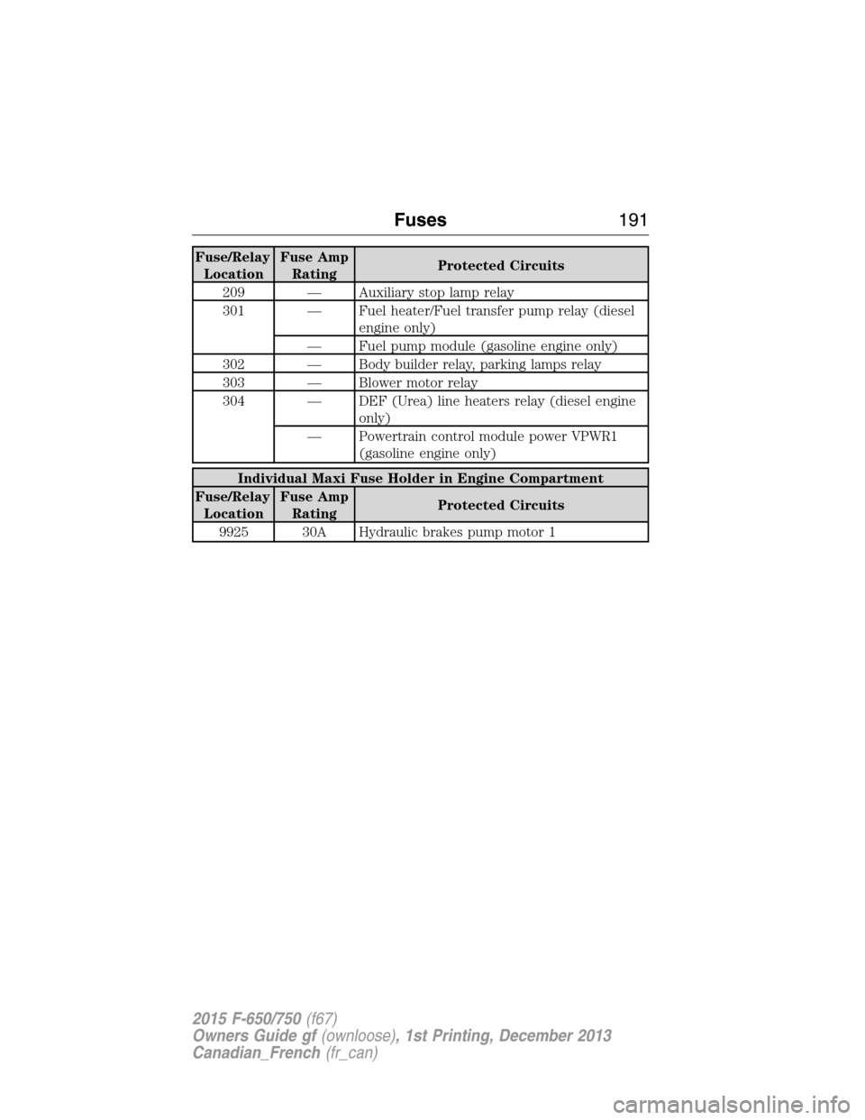
Fuse/Relay
LocationFuse Amp
RatingProtected Circuits
209 — Auxiliary stop lamp relay
301 — Fuel heater/Fuel transfer pump relay (diesel
engine only)
— Fuel pump module (gasoline engine only)
302 — Body builder relay, parking lamps relay
303 — Blower motor relay
304 — DEF (Urea) line heaters relay (diesel engine
only)
— Powertrain control module power VPWR1
(gasoline engine only)
Individual Maxi Fuse Holder in Engine Compartment
Fuse/Relay
LocationFuse Amp
RatingProtected Circuits
9925 30A Hydraulic brakes pump motor 1
Fuses191
2015 F-650/750(f67)
Owners Guide gf(ownloose), 1st Printing, December 2013
Canadian_French(fr_can)
Page 193 of 384
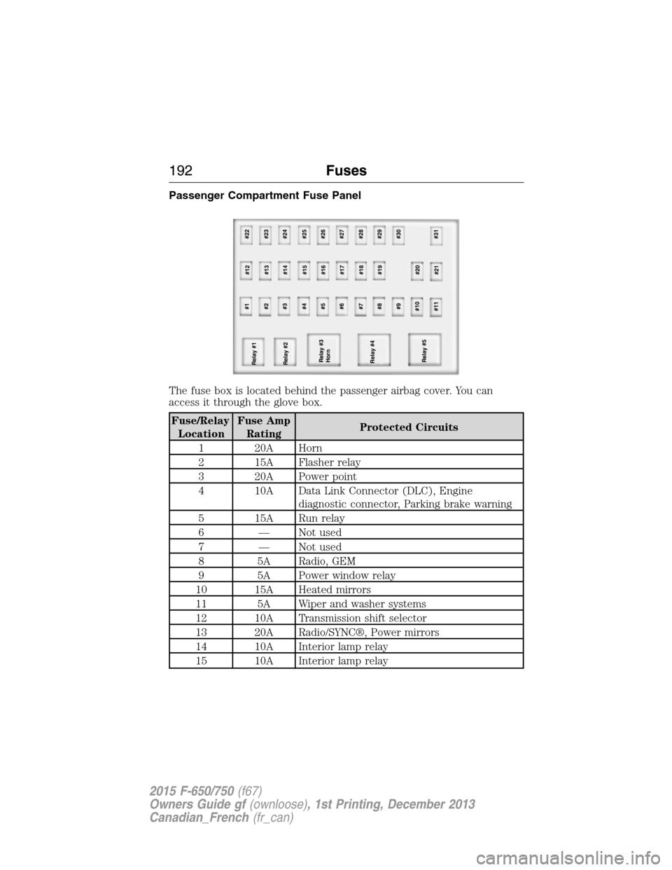
Passenger Compartment Fuse Panel
The fuse box is located behind the passenger airbag cover. You can
access it through the glove box.
Fuse/Relay
LocationFuse Amp
RatingProtected Circuits
1 20A Horn
2 15A Flasher relay
3 20A Power point
4 10A Data Link Connector (DLC), Engine
diagnostic connector, Parking brake warning
5 15A Run relay
6 — Not used
7 — Not used
8 5A Radio, GEM
9 5A Power window relay
10 15A Heated mirrors
11 5A Wiper and washer systems
12 10A Transmission shift selector
13 20A Radio/SYNC®, Power mirrors
14 10A Interior lamp relay
15 10A Interior lamp relay
Relay #2
Relay #3
Horn
Relay #4
Relay #5#1
#12#22
#2
#13#23
#3
#14#24
#4
#15#25
#6
#17#27 #5
#16#26
#7
#18#28
#8
#19#29
#9 #30
#10
#20
#11
#21#31 Relay #1
192Fuses
2015 F-650/750(f67)
Owners Guide gf(ownloose), 1st Printing, December 2013
Canadian_French(fr_can)
Page 194 of 384
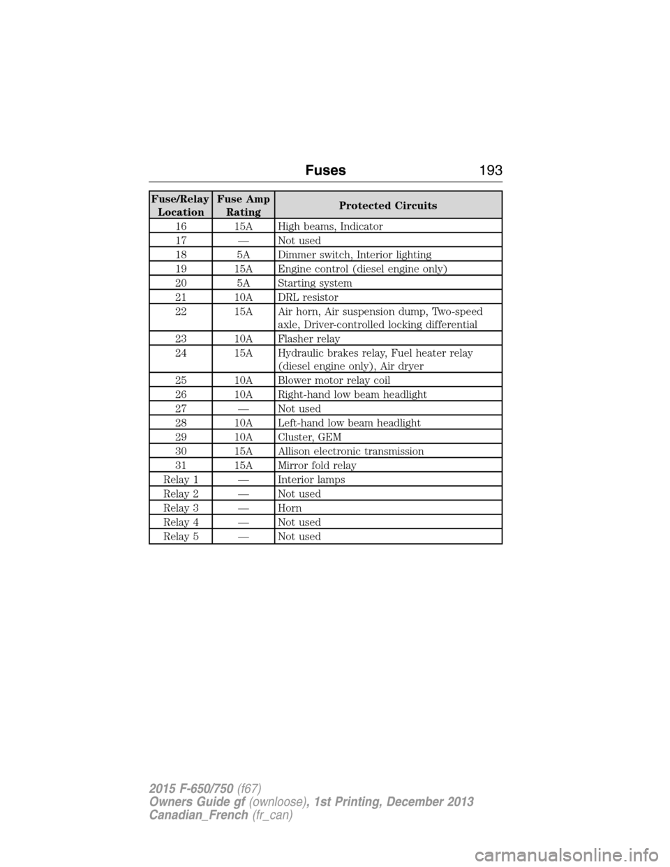
Fuse/Relay
LocationFuse Amp
RatingProtected Circuits
16 15A High beams, Indicator
17 — Not used
18 5A Dimmer switch, Interior lighting
19 15A Engine control (diesel engine only)
20 5A Starting system
21 10A DRL resistor
22 15A Air horn, Air suspension dump, Two-speed
axle, Driver-controlled locking differential
23 10A Flasher relay
24 15A Hydraulic brakes relay, Fuel heater relay
(diesel engine only), Air dryer
25 10A Blower motor relay coil
26 10A Right-hand low beam headlight
27 — Not used
28 10A Left-hand low beam headlight
29 10A Cluster, GEM
30 15A Allison electronic transmission
31 15A Mirror fold relay
Relay 1 — Interior lamps
Relay 2 — Not used
Relay 3 — Horn
Relay 4 — Not used
Relay 5 — Not used
Fuses193
2015 F-650/750(f67)
Owners Guide gf(ownloose), 1st Printing, December 2013
Canadian_French(fr_can)
Page 195 of 384
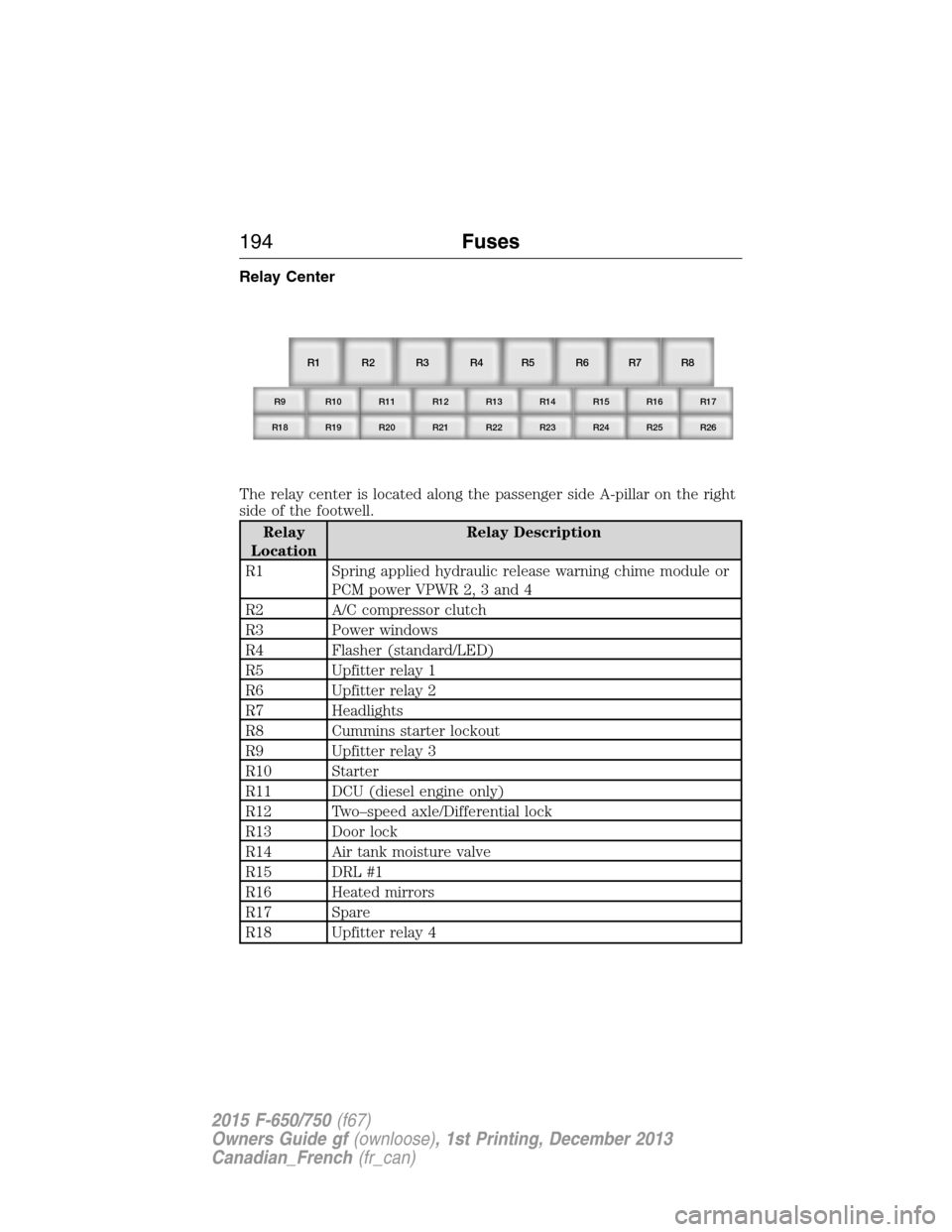
Relay Center
The relay center is located along the passenger side A-pillar on the right
side of the footwell.
Relay
LocationRelay Description
R1 Spring applied hydraulic release warning chime module or
PCM power VPWR 2, 3 and 4
R2 A/C compressor clutch
R3 Power windows
R4 Flasher (standard/LED)
R5 Upfitter relay 1
R6 Upfitter relay 2
R7 Headlights
R8 Cummins starter lockout
R9 Upfitter relay 3
R10 Starter
R11 DCU (diesel engine only)
R12 Two–speed axle/Differential lock
R13 Door lock
R14 Air tank moisture valve
R15 DRL #1
R16 Heated mirrors
R17 Spare
R18 Upfitter relay 4
R1
R9 R10 R11 R12 R13 R14 R15 R16 R17
R18 R19 R20 R21 R22 R23 R24 R25 R26
R2 R3 R4 R5 R6 R7 R8
194Fuses
2015 F-650/750(f67)
Owners Guide gf(ownloose), 1st Printing, December 2013
Canadian_French(fr_can)
Page 196 of 384
Relay
LocationRelay Description
R19 Shift interlock/EPRNDL display
R20 Selective Catalyst Reduction (SCR) system (NOx) (diesel
engine only)
R21 Run
R22 Door unlock
R23 ABS warning indicator
R24 DRL #2
R25 Park lights
R26 Spare
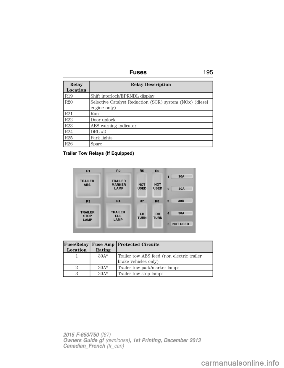
Trailer Tow Relays (If Equipped)
Fuse/Relay
LocationFuse Amp
RatingProtected Circuits
1 30A* Trailer tow ABS feed (non electric trailer
brake vehicles only)
2 30A* Trailer tow park/marker lamps
3 30A* Trailer tow stop lamps
TRAILER
ABS
TRAILER
STOP
LAMPTRAILER
MARKER
LAMP
TRAILER
TA I L
LAMPNOT
USEDNOT
USED
LH
TURNRH
TURN30A
30A
30A
30A
NOT USED
5 4 32 1 R1R2R5
R6
R3R4R7
R8
Fuses195
2015 F-650/750(f67)
Owners Guide gf(ownloose), 1st Printing, December 2013
Canadian_French(fr_can)