check engine FORD F650 2016 13.G Workshop Manual
[x] Cancel search | Manufacturer: FORD, Model Year: 2016, Model line: F650, Model: FORD F650 2016 13.GPages: 379, PDF Size: 4.8 MB
Page 199 of 379
•
Do not mix different colors or types of
coolant in your vehicle. Make sure the
correct coolant is used. Mixing of
engine coolants may harm your
engine ’s cooling system. The use of an
improper coolant may harm engine and
cooling system components and may
void the warranty. Use prediluted
engine coolant meeting the Ford
specification. See Capacities and
Specifications (page 251).
• In case of emergency, a large amount
of water without engine coolant may
be added in order to reach a vehicle
service location. In this instance, the
cooling system must be drained,
chemically cleaned with Motorcraft
Premium Cooling System Flush, and
refilled with engine coolant as soon as
possible. Water alone (without engine
coolant) can cause engine damage
from corrosion, overheating or freezing.
• Do not use alcohol, methanol, brine or
any engine coolants mixed with alcohol
or methanol antifreeze (coolant).
Alcohol and other liquids can cause
engine damage from overheating or
freezing.
• Do not add extra inhibitors or additives
to the coolant. These can be harmful
and compromise the corrosion
protection of the engine coolant.
Add prediluted engine coolant meeting the
Ford specification (Motorcraft Orange
Antifreeze/Coolant Prediluted). See
Capacities and Specifications
(page
251).
Note: Generic coolants marketed for all
makes and models may not meet the Ford
specification and may cause damage to the
cooling system. This damage may void the
warranty. For vehicles with overflow coolant systems
with a non-pressurized cap on the coolant
recovery system, add coolant to the
coolant recovery reservoir when the engine
is cool. Add prediluted engine coolant
(Motorcraft Orange Antifreeze/Coolant
Prediluted) to the FULL COLD level. For all
other vehicles which have a coolant degas
system with a pressurized cap, or if it is
necessary to remove the coolant pressure
relief cap on the radiator of a vehicle with
an overflow system, follow these steps to
add engine coolant.
1. Turn the engine off and let it cool.
2. When the engine is cool, wrap a thick
cloth around the coolant pressure relief
cap on the coolant reservoir (a
translucent plastic bottle). Slowly turn
cap counterclockwise until pressure
begins to release. When you are sure
that all the pressure has been released,
use the cloth to turn it
counterclockwise and remove the cap.
3. Fill the coolant reservoir slowly with prediluted engine coolant to within the
FULL COLD level, or between the MIN
and MAX marks (within the COLD FILL
RANGE), as listed on the engine
coolant reservoir. If you removed the
radiator cap in an overflow system, fill
the radiator until the coolant is visible
and radiator is almost full. If coolant is
added to bring the level within the
COLD FILL RANGE when the engine is
not cold, the system may remain under
filled.
4. Replace the cap. Turn until tightly installed. Cap must be tightly installed
to prevent coolant loss.
Whenever coolant has been added, the
coolant level in the coolant reservoir
should be checked the next few times you
drive the vehicle. If necessary, add enough
prediluted engine coolant to bring the
coolant level to the proper level.
196
F650750 (TBC), enUSA, First Printing Maintenance
Page 200 of 379
If you have to add more than 1.0 quart (1.0
liter) of engine coolant per month, have
your authorized dealer check the engine
cooling system. Your cooling system may
have a leak. Operating an engine with a
low level of coolant can result in engine
overheating and possible engine damage.
Engine and Secondary Cooling
System Refill Procedure
The following procedure should be used
when refilling the engine or secondary
cooling systems after it has been drained
or become extremely low.
1. Before you remove the cap, turn the
engine off and let it cool.
2. When the engine is cool, wrap a thick cloth around the cap. Slowly turn cap
counterclockwise until pressure begins
to release.
3. Step back while the pressure releases.
4. When you are sure that all the pressure
has been released, use the cloth to turn
it counterclockwise and remove the
cap.
5. Slowly add prediluted engine coolant to the coolant reservoir until the
coolant level is within the COLD FILL
RANGE as listed on the reservoir.
6. Reinstall the pressure relief cap.
7. Start and run the engine at 2000 rpm for 2 minutes.
8. Shut engine off, and remove the pressure relief cap as previously
outlined.
9. If required, add prediluted engine coolant to the coolant reservoir until
the coolant level is within the COLD
FILL RANGE as listed on the reservoir. 10.
Engine cooling system: Repeat
Step 5 until the coolant level has
stabilized (is no longer dropping after
each step) AND the upper radiator
hose at the radiator is warm to the
touch (indicating that the engine
thermostat is open and coolant is
flowing through the radiator).
Secondary cooling system: Repeat
Step 5 until the coolant level has
stabilized (is no longer dropping after
each step) AND the lower passenger
side of the secondary radiator is
warm to the touch (indicating
secondary thermostat is open and
coolant is flowing through the entire
system).
11. Reinstall the pressure relief cap. Shut
the engine off and let it cool.
12. Check the coolant level in the reservoir before you drive your vehicle
the next few times (with the engine
cool).
13. If necessary, add prediluted engine coolant to the coolant reservoir until
the coolant level is within the COLD
FILL RANGE as listed on the reservoir.
After any coolant has been added,
check the coolant concentration. See
Adding Engine Coolant
earlier in
the chapter for more information.
Whenever coolant has been added, the
coolant level in the reservoir should be
checked the next few times you drive the
vehicle. If needed, add prediluted engine
coolant to bring the coolant level to the
proper level on the reservoir.
Recycled Engine Coolant
Ford Motor Company does not recommend
the use of recycled engine coolant since a
Ford-approved recycling process is not yet
available.
197
F650750 (TBC), enUSA, First Printing Maintenance
Page 201 of 379
Used engine coolant should be disposed
of in an appropriate manner. Follow your
community
’s regulations and standards
for recycling and disposing of automotive
fluids.
Severe Climates
If you drive in extremely cold climates:
• It may be necessary to have a Ford
authorized dealer increase the coolant
concentration above 50%.
• A coolant concentration of 60% will
provide improved freeze point
protection. Engine coolant
concentrations above 60% will
decrease the overheat protection
characteristics of the engine coolant
and may cause engine damage.
If you drive in extremely hot climates:
• It may be necessary to have a Ford
authorized dealer decrease the coolant
concentration to 40%.
• A coolant concentration of 40% will
provide improved overheat protection.
Engine coolant concentrations below
40% will decrease the freeze and
corrosion protection characteristics of
the engine coolant and may cause
engine damage.
Vehicles driven year-round in non-extreme
climates should use prediluted engine
coolant for optimum cooling system and
engine protection.
Checking Coolant Corrosion
Inhibitor Additive Strength
At specific mileage intervals of 15,000 mi
(24,000 km), as listed in the scheduled
maintenance information chapter, the
coolant corrosion inhibitor additive should
be checked. The optional information
display, if equipped, will also display the
message CHECK COOLANT ADDITIVE at this time. The purpose of checking is to
verify the correct engine coolant
concentration (freeze point protection)
and corrosion inhibitor additive level
(strength) of the coolant for maximum
engine performance and protection.
Three products are available to confirm
the life and health of the coolant, one tool,
a test kit and a coolant inhibitor additive:
198
F650750 (TBC), enUSA, First Printing Maintenance
Page 203 of 379
AUTOMATIC TRANSMISSION
FLUID CHECK
Have an authorized dealer check and
change the transmission fluid and filter at
the correct service interval. See
Scheduled Maintenance (page 314).
Do not use supplemental transmission
fluid additives, treatments or cleaning
agents. The use of these materials may
affect transmission operation and result
in damage to internal transmission
components.
Checking Automatic Transmission
Fluid
Check and change the fluid at the
scheduled intervals. See
Scheduled
Maintenance (page 314). Your
transmission does not consume fluid.
However, the fluid level should be checked
if the transmission is not working properly,
such as if the transmission slips or shifts
slowly or if you notice some sign of fluid
leakage.
Automatic transmission fluid expands
when warmed. To obtain an accurate fluid
check, drive the vehicle until it is at normal
operating temperature, approximately
20 mi (30 km). Verify that the transmission
fluid temperature gauge, located on the
instrument cluster, is within normal range.
1. Drive the vehicle
20 mi (30 km)until it
reaches normal operating temperature.
2. Park the vehicle on a level surface and
engage the parking brake.
3. With the engine running, parking brake
engaged and your foot on the brake
pedal, move the gearshift lever through
all of the gear ranges. Allow sufficient
time for each gear to engage.
4. Latch the gearshift lever in park (P) or neutral (N) and leave the engine
running. 5. Remove the dipstick, wiping it clean
with a clean, dry lint free rag. If
necessary, refer to the Under Hood
Overview in this chapter for the
location of the dipstick.
6. Install the dipstick making sure it is fully
seated in the filler tube.
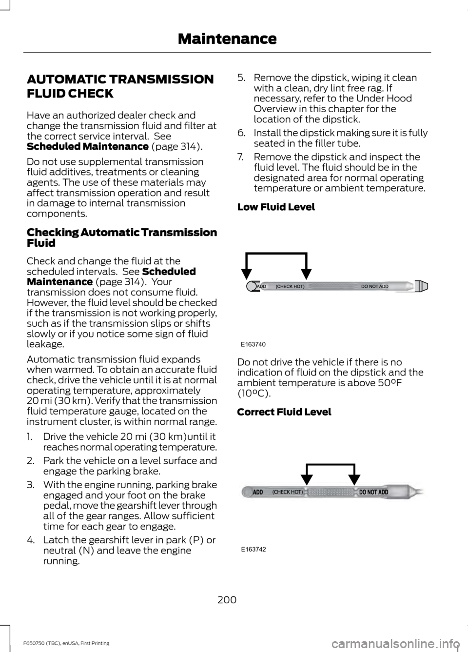
7. Remove the dipstick and inspect the fluid level. The fluid should be in the
designated area for normal operating
temperature or ambient temperature.
Low Fluid Level Do not drive the vehicle if there is no
indication of fluid on the dipstick and the
ambient temperature is above
50°F
(10°C).
Correct Fluid Level 200
F650750 (TBC), enUSA, First Printing MaintenanceE163740 E163742
Page 205 of 379
WARNINGS
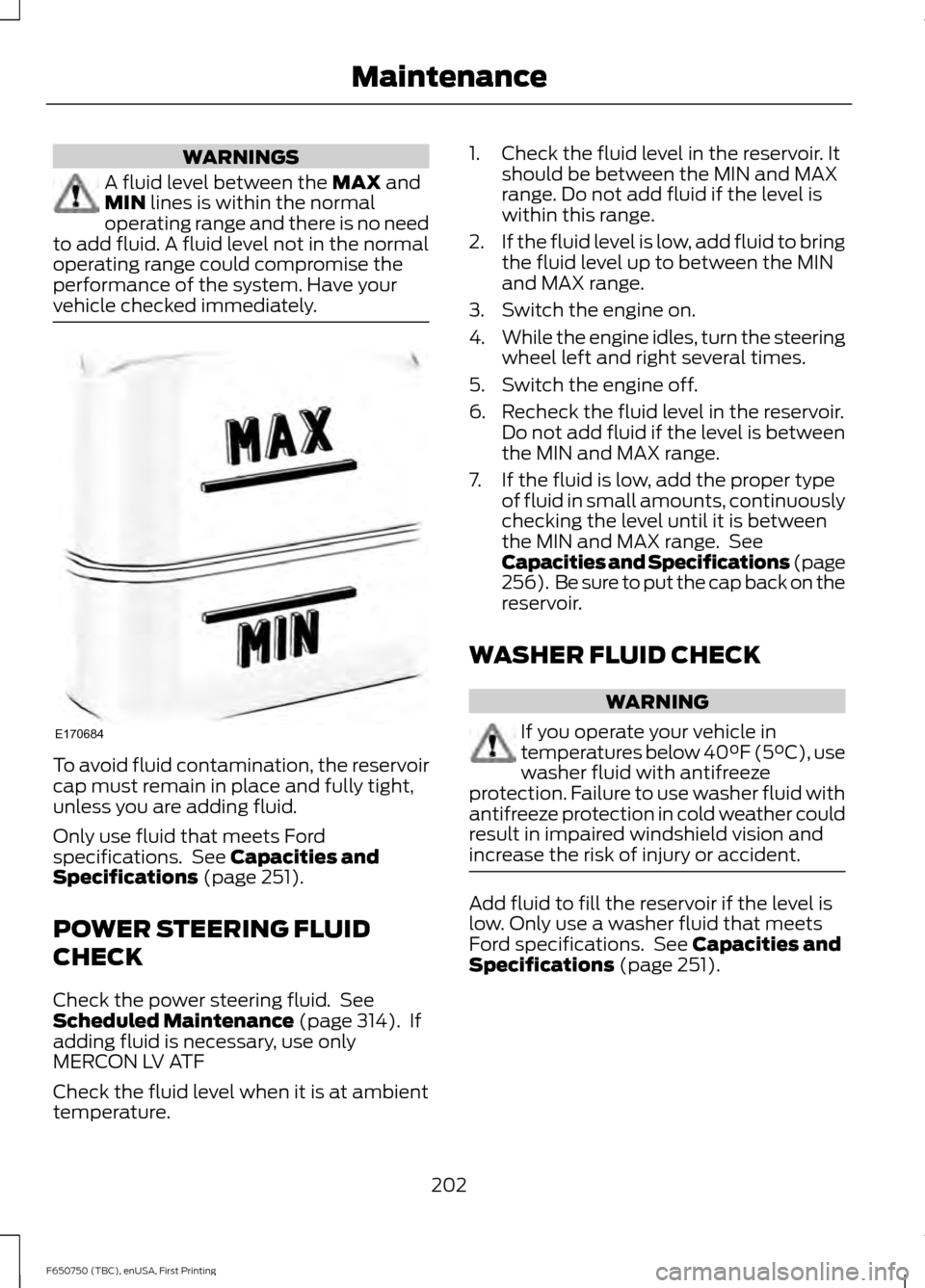
A fluid level between the MAX and
MIN lines is within the normal
operating range and there is no need
to add fluid. A fluid level not in the normal
operating range could compromise the
performance of the system. Have your
vehicle checked immediately. To avoid fluid contamination, the reservoir
cap must remain in place and fully tight,
unless you are adding fluid.
Only use fluid that meets Ford
specifications. See
Capacities and
Specifications (page 251).
POWER STEERING FLUID
CHECK
Check the power steering fluid. See
Scheduled Maintenance
(page 314). If
adding fluid is necessary, use only
MERCON LV ATF
Check the fluid level when it is at ambient
temperature. 1. Check the fluid level in the reservoir. It
should be between the MIN and MAX
range. Do not add fluid if the level is
within this range.
2. If the fluid level is low, add fluid to bring
the fluid level up to between the MIN
and MAX range.
3. Switch the engine on.
4. While the engine idles, turn the steering
wheel left and right several times.
5. Switch the engine off.
6. Recheck the fluid level in the reservoir. Do not add fluid if the level is between
the MIN and MAX range.
7. If the fluid is low, add the proper type of fluid in small amounts, continuously
checking the level until it is between
the MIN and MAX range. See
Capacities and Specifications (page
256). Be sure to put the cap back on the
reservoir.
WASHER FLUID CHECK WARNING
If you operate your vehicle in
temperatures below 40°F (5°C), use
washer fluid with antifreeze
protection. Failure to use washer fluid with
antifreeze protection in cold weather could
result in impaired windshield vision and
increase the risk of injury or accident. Add fluid to fill the reservoir if the level is
low. Only use a washer fluid that meets
Ford specifications. See
Capacities and
Specifications (page 251).
202
F650750 (TBC), enUSA, First Printing MaintenanceE170684
Page 206 of 379
State or local regulations on volatile
organic compounds may restrict the use
of methanol, a common windshield washer
antifreeze additive. Washer fluids
containing non-methanol antifreeze
agents should be used only if they provide
cold weather protection without damaging
the vehicle
’s paint finish, wiper blades or
washer system.
DRAINING THE FUEL FILTER
WATER TRAP - 6.7L DIESEL
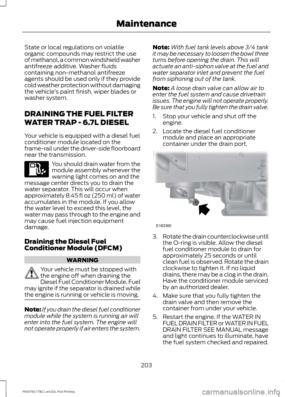
Your vehicle is equipped with a diesel fuel
conditioner module located on the
frame-rail under the driver-side floorboard
near the transmission. You should drain water from the
module assembly whenever the
warning light comes on and the
message center directs you to drain the
water separator. This will occur when
approximately 8.45 fl oz (250 ml) of water
accumulates in the module. If you allow
the water level to exceed this level, the
water may pass through to the engine and
may cause fuel injection equipment
damage.
Draining the Diesel Fuel
Conditioner Module (DFCM) WARNING
Your vehicle must be stopped with
the engine off when draining the
Diesel Fuel Conditioner Module. Fuel
may ignite if the separator is drained while
the engine is running or vehicle is moving. Note:
If you drain the diesel fuel conditioner
module while the system is running air will
enter into the fuel system. The engine will
not operate properly if air enters the system. Note:
With fuel tank levels above 3⁄4 tank
it may be necessary to loosen the bowl three
turns before opening the drain. This will
actuate an anti-siphon valve at the fuel and
water separator inlet and prevent the fuel
from siphoning out of the tank.
Note: A loose drain valve can allow air to
enter the fuel system and cause drivetrain
issues. The engine will not operate properly.
Be sure that you fully tighten the drain valve.
1. Stop your vehicle and shut off the engine.
2. Locate the diesel fuel conditioner module and place an appropriate
container under the drain port. 3.
Rotate the drain counterclockwise until
the O-ring is visible. Allow the diesel
fuel conditioner module to drain for
approximately 25 seconds or until
clean fuel is observed. Rotate the drain
clockwise to tighten it. If no liquid
drains, there may be a clog in the drain.
Have the conditioner module serviced
by an authorized dealer.
4. Make sure that you fully tighten the drain valve and then remove the
container from under your vehicle.
5. Restart the engine. If the WATER IN FUEL DRAIN FILTER or WATER IN FUEL
DRAIN FILTER SEE MANUAL message
and light continues to illuminate, have
the fuel system checked and repaired.
203
F650750 (TBC), enUSA, First Printing Maintenance E163360
Page 215 of 379
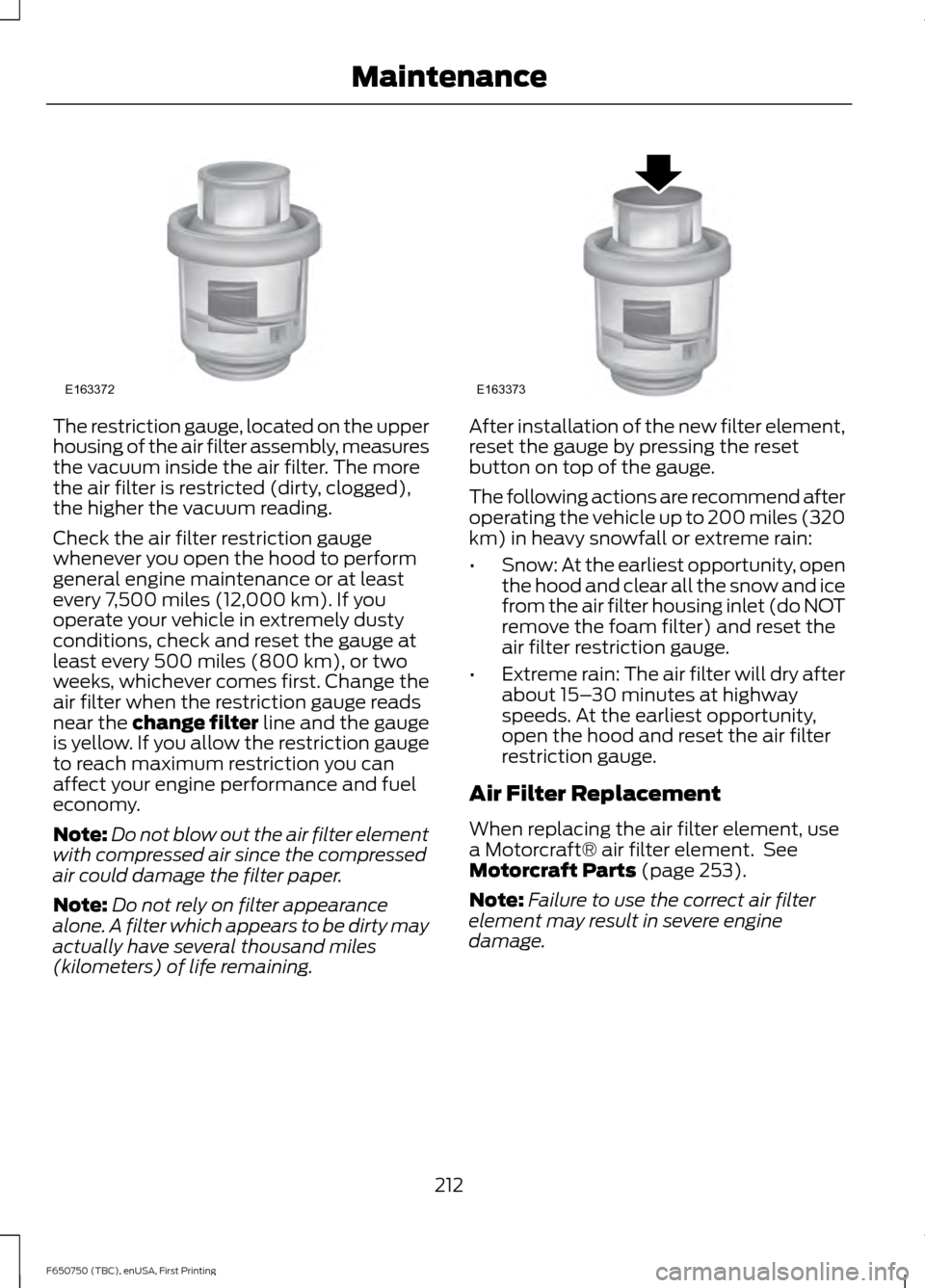
The restriction gauge, located on the upper
housing of the air filter assembly, measures
the vacuum inside the air filter. The more
the air filter is restricted (dirty, clogged),
the higher the vacuum reading.
Check the air filter restriction gauge
whenever you open the hood to perform
general engine maintenance or at least
every 7,500 miles (12,000 km). If you
operate your vehicle in extremely dusty
conditions, check and reset the gauge at
least every 500 miles (800 km), or two
weeks, whichever comes first. Change the
air filter when the restriction gauge reads
near the change filter line and the gauge
is yellow. If you allow the restriction gauge
to reach maximum restriction you can
affect your engine performance and fuel
economy.
Note:
Do not blow out the air filter element
with compressed air since the compressed
air could damage the filter paper.
Note: Do not rely on filter appearance
alone. A filter which appears to be dirty may
actually have several thousand miles
(kilometers) of life remaining. After installation of the new filter element,
reset the gauge by pressing the reset
button on top of the gauge.
The following actions are recommend after
operating the vehicle up to 200 miles (320
km) in heavy snowfall or extreme rain:
•
Snow: At the earliest opportunity, open
the hood and clear all the snow and ice
from the air filter housing inlet (do NOT
remove the foam filter) and reset the
air filter restriction gauge.
• Extreme rain: The air filter will dry after
about 15– 30 minutes at highway
speeds. At the earliest opportunity,
open the hood and reset the air filter
restriction gauge.
Air Filter Replacement
When replacing the air filter element, use
a Motorcraft® air filter element. See
Motorcraft Parts (page 253).
Note: Failure to use the correct air filter
element may result in severe engine
damage.
212
F650750 (TBC), enUSA, First Printing MaintenanceE163372 E163373
Page 221 of 379
Make sure to clean all dust and debris out
of the pipes and couplings with a clean,
damp rag before reassembly.
Chassis-mounted Charge Air
Cooler
Visually inspect the core assembly for
debris and clogging of external fins with
the engine off.
Before engine operation, remove any debris
blocking the core.
•
Turbocharger-to-charge air cooler.
• Charge air cooler-to-intake manifold
pipe.
• Mounting bracket.
• Chassis-mounted charge air cooler
core.
Inspect air intake piping:
• Check for accumulation of salt
deposits (where applicable). If present,
disassemble and clean the complete
air intake piping system. If pitting is
evident on the intake piping, use
Motorcraft Silicone Gasket and Sealant
TA-30 to seal joints against leakage.
• Check for loose hoses and clamps.
• Check for ruptured or collapsed hoses.
• Check air cleaner housing for cracks.
EXHAUST SYSTEM
INSPECTION
Note: If your vehicle is equipped with a
catalytic converter or muffler, do not blend
waste oil with diesel fuel. Operate only on
ultra-low sulfur (less than 15 parts per
million sulfur) diesel fuel with a cetane
value of 45 or higher. If your diesel engine is equipped with a
catalytic converter, it is important to review
the maintenance schedule to make sure
proper functioning of the catalytic
converter. Also, take precautions not to
damage the catalytic converter when
servicing your engine or storing your
vehicle.
BRAKE SYSTEM INSPECTION
WARNING
Always wear a respirator approved
by the National Institute of
Occupational Studies of Health
(NIOSH) or Mine Safety and Appliance
(MSA) during all brake service procedures.
Wear the respirator from removal of the
wheels through assembly.
Never use compressed air or dry brushing
to clean brake parts or assemblies.
Clean brake parts and assemblies in open
air. During assembly, carefully place all
parts on the floor to avoid getting dust in
the air. Use an industrial vacuum cleaner
with a HEPA filter system to clean dust
from the brake drums, backing plates and
other brake parts. After using the vacuum,
remove any remaining dust with a rag
soaked in water and wrung until nearly dry.
Never use compressed air or dry sweeping
to clean the work area. Use an industrial
vacuum cleaner with a HEPA filter system
and rags soaked in water and wrung until
nearly dry. Dispose of used rags with care
to avoid getting dust in the air. Use an
approved respirator when emptying
vacuum cleaners and handling used rags.
Worker clean-up: Wash your hands before
eating, drinking or smoking. Vacuum your
work clothes after use and then launder
them separately, without shaking them, to
prevent fiber dust getting into the air. 218
F650750 (TBC), enUSA, First Printing Maintenance
Page 224 of 379
inspection and keep to instructions
provided by the service manual.
Hydraulic brake systems are
power-assisted. There is a great
reduction in braking capabilities
without engine assist.
• Proper fluid level. The level should be
at the bottom edge of the ring on each
reservoir fill port. Do not fill the master
cylinder to the top of the reservoir. If
fluid level requires attention to
maintain a proper master cylinder level,
this is an indication of either severe
operation (pad wear) or fluid leakage.
A more frequent and thorough brake
inspection is required.
• Brake lines, hoses and fittings. Repair
or replace brake line tubes, hoses or
fittings as required. Inspect these
components every 4,000 mi
(6,000 km) for the following.
• Lines for kinks, dents, corrosion or
rupture.
• Hoses for abrasions, kinks, soft
spots or rupture, collapse, cracks,
twists or loose frame supports.
When replacing a hose, be sure
there is adequate clearance to the
hose to avoid an abrasion to the
new hose.
• All connections for leaks.
Driveline Parking Brake WARNING
Use wheel chocks and exercise
caution when inspecting under the
vehicle. A vehicle roll-away could
result in property damage, personal injury
or death. A qualified technician should adjust the
parking brake and keep to the instructions
in the service manual. AXLE INSPECTION
Front Axle
Maintaining the front axle alignment to
specifications is very important. A qualified
technician should check and maintain the
alignment.
Regular inspections should include:
•
Toe-in inspection and adjustment (if
necessary), particularly with radial
tires.
• Checking for proper tightness of axle
mounting U-bolt nuts, attaching or
mounting bolts and nuts.
• Checking the axle for damage, binding,
worn parts and adequate lubrication.
• Checking the kingpins for excessive
wear. Also, perform this check during
other scheduled maintenance, for
example as tire rotation or service,
wheel bearing service and alignment.
See the workshop manual for proper
procedures.
Toe-in
It is essential to maintain correct toe-in
and tire pressure for optimum tire wear.
Inspecting steer axle tires in the first
3,000– 10,000 mi (5,000– 16,000 km)
generally shows if tires are wearing
normally.
Rapid outside shoulder wear on both tires
indicates too much toe-in.
Rapid inside shoulder wear on both tires
indicates too much toe-out.
In P&D-type service, there can be a
left-to-right steer tire tread life differential
up to 40% depending on routes and other
variables.
221
F650750 (TBC), enUSA, First Printing Maintenance
Page 225 of 379
Follow the tire manufacturer's
recommended cold inflation pressure for
the tire size, load range (ply rating) and
steer axle loading typical for their operation
(each steer axle tire equals ½ steer axle
loading).
Special applications may warrant a setting
based on experience with the type of tire
operating loads and conditions. Radial tires
are more sensitive to toe-in setting than
bias ply tires. Fine tuning school bus
alignment to line-haul truck standards
does not drastically improve tire tread life.
STEERING SYSTEM
INSPECTION
WARNING
Failure to maintain the steering
system in proper condition can cause
reduced steering ability resulting in
property damage, personal injury or death. Note:
Have any steering problems
immediately corrected by a qualified service
technician.
Ask your service technician to examine the
steering mechanism. Only minor
adjustments may be necessary.
Regular inspections should include:
• Checking the tie rod, drag link end
clamp bolts and ball joints for proper
tightness.
• Checking for installation and spread of
cotter pins and tightness of nuts at
both ends of the tie rod and drag link.
• Checking that the pitman arm (steering
arm at steering gear) mounting is tight
and locked. Check system for leaks or
hose chafing. Repair immediately, if
necessary. •
Maintaining proper steering gear and
power steering pump lubricant levels.
• Checking steering column joint bolts
and steering linkage, particularly for
body-to-chassis clearance.
Steering Column Joint Bolts
As a good maintenance practice, check
steering column joint bolt tightness every
60,000 mi (96,000 km) or annually,
whichever occurs first. Do not overtighten
the bolts.
Hydraulic System
Whenever draining and refilling the power
steering's hydraulic system for any reason,
bleed air from the system before returning
the vehicle to service. Failure to bleed the
hydraulic system properly can result in
degradation of power system performance.
Consult an authorized dealer who is aware
of the proper procedures for filling and
bleeding the system.
SUSPENSION SYSTEM
INSPECTION
Note: Do not adjust air suspension height
to any setting other than the specified
setting. Altering the height setting changes
the driveline angle and may result in
unwarrantable component damage, such
as transmission component damage.
Verify drive axle air suspension height and
height control valve performance at engine
oil change intervals.
Periodically check:
• Condition of spring leaves for evidence
of fatigue, bending or breakage.
• Condition of suspension mounting
brackets and bushings.
• Torque rod mounting fasteners for
tightness.
222
F650750 (TBC), enUSA, First Printing Maintenance