steering wheel FORD F650 2017 13.G User Guide
[x] Cancel search | Manufacturer: FORD, Model Year: 2017, Model line: F650, Model: FORD F650 2017 13.GPages: 382, PDF Size: 5.18 MB
Page 118 of 382
Brake-Shift Interlock (If Equipped)
WARNINGS
Do not drive your vehicle until you
verify that the brake lamps are
working.
When doing this procedure, you need
to take the transmission out of park
(P) which means your vehicle can
roll freely. To avoid unwanted vehicle
movement, always fully set the parking
brake prior to doing this procedure. Use
wheels chocks if appropriate. If the parking brake is fully released,
but the brake warning lamp remains
illuminated, the brakes may not be
working properly. Have your vehicle
checked as soon as possible. Your vehicle is equipped with a brake-shift
interlock feature that prevents the
gearshift lever from moving from park (P)
when the ignition is in the 3 (on) position
and the brake pedal is not pressed.
If you cannot move the gearshift lever out
of park (P) position with the ignition in the
4 (on) position and the brake pedal
pressed, a malfunction may have occurred.
It is possible that a fuse has blown or your
vehicle
’s brake lamps are not operating
properly. See
Fuse Specification Chart
(page 161).
If the fuse is not blown and the brake
lamps are working properly, the following
procedure allows you to move the gearshift
lever from park (P):
1. Apply the parking brake. Switch the ignition key to 1 (off), then remove the
key.
2. Move the steering column to the full down and full rearward position
(toward the driver ’s seat).
3. Remove the gearshift lever boot. 4. Place fingers into hole where you
removed the gearshift lever boot and
pull top half of shroud up and forward
to separate it from the lower half of the
shroud. There is a hinge at the forward
edge of the top shroud. Roll the top
half of the shroud upward on the hinge
point to clear the hazard flasher button,
then pull straight rearward toward the
driver ’s seat to remove.
5. Remove the top half of the shroud.
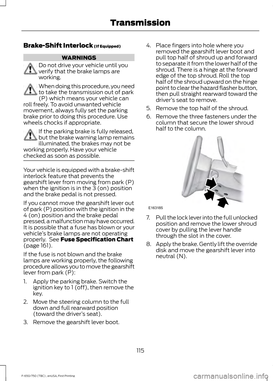
6. Remove the three fasteners under the column that secure the lower shroud
half to the column. 7.
Pull the lock lever into the full unlocked
position and remove the lower shroud
cover by pulling the lever handle
through the slot in the cover.
8. Apply the brake. Gently lift the override
disk and move the gearshift lever into
neutral (N).
115
F-650/750 (TBC) , enUSA, First Printing TransmissionE163185
Page 120 of 382
GENERAL INFORMATION
WARNING
Exceeding these ratings by
overloading can cause component
failure resulting in property damage,
personal injury or death. Fluid Temperature
If the operating temperature exceeds
250°F (121°C), the rate of axle lubrication
oxidation increases and shortens the life
of the lubricant and seals, requiring axle
lubrication changes to become more
frequent to preserve the axle. Do not
consistently run extreme pressure (EP)
lubricants above
250°F (121°C).
Axle Conversions WARNING
When operating a loaded vehicle, the
driver must keep all adjustable axles
on the ground at all times, supporting
their share of the vehicle ’s load. Failure to
do so can overload other axles, tires,
wheels, springs, steering components,
brakes and frames, resulting in early
component failure, loss of vehicle control,
possible property damage and personal
injury. We do not recommend, or approve,
performing axle conversions. However, we
understand that, on occasion, others install
aftermarket add-on axles on the truck
chassis that allow operator control for
weight transfer from other axles (such as
air lift axles). LIMITED SLIP DIFFERENTIAL
(If Equipped) WARNING
If both wheels are not raised off the
ground, the one wheel that is not
raised may pull the vehicle off its
support, possibly resulting in personal
injury. This axle provides added traction on
slippery surfaces, particularly when one
wheel is on a poor traction surface. Under
normal conditions, the limited-slip axle
functions like a standard rear axle. The axle
may exhibit a slight noise or vibration
during tight turns with low vehicle speed.
This is normal behavior and indicates the
axle is working.
Both wheels must be raised off the ground
should it be necessary to operate one
wheel with your vehicle stationary.
ELECTRONIC LOCKING
DIFFERENTIAL
(If Equipped)
Driver-Controlled Locking
Differential
Note: Never use the differential lock at
vehicle speeds above
25 mph (40 km/h).
Some drive axles have a driver-controlled
differential lock. The differential lock can
lock or unlock the differential when your
vehicle is moving or stopped. When extra
traction is required, the differential lock
provides full power to both wheels.
When you lock the differential, your
vehicle ’s turning radius increases
(under-steer).
Take care to avoid sudden accelerations
when both drive wheels are on a slippery
surface.
117
F-650/750 (TBC) , enUSA, First Printing Rear Axle
Page 122 of 382
GENERAL INFORMATION
WARNINGS
Do not drive with your foot resting on
the brake pedal. This results in
abnormally high brake temperatures,
excessive lining wear and increased
stopping distance. Continuous application of the brakes
causes the brakes to overheat,
resulting in temporary loss of braking.
Note:
Occasional brake noise is normal. If
a metal-to-metal, continuous grinding or
continuous squeal sound is present, the
brake linings may be worn-out. Have the
system checked by an authorized dealer. If
your vehicle has continuous vibration or
shudder in the steering wheel while braking,
have it checked by an authorized dealer.
All standard equipment brakes are
self-adjusting. Automatic adjustment,
when required, occurs whenever you apply
and release the brakes during forward or
reverse operation.
Know the required stopping distances for
all driving conditions you may encounter.
For longer brake lining life, take full
advantage of engine braking power when
coming to a stop. See Warning Lamps and
Indicators (page 58).
Wet brakes result in reduced braking
efficiency. Gently press the brake pedal a
few times when driving from a car wash or
standing water to dry the brakes.
If brakes do not grip well:
• Check brake adjustment.
• Check brake linings for excessive wear.
• Check system air pressure on vehicle
equipped with air brakes. •
Let the brakes cool if you have been
using them excessively, as in mountain
driving or after several fast, high-speed
stops.
• If you have been driving through deep
water, gently apply the brakes several
times while your vehicle is moving
slowly.
Brake Over Accelerator
In the event the accelerator pedal
becomes stuck or entrapped, apply steady
and firm pressure to the brake pedal to
slow the vehicle and reduce engine power.
If you experience this condition, apply the
brakes and bring your vehicle to a safe
stop. Move the transmission to park (P),
switch the engine off and apply the parking
brake. Inspect the accelerator pedal for
any interference. If none are found and the
condition persists, have your vehicle towed
to the nearest authorized dealer
Anti-lock Brake System
This system helps you maintain steering
control during emergency stops by keeping
the brakes from locking. This lamp momentarily
illuminates when you turn the
ignition on. If the light does not
illuminate during start up, remains on or
flashes, the system may be disabled. Have
the system checked by an authorized
dealer. If the system is disabled, normal
braking is still effective. If the
brake warning lamp illuminates
when you release the parking brake, have
the system checked by an authorized
dealer.
119
F-650/750 (TBC) , enUSA, First Printing BrakesE209041 E209041
Page 135 of 382
PRINCIPLE OF OPERATION
Cruise control lets you maintain a set
speed without keeping your foot on the
accelerator pedal. You can use cruise
control when your vehicle speed is greater
than 20 mph (30 km/h).
USING CRUISE CONTROL WARNINGS
Do not use cruise control on winding
roads, in heavy traffic or when the
road surface is slippery. This could
result in loss of vehicle control, serious
injury or death. When you are going downhill, your
vehicle speed may increase above
the set speed. The system will not
apply the brakes but a warning displays.
Failure to follow this warning could result
in serious personal injury or death. Note:
Cruise control will disengage if the
vehicle speed decreases more than 10 mph
(16 km/h) below the set speed while driving
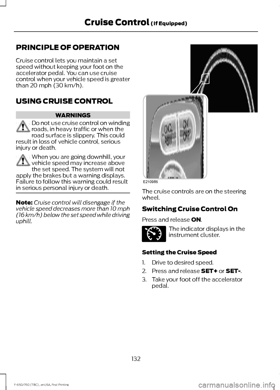
uphill. The cruise controls are on the steering
wheel.
Switching Cruise Control On
Press and release
ON.
The indicator displays in the
instrument cluster.
Setting the Cruise Speed
1. Drive to desired speed.
2. Press and release
SET+ or SET-.
3. Take your foot off the accelerator pedal.
132
F-650/750 (TBC) , enUSA, First Printing Cruise Control
(If Equipped)E210985 E71340
Page 137 of 382
STEERING
To help prevent damage to the power
steering system:
•
Never hold the steering wheel at its
furthest turning points (until it stops)
for more than three to five seconds
when the engine is running.
• Do not operate the vehicle with a low
power steering pump fluid level (below
the MIN mark on the reservoir).
• Some noise is normal during operation.
If excessive, check for low power
steering pump fluid level before
seeking service by your dealer.
• Heavy or uneven efforts may be caused
by low power steering fluid. Check for
low power steering pump fluid level
before seeking service by your dealer.
• Do not fill the power steering pump
reservoir above the MAX mark on the
reservoir, as this may result in leaks
from the reservoir.
If the power steering system breaks down
(or if the engine is turned off), you can
steer the vehicle manually, but it takes
more effort.
Operating the steering system excessively
at an elevated engine RPM (>1200 rpm)
for more than 2 minutes can result in
steering system damage from overheating.
Move the steering wheel to the full left
position then full right position at idle
speed, or stop using the system for 2
minutes to allow the system to cool down.
If the power steering system exhibits heavy
or uneven efforts, check for the following
before seeking service from your dealer:
• An improperly inflated tire.
• Overloading of front suspension.
• Uneven vehicle loading.
• Binding suspension components. If the power steering system wanders or
pulls, check for:
•
An improperly inflated tire.
• Uneven vehicle loading.
• Uneven tire wear.
• Loose or worn suspension
components.
• Loose or worn steering components.
• Improper vehicle alignment.
• High crosswinds.
If any steering components are serviced or
replaced, install new fasteners (many are
coated with thread adhesive or have
prevailing torque features which may not
be re-used). Never re-use a bolt or nut.
Torque fasteners to specifications.
A high crown in the road or high crosswinds
may also make the steering seem to
wander or pull.
134
F-650/750 (TBC) , enUSA, First Printing Driving Aids
Page 139 of 382
AIR SUSPENSION (If Equipped)
Note: Do not operate your vehicle without
air in the suspension springs. Operating your
vehicle without air in the suspension springs
damages the suspension, degrades ride
performance and may cause property
damage.
The air suspension system automatically
adjusts to different loads to maintain a
constant frame height, allows for ease of
vehicle loading, provides improved vehicle
ride, and increased driver comfort.
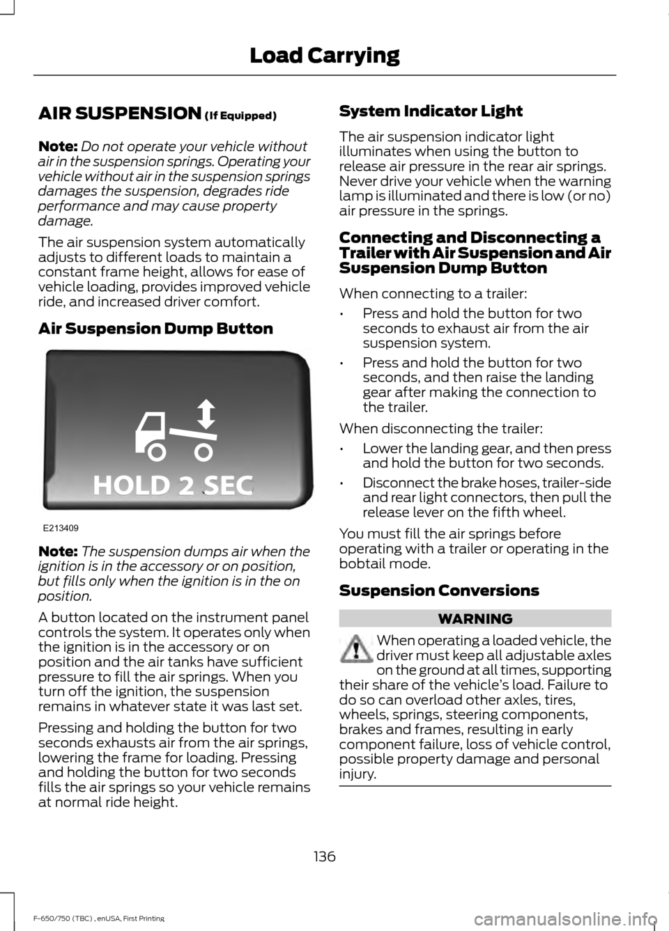
Air Suspension Dump Button Note:
The suspension dumps air when the
ignition is in the accessory or on position,
but fills only when the ignition is in the on
position.
A button located on the instrument panel
controls the system. It operates only when
the ignition is in the accessory or on
position and the air tanks have sufficient
pressure to fill the air springs. When you
turn off the ignition, the suspension
remains in whatever state it was last set.
Pressing and holding the button for two
seconds exhausts air from the air springs,
lowering the frame for loading. Pressing
and holding the button for two seconds
fills the air springs so your vehicle remains
at normal ride height. System Indicator Light
The air suspension indicator light
illuminates when using the button to
release air pressure in the rear air springs.
Never drive your vehicle when the warning
lamp is illuminated and there is low (or no)
air pressure in the springs.
Connecting and Disconnecting a
Trailer with Air Suspension and Air
Suspension Dump Button
When connecting to a trailer:
•
Press and hold the button for two
seconds to exhaust air from the air
suspension system.
• Press and hold the button for two
seconds, and then raise the landing
gear after making the connection to
the trailer.
When disconnecting the trailer:
• Lower the landing gear, and then press
and hold the button for two seconds.
• Disconnect the brake hoses, trailer-side
and rear light connectors, then pull the
release lever on the fifth wheel.
You must fill the air springs before
operating with a trailer or operating in the
bobtail mode.
Suspension Conversions WARNING
When operating a loaded vehicle, the
driver must keep all adjustable axles
on the ground at all times, supporting
their share of the vehicle ’s load. Failure to
do so can overload other axles, tires,
wheels, springs, steering components,
brakes and frames, resulting in early
component failure, loss of vehicle control,
possible property damage and personal
injury. 136
F-650/750 (TBC) , enUSA, First Printing Load CarryingE213409
Page 150 of 382
Operation in Snow and Rain
Vehicle operation in heavy snowfall or
extreme rain conditions may feed
excessive amounts of snow or water into
the air intake system. This could plug the
air filter with snow and may cause the
engine to lose power and possibly shut
down.
We recommend the following actions after
operating your vehicle up to 199 mi
(320 km) in snowfall or extreme rain:
• Snow: At the earliest opportunity, open
the hood and clear all the snow and ice
from the air filter housing inlet (do not
remove the foam filter) and reset the
air filter restriction gauge.
Note: Removal of the foam filter degrades
your vehicle performance during snow and
hot weather conditions.
• Extreme rain: The air filter dries after
about 15– 30 minutes at highway
speeds. At the earliest opportunity,
open the hood and reset the air filter
restriction gauge.
DRIVING THROUGH WATER WARNING
Do not drive through flowing or deep
water as you may lose control of your
vehicle.
Note:
Driving through standing water can
cause vehicle damage.
Note: Engine damage can occur if water
enters the air filter.
Before driving through standing water,
check the depth. Never drive through water
that is higher than the bottom of the wheel
hubs. When driving through standing water, drive
very slowly and do not stop your vehicle.
Your brake performance and traction may
be limited. After driving through water and
as soon as it is safe to do so:
•
Lightly press the brake pedal to dry the
brakes and to check that they work.
• Check that the horn works.
• Check that the exterior lights work.
• Turn the steering wheel to check that
the steering power assist works.
Operation in Standing Water
Ingestion of water into the diesel engine
can result in immediate and severe
damage to the engine. If driving through
water, slow down to avoid splashing water
into the intake. If the engine stalls, and you
suspect ingestion of water into the engine,
do not try to restart the engine. Consult
your dealer for service immediately.
Your fuel tank vents to the atmosphere by
valves on top of the tank and through the
fuel cap. If water reaches the top of the
tank, the valves may pull water into the
fuel tank. Water in the fuel can cause
performance issues and damage the fuel
injection system.
147
F-650/750 (TBC) , enUSA, First Printing Driving HintsE176913
Page 152 of 382
This program is separate from the New
Vehicle Limited Warranty, but the coverage
is concurrent with the powertrain coverage
period of your vehicle.
Canadian customers who require roadside
assistance, call 1-800-665-2006.
Vehicles Sold in Canada: Using
Roadside Assistance
Complete the roadside assistance
identification card and place it in your
wallet for quick reference.
In Canada, this card is found in the
Warranty Guide in the glove compartment
of your vehicle.
Vehicles Sold in Canada: Roadside
Assistance Program Coverage
The service is available 24 hours a day,
seven days a week.
Canadian roadside coverage and benefits
may differ from the U.S. coverage.
For complete program coverage details
you may contact your dealer, you can call
us in Canada at 1-800-665-2006, or visit
our website at www.ford.ca.
HAZARD WARNING FLASHERS
Note:
The hazard warning flashers will
operate when the ignition is in any position
or if the key is not in the ignition. If used
when the engine is not running, the battery
will lose charge. As a result, there may be
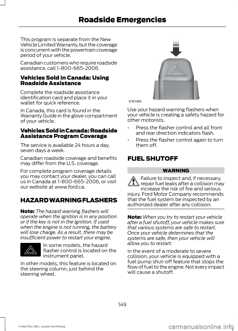
insufficient power to restart your engine. In some models, the hazard
flasher control is located on the
instrument panel.
In other models, this feature is located on
the steering column, just behind the
steering wheel. Use your hazard warning flashers when
your vehicle is creating a safety hazard for
other motorists.
•
Press the flasher control and all front
and rear direction indicators flash.
• Press the flasher control again to turn
them off.
FUEL SHUTOFF WARNING
Failure to inspect and, if necessary,
repair fuel leaks after a collision may
increase the risk of fire and serious
injury. Ford Motor Company recommends
that the fuel system be inspected by an
authorized dealer after any collision. Note:
When you try to restart your vehicle
after a fuel shutoff, your vehicle makes sure
that various systems are safe to restart.
Once your vehicle determines that the
systems are safe, then your vehicle will
allow you to restart.
In the event of a moderate to severe
collision, your vehicle is equipped with a
fuel pump shut-off feature that stops the
flow of fuel to the engine. Not every impact
will cause a shutoff.
149
F-650/750 (TBC) , enUSA, First Printing Roadside EmergenciesE142663 E161463
Page 170 of 382
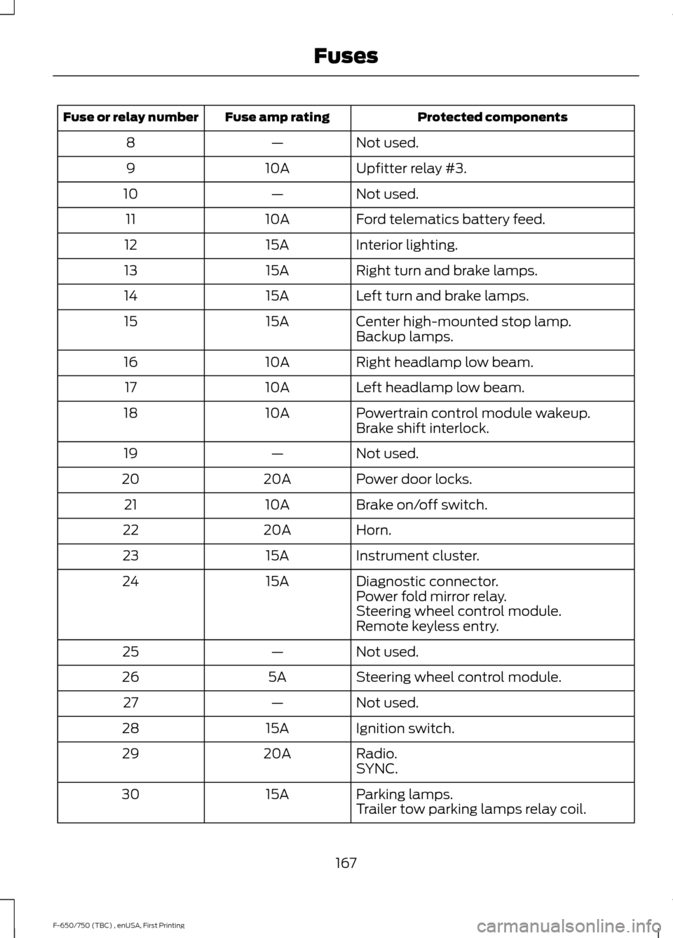
Protected components
Fuse amp rating
Fuse or relay number
Not used.
—
8
Upfitter relay #3.
10A
9
Not used.
—
10
Ford telematics battery feed.
10A
11
Interior lighting.
15A
12
Right turn and brake lamps.
15A
13
Left turn and brake lamps.
15A
14
Center high-mounted stop lamp.
15A
15
Backup lamps.
Right headlamp low beam.
10A
16
Left headlamp low beam.
10A
17
Powertrain control module wakeup.
10A
18
Brake shift interlock.
Not used.
—
19
Power door locks.
20A
20
Brake on/off switch.
10A
21
Horn.
20A
22
Instrument cluster.
15A
23
Diagnostic connector.
15A
24
Power fold mirror relay.
Steering wheel control module.
Remote keyless entry.
Not used.
—
25
Steering wheel control module.
5A
26
Not used.
—
27
Ignition switch.
15A
28
Radio.
20A
29
SYNC.
Parking lamps.
15A
30
Trailer tow parking lamps relay coil.
167
F-650/750 (TBC) , enUSA, First Printing Fuses
Page 174 of 382
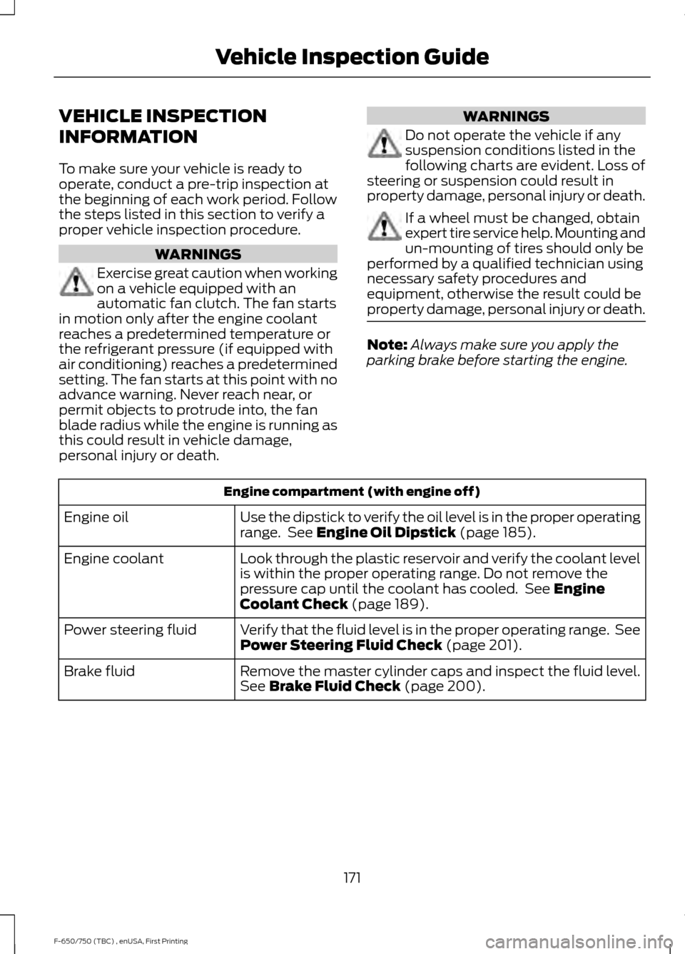
VEHICLE INSPECTION
INFORMATION
To make sure your vehicle is ready to
operate, conduct a pre-trip inspection at
the beginning of each work period. Follow
the steps listed in this section to verify a
proper vehicle inspection procedure.
WARNINGS
Exercise great caution when working
on a vehicle equipped with an
automatic fan clutch. The fan starts
in motion only after the engine coolant
reaches a predetermined temperature or
the refrigerant pressure (if equipped with
air conditioning) reaches a predetermined
setting. The fan starts at this point with no
advance warning. Never reach near, or
permit objects to protrude into, the fan
blade radius while the engine is running as
this could result in vehicle damage,
personal injury or death. WARNINGS
Do not operate the vehicle if any
suspension conditions listed in the
following charts are evident. Loss of
steering or suspension could result in
property damage, personal injury or death. If a wheel must be changed, obtain
expert tire service help. Mounting and
un-mounting of tires should only be
performed by a qualified technician using
necessary safety procedures and
equipment, otherwise the result could be
property damage, personal injury or death. Note:
Always make sure you apply the
parking brake before starting the engine. Engine compartment (with engine off)
Use the dipstick to verify the oil level is in the proper operating
range. See Engine Oil Dipstick (page 185).
Engine oil
Look through the plastic reservoir and verify the coolant level
is within the proper operating range. Do not remove the
pressure cap until the coolant has cooled. See
Engine
Coolant Check (page 189).
Engine coolant
Verify that the fluid level is in the proper operating range. See
Power Steering Fluid Check
(page 201).
Power steering fluid
Remove the master cylinder caps and inspect the fluid level.
See
Brake Fluid Check (page 200).
Brake fluid
171
F-650/750 (TBC) , enUSA, First Printing Vehicle Inspection Guide