check engine FORD F650 2017 13.G Repair Manual
[x] Cancel search | Manufacturer: FORD, Model Year: 2017, Model line: F650, Model: FORD F650 2017 13.GPages: 382, PDF Size: 5.18 MB
Page 205 of 382
DRAINING THE FUEL FILTER
WATER TRAP - 6.7L DIESEL
Your vehicle is equipped with a diesel fuel
conditioner module located on the
frame-rail under the driver-side floorboard
near the transmission.
You should drain water from the
module assembly whenever the
warning light comes on and the
message center directs you to drain the
water separator. This will occur when
approximately 8.45 fl oz (250 ml) of water
accumulates in the module. If you allow
the water level to exceed this level, the
water may pass through to the engine and
may cause fuel injection equipment
damage.
Draining the Diesel Fuel
Conditioner Module (DFCM) WARNING
Your vehicle must be stopped with
the engine off when draining the
Diesel Fuel Conditioner Module. Fuel
may ignite if the separator is drained while
the engine is running or vehicle is moving. Note:
If you drain the diesel fuel conditioner
module while the system is running air will
enter into the fuel system. The engine will
not operate properly if air enters the system.
Note: With fuel tank levels above 3⁄4 tank
it may be necessary to loosen the bowl three
turns before opening the drain. This will
actuate an anti-siphon valve at the fuel and
water separator inlet and prevent the fuel
from siphoning out of the tank.
Note: A loose drain valve can allow air to
enter the fuel system and cause drivetrain
issues. The engine will not operate properly.
Be sure that you fully tighten the drain valve. 1. Stop your vehicle and shut off the
engine.
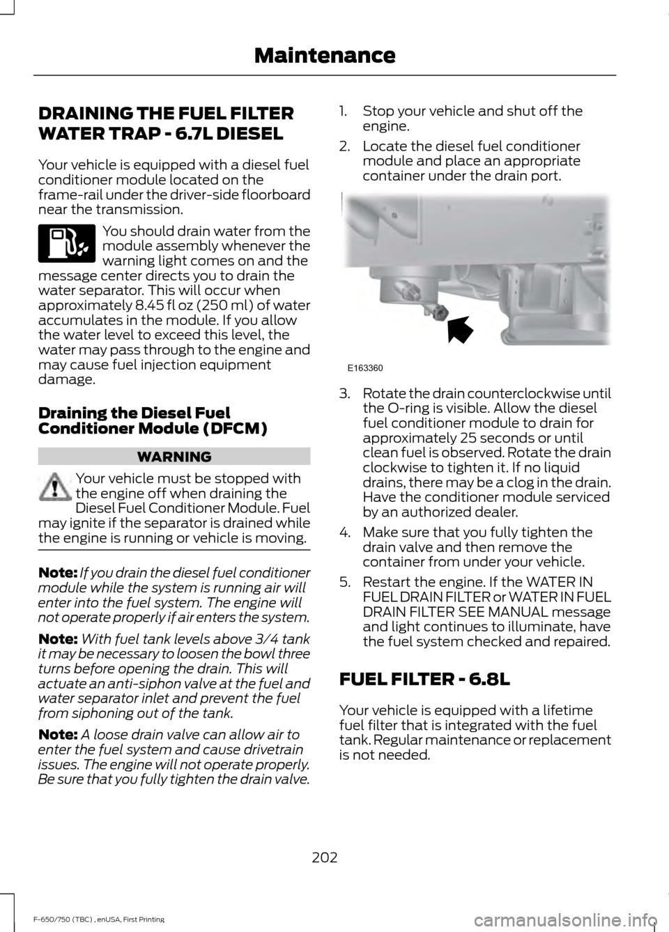
2. Locate the diesel fuel conditioner module and place an appropriate
container under the drain port. 3.
Rotate the drain counterclockwise until
the O-ring is visible. Allow the diesel
fuel conditioner module to drain for
approximately 25 seconds or until
clean fuel is observed. Rotate the drain
clockwise to tighten it. If no liquid
drains, there may be a clog in the drain.
Have the conditioner module serviced
by an authorized dealer.
4. Make sure that you fully tighten the drain valve and then remove the
container from under your vehicle.
5. Restart the engine. If the WATER IN FUEL DRAIN FILTER or WATER IN FUEL
DRAIN FILTER SEE MANUAL message
and light continues to illuminate, have
the fuel system checked and repaired.
FUEL FILTER - 6.8L
Your vehicle is equipped with a lifetime
fuel filter that is integrated with the fuel
tank. Regular maintenance or replacement
is not needed.
202
F-650/750 (TBC) , enUSA, First Printing Maintenance E163360
Page 214 of 382
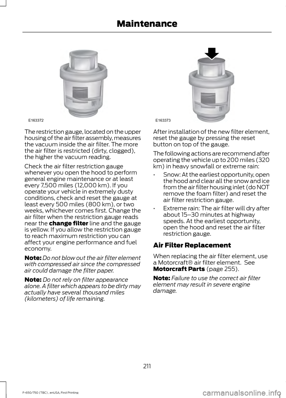
The restriction gauge, located on the upper
housing of the air filter assembly, measures
the vacuum inside the air filter. The more
the air filter is restricted (dirty, clogged),
the higher the vacuum reading.
Check the air filter restriction gauge
whenever you open the hood to perform
general engine maintenance or at least
every 7,500 miles (12,000 km). If you
operate your vehicle in extremely dusty
conditions, check and reset the gauge at
least every 500 miles (800 km), or two
weeks, whichever comes first. Change the
air filter when the restriction gauge reads
near the change filter line and the gauge
is yellow. If you allow the restriction gauge
to reach maximum restriction you can
affect your engine performance and fuel
economy.
Note:
Do not blow out the air filter element
with compressed air since the compressed
air could damage the filter paper.
Note: Do not rely on filter appearance
alone. A filter which appears to be dirty may
actually have several thousand miles
(kilometers) of life remaining. After installation of the new filter element,
reset the gauge by pressing the reset
button on top of the gauge.
The following actions are recommend after
operating the vehicle up to 200 miles (320
km) in heavy snowfall or extreme rain:
•
Snow: At the earliest opportunity, open
the hood and clear all the snow and ice
from the air filter housing inlet (do NOT
remove the foam filter) and reset the
air filter restriction gauge.
• Extreme rain: The air filter will dry after
about 15– 30 minutes at highway
speeds. At the earliest opportunity,
open the hood and reset the air filter
restriction gauge.
Air Filter Replacement
When replacing the air filter element, use
a Motorcraft® air filter element. See
Motorcraft Parts (page 255).
Note: Failure to use the correct air filter
element may result in severe engine
damage.
211
F-650/750 (TBC) , enUSA, First Printing MaintenanceE163372 E163373
Page 221 of 382
In areas where road salt is used,
disassemble the joints of each aluminum
component and inspect for salt build-up
and presence of chlorine that can cause
aluminum particles to flake off and enter
the engine combustion chambers. If
evidence of corrosion is found (usually at
the pipe connections), use a wire brush to
clean the inside of the pipes and inside the
rubber hoses.
If pitting is evident at the joint ends of the
intake pipes, use Motorcraft Silicone
Gasket and Sealant TA-30 to seal the
joints. Make sure no excess material, which
can pull into the engine, is on the inside of
the pipes. If the service condition of the
pipes, hoses or clamps is questionable,
replace the defective part(s).
Make sure to clean all dust and debris out
of the pipes and couplings with a clean,
damp rag before reassembly.
Chassis-mounted Charge Air
Cooler
Visually inspect the core assembly for
debris and clogging of external fins with
the engine off.
Before engine operation, remove any debris
blocking the core.
•
Turbocharger-to-charge air cooler.
• Charge air cooler-to-intake manifold
pipe.
• Mounting bracket.
• Chassis-mounted charge air cooler
core.
Inspect air intake piping:
• Check for accumulation of salt
deposits (where applicable). If present,
disassemble and clean the complete
air intake piping system. If pitting is
evident on the intake piping, use
Motorcraft Silicone Gasket and Sealant
TA-30 to seal joints against leakage.
• Check for loose hoses and clamps. •
Check for ruptured or collapsed hoses.
• Check air cleaner housing for cracks.
EXHAUST SYSTEM
INSPECTION
Note: If your vehicle is equipped with a
catalytic converter or muffler, do not blend
waste oil with diesel fuel. Operate only on
ultra-low sulfur (less than 15 parts per
million sulfur) diesel fuel with a cetane
value of 45 or higher.
If your diesel engine is equipped with a
catalytic converter, it is important to review
the maintenance schedule to make sure
proper functioning of the catalytic
converter. Also, take precautions not to
damage the catalytic converter when
servicing your engine or storing your
vehicle.
218
F-650/750 (TBC) , enUSA, First Printing Maintenance
Page 224 of 382
any air tanks equipped with automatic
moisture ejector valves, as required, to
maintain a dry air system. Contact an
authorized dealer if you are unsure of the
air reservoir locations or the draining
procedure.
Hydraulic Brakes
Establish a regular schedule for periodic
cleaning, lubrication and adjustment
inspection based on vehicle use. Exact
maintenance intervals are difficult to
predetermine due to vehicle applications
and operating conditions. If you are
uncertain of the proper schedule for your
vehicle, contact an authorized dealer.
Regular inspections should include:
•
Checking the brake lining (every service
interval). Establish inspection intervals
that provide for lining replacement
before damage to the disc occurs.
Excessive lining wear may expose the
backing plate to the disc causing
scoring of the disc faces. A qualified
technician should perform this inspection and keep to instructions
provided by the service manual.
Hydraulic brake systems are
power-assisted. There is a great
reduction in braking capabilities
without engine assist.
• Proper fluid level. The level should be
at the bottom edge of the ring on each
reservoir fill port. Do not fill the master
cylinder to the top of the reservoir. If
fluid level requires attention to
maintain a proper master cylinder level,
this is an indication of either severe
operation (pad wear) or fluid leakage.
A more frequent and thorough brake
inspection is required.
• Brake lines, hoses and fittings. Repair
or replace brake line tubes, hoses or
fittings as required. Inspect these
components every 4,000 mi
(6,000 km) for the following.
• Lines for kinks, dents, corrosion or
rupture.
• Hoses for abrasions, kinks, soft
spots or rupture, collapse, cracks,
twists or loose frame supports.
When replacing a hose, be sure
there is adequate clearance to the
hose to avoid an abrasion to the
new hose.
• All connections for leaks.
Driveline Parking Brake WARNING
Use wheel chocks and exercise
caution when inspecting under the
vehicle. A vehicle roll-away could
result in property damage, personal injury
or death. A qualified technician should adjust the
parking brake and keep to the instructions
in the service manual.
221
F-650/750 (TBC) , enUSA, First Printing Maintenance
Page 226 of 382
•
Maintaining proper steering gear and
power steering pump lubricant levels.
• Checking steering column joint bolts
and steering linkage, particularly for
body-to-chassis clearance.
Steering Column Joint Bolts
As a good maintenance practice, check
steering column joint bolt tightness every
60,000 mi (96,000 km) or annually,
whichever occurs first. Do not overtighten
the bolts.
Hydraulic System
Whenever draining and refilling the power
steering's hydraulic system for any reason,
bleed air from the system before returning
the vehicle to service. Failure to bleed the
hydraulic system properly can result in
degradation of power system performance.
Consult an authorized dealer who is aware
of the proper procedures for filling and
bleeding the system.
SUSPENSION SYSTEM
INSPECTION
Note: Do not adjust air suspension height
to any setting other than the specified
setting. Altering the height setting changes
the driveline angle and may result in
unwarrantable component damage, such
as transmission component damage.
Verify drive axle air suspension height and
height control valve performance at engine
oil change intervals.
Periodically check:
• Condition of spring leaves for evidence
of fatigue, bending or breakage.
• Condition of suspension mounting
brackets and bushings.
• Torque rod mounting fasteners for
tightness. •
For proper suspension alignment.
Maintain proper alignment at all times.
• U-bolts. After the chassis has been
operating under load for
1,000 mi
(1,600 km) or six months (whichever
comes first), the U-bolt nuts must be
re-torqued. Re-torque the U-bolt nuts
every
37,000 mi (60,000 km)
thereafter. Clean and lubricate the
U-bolt and nut threads and seats to
make sure a like new condition when
re-torqueing. See
Spring U-Bolt
Check (page 224).
FRAME AND TOW HOOK
INSPECTION
Your vehicle's chassis is manufactured
with frame rails of either HSLA steel or
heat-treated steel. Handle each in a
specific manner to make sure maximum
service life. Consult the service manual or
an authorized dealer before attempting
frame repair or modification.
It is important, particularly on vehicles that
use tow hooks frequently, to inspect the
front and rear tow hooks for damage or a
loose mounting.
REAR AXLE FLUID CHECK
Your rear axle may have an optional
synthetic lubricant that allows the use of
extended service intervals. A tag on the
filler plug identifies the use of the synthetic
lubricant.
Only use a lubricant that meets
manufacturer specifications. Only use a
lubricant that meets manufacturer
specifications. Use of a non-approved rear
axle lubricant may cause internal axle
component damage. See Capacities and
Specifications
(page 258).
223
F-650/750 (TBC) , enUSA, First Printing Maintenance
Page 227 of 382
Checking the Fluid Level
1. Park your vehicle on level ground.
2. Set the parking brake and shift into
position neutral (N) or park (P). Turn
the engine off.
3. Clean any dirt from around the axle filler plug.
4. Remove the filler plug and inspect the lubricant level. It should be at the
bottom of the filler plug opening.
5. Add lubricant, if necessary, through the
filler plug opening.
6. Clean and install the filler plug securely.
Changing the Fluid
Note: Drain the rear axle while the lubricant
is warm.
1. Park your vehicle on level ground.
2. Set the parking brake and shift into position neutral (N) or park (P). Turn
the engine off.
3. Clean any dirt from around the axle filler and drain plugs.
4. Remove the filler and drain plugs. Drain
the lubricant into a suitable container.
Dispose of all used automotive fluids
in a responsible manner following your
local authorized standards.
5. Clean and install the drain plug securely.
6. Add lubricant through the filler plug opening.
7. Clean and install the filler plug securely.
SPRING U-BOLT CHECK
Check and tighten the U-bolt nuts after
your vehicle has been operated under load
for 1,000 mi (1,600 km) or six months,
whichever occurs first. Thereafter, install new U-bolt nuts and
washers every
36,000 mi (58,000 km).
Check and tighten the U-bolt nuts with
your vehicle at curb height and unloaded.
Inspect the U-bolt threads for rust and
debris. Clean the threads if contaminated.
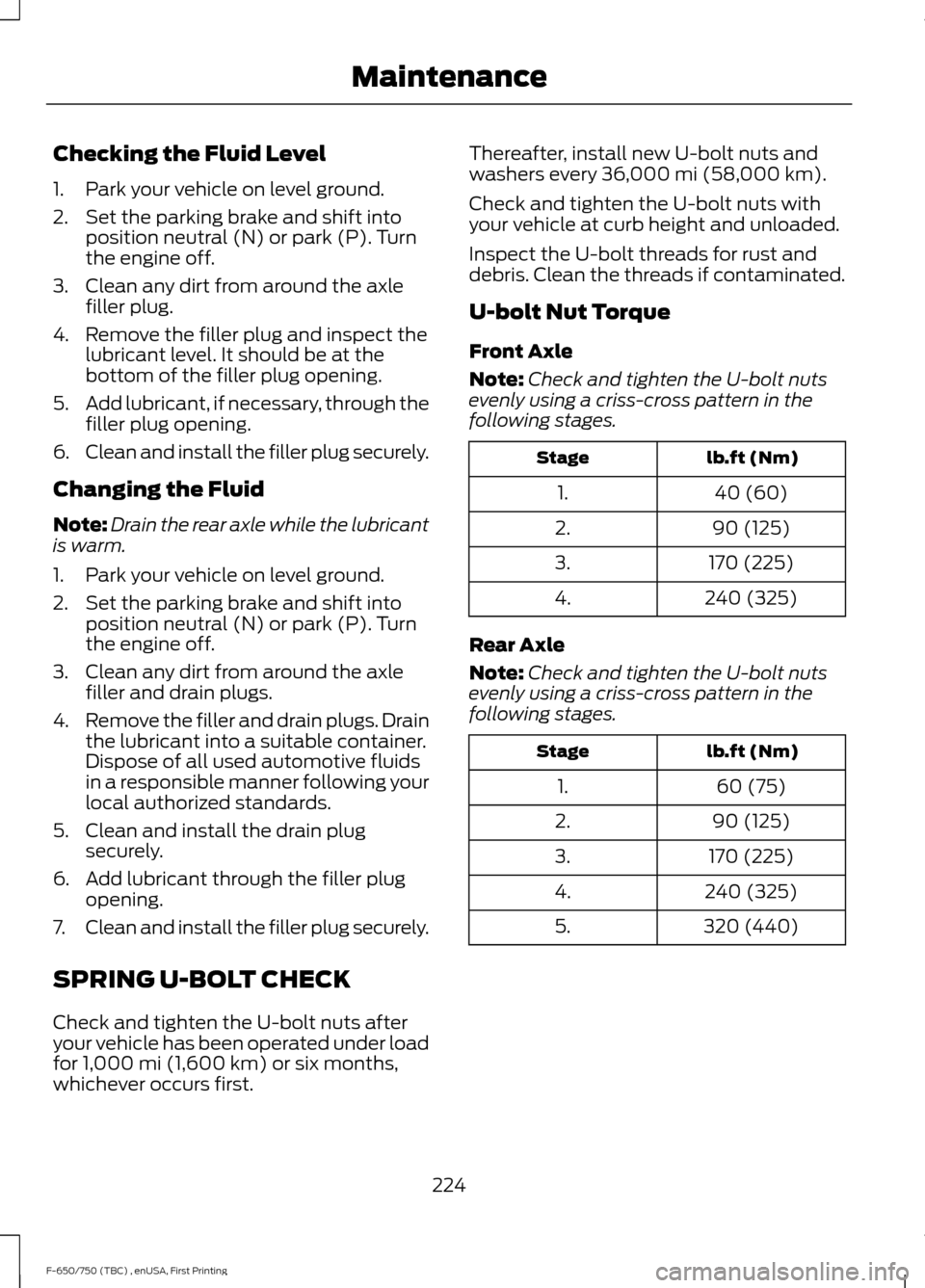
U-bolt Nut Torque
Front Axle
Note: Check and tighten the U-bolt nuts
evenly using a criss-cross pattern in the
following stages. lb.ft (Nm)
Stage
40 (60)
1.
90 (125)
2.
170 (225)
3.
240 (325)
4.
Rear Axle
Note: Check and tighten the U-bolt nuts
evenly using a criss-cross pattern in the
following stages. lb.ft (Nm)
Stage
60 (75)
1.
90 (125)
2.
170 (225)
3.
240 (325)
4.
320 (440)
5.
224
F-650/750 (TBC) , enUSA, First Printing Maintenance
Page 234 of 382
Engine
•
Change the engine oil and filter prior to
storage because used engine oil
contains contaminates which may
cause engine damage.
• Start the engine every 15 days for a
minimum of 15 minutes. Run at fast idle
with the climate controls set to defrost
until the engine reaches normal
operating temperature.
• With your foot on the brake, shift
through all the gears while the engine
is running.
• We recommend that you change the
engine oil before you use your vehicle
again.
Fuel system
• Fill the fuel tank with high-quality fuel
until the first automatic shutoff of the
fuel pump nozzle.
Cooling system
• Protect against freezing temperatures.
• When removing your vehicle from
storage, check coolant fluid level.
Confirm that there are no cooling
system leaks and that fluid is at the
recommended level.
Battery
• Check and recharge as necessary. Keep
connections clean.
• If storing your vehicle for more than 30
days without recharging the battery,
we recommend that you disconnect
the battery cables to maintain battery
charge for quick starting.
Note: It is necessary to reset memory
features if battery cables are disconnected. Brakes
•
Make sure the brakes and parking brake
release fully.
Tires
• Maintain recommended air pressure.
Miscellaneous
• Make sure all linkages, cables, levers
and pins under your vehicle are covered
with grease to prevent rust.
• Move vehicles at least 25 ft (7.5 m)
every 15 days to lubricate working parts
and prevent corrosion.
Removing Vehicle From Storage
When your vehicle is ready to come out of
storage, do the following:
• Wash your vehicle to remove any dirt
or grease film build-up on window
surfaces.
• Check windshield wipers for any
deterioration.
• Check under the hood for any foreign
material that may have collected
during storage such as mice or squirrel
nests.
• Check the exhaust for any foreign
material that may have collected
during storage.
• Check tire pressures and set tire
inflation per the Tire Label.
• Check brake pedal operation. Drive
your vehicle
15 ft (4.5 m) back and
forth to remove rust build-up.
• Check fluid levels (including coolant,
oil and gas) to make sure there are no
leaks, and fluids are at recommended
levels.
• If you remove the battery, clean the
battery cable ends and check for
damage.
231
F-650/750 (TBC) , enUSA, First Printing Vehicle Care
Page 259 of 382
VEHICLE IDENTIFICATION
NUMBER
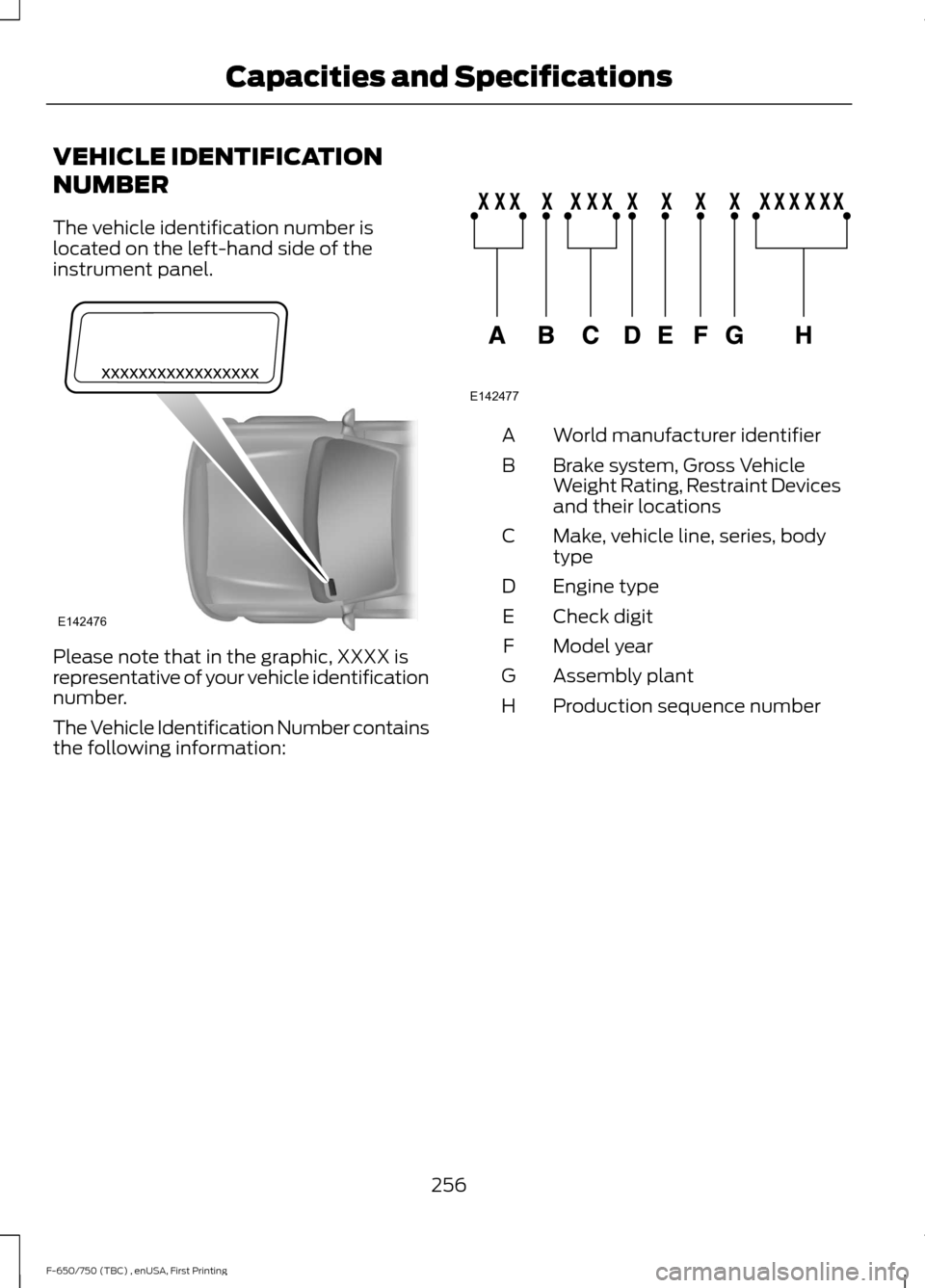
The vehicle identification number is
located on the left-hand side of the
instrument panel.
Please note that in the graphic, XXXX is
representative of your vehicle identification
number.
The Vehicle Identification Number contains
the following information: World manufacturer identifier
A
Brake system, Gross Vehicle
Weight Rating, Restraint Devices
and their locations
B
Make, vehicle line, series, body
type
C
Engine type
D
Check digit
E
Model year
F
Assembly plant
G
Production sequence number
H
256
F-650/750 (TBC) , enUSA, First Printing Capacities and SpecificationsE142476 E142477
Page 318 of 382
•
Brake pads and linings.
• Shock absorbers.
• Struts.
• Engine Belts.
• Engine coolant hoses, clamps and
o-rings.
• Diesel exhaust fluid replenishment.
Interest Free Finance Options
Just a 10% down payment will provide you
with an affordable, no interest, no fee
payment program allowing you all the
security and benefits Ford ESP has to offer
while paying over time. You are
pre-approved with no credit check or
hassles. To learn more, call our Ford
Protect Extended Service Plan specialists
at 800-367-3377.
Ford Protect Extended Service Plan
P.O. Box 321067
Detroit, MI 48232
EXTENDED SERVICE PLAN
(CANADA ONLY)
You can get more protection for your
vehicle by purchasing a Ford Extended
Service Plan. Ford Extended Service Plan
is the only service contract backed by Ford
Motor Company of Canada, Limited.
Depending on the plan you purchase, Ford
Extended Service Plan provides benefits
such as:
• Rental reimbursement.
• Coverage for certain maintenance and
wear items.
• Protection against repair costs after
your New Vehicle Limited Warranty
Coverage expires.
• Roadside Assistance benefits. There are several Ford Extended Service
Plans available in various time, distance
and deductible combinations. Each plan
is tailored to fit your own driving needs,
including reimbursement for towing and
rental. When you purchase Ford Extended
Service Plan, you receive added
peace-of-mind protection throughout
Canada, the United States and Mexico,
provided by a network of participating
authorized Ford Motor Company dealers.
Note:
Repairs performed outside of
Canada, the United States and Mexico are
not eligible for Ford Extended Service Plan
coverage.
This information is subject to change. For
more information, visit your local Ford of
Canada dealer or www.ford.ca to find the
Ford Extended Service Plan that is right for
you.
315
F-650/750 (TBC) , enUSA, First Printing Ford Protect
Page 323 of 382
There are three types of maintenance
intervals for general vehicle environments:
On-Highway, City and Severe Service. In
all applications, monitoring miles
(kilometers) and time and when the engine
is due for an oil change determine the
actual interval. When the engine oil change
is required before the truck lubrication
interval, perform the lubrication at the
same time in order to reduce your vehicle
’s
time out of service.
Air Brake Adjustment WARNING
Failure to maintain proper air brake
adjustment can result in reduction
or loss of braking ability.
A qualified service technician, keeping to
the instructions in the service manual,
should perform air brake inspection and
adjustment or repairs.
Cam Brakes - Automatic Slack
Adjusters
WARNING
Do not manually adjust the
automatic slack adjusters to correct
excessive push rod stroke as it may
result in reduced brake effectiveness and
a vehicle crash. Excessive push rod stroke
indicates that a problem exists with the
automatic adjuster, with the installation
of the adjuster, or with foundation brake
components that manual adjustment does
not remedy. Seek service from a qualified
facility for excessive push rod stroke. Inspect standard air brakes equipped with
automatic slack adjusters for proper brake
adjustment as listed in the maintenance
schedule charts.
However, inspect the brakes more
frequently when subjecting them to heavy
use or adverse operating conditions such
as:
•
Frequent brake applications while fully
loaded.
• Operation on hilly or mountainous
terrain.
• Frequent operation on dirt, gravel or
mud.
Some aftermarket brake linings also
require more frequent inspections.
Owner Checks and Services
Make sure you perform the following basic
maintenance checks and inspections every
month or at six-month intervals.
320
F-650/750 (TBC) , enUSA, First Printing Scheduled Maintenance