sensor FORD F650 2017 13.G Owners Manual
[x] Cancel search | Manufacturer: FORD, Model Year: 2017, Model line: F650, Model: FORD F650 2017 13.GPages: 382, PDF Size: 5.18 MB
Page 85 of 382
Note:
Depending on your vehicle, the power
point cover may open to the right or upward.
When the indicator light on the power point
is:
• On: The power point is working, the
ignition is on and a device is plugged
in.
• Off: The power point is off, the ignition
is off or no device is plugged in.
• Flashing: The power point is in fault
mode.
The power outlet temporarily turns off
power when in fault mode if the device
exceeds the 150 watt limit. Unplug your
device and switch the ignition off. Switch
the ignition back on, but do not plug your
device back in. Let the system cool off and
switch the ignition off to reset the fault
mode. Switch the ignition back on and
make sure the indicator light remains on.
Do not use the power point for certain
electric devices, including:
• Cathode-ray, tube-type televisions.
• Motor loads, such as vacuum cleaners,
electric saws and other electric power
tools or compressor-driven
refrigerators.
• Measuring devices, which process
precise data, such as medical
equipment or measuring equipment.
• Other appliances requiring an
extremely stable power supply such as
microcomputer-controlled electric
blankets or touch-sensor lamps.
82
F-650/750 (TBC) , enUSA, First Printing Auxiliary Power Points
Page 89 of 382
•
Open the windows at least 1 in (3 cm).
• Set your climate control to outside air.
STARTING A DIESEL ENGINE WARNING
Operation of a diesel engine near
flammable vapors in the air may
cause the engine speed to increase
uncontrollably and over speed. If this
situation occurs, mechanical damage, fire,
explosion, personal injury or death could
result. Turning off the ignition key does not
slow or stop the engine due to
uncontrollable fueling of the engine
through flammable vapors being drawn
into the engine air inlet. Operation of
components, for example starter,
alternator, electric motors and static
electricity could also ignite flammable
vapors. Do not operate your vehicle in the
possible presence of flammable vapors
unless both a complete hazard analysis is
carried out and necessary additional safety
processes and/or equipment, for example
vapor testing, air intake shutoff devices
and ventilation are utilized. You are
responsible for using those processes
and/or equipment to make sure that the
diesel engine and all other components on
your vehicle can be operated safely under
the specific conditions and hazards that
may be encountered. Read all starting instructions carefully
before you start your vehicle.
Diesel Engine Fast Start Glow Plug
System
The diesel engine glow system consists of:
•
Eight glow plugs (one per cylinder)
• Glow Plug Control Module
• Engine Coolant Temperature sensor •
Barometric pressure sensor
• Environmental temperature sensor
The powertrain and glow plug control
modules electronically control the glow
plug system. After you switch the ignition
on the glow plug control module
immediately energizes the glow plugs. The
glow plug control module using the engine
coolant temperature, barometric pressure
sensor and environmental temperature
sensor will determine how long the glow
plugs stay energized. The required time for
the glow plugs to be energized decreases
as the coolant temperature, barometric
pressure and environmental temperature
increase.
Before starting the engine, check the
following:
• Make sure all occupants have fastened
their safety belts.
• Make sure the headlamps and
electrical accessories are off.
• Make sure the parking brake is on.
• Make sure the transmission is in park
(P) or neutral (N).
• Turn the ignition key to the on position.
Note: Do not press the accelerator during
starting.
Cold Weather Starting WARNINGS
Do not use starting fluid, for example
ether, in the air intake system (see
air filter decal). Such fluid could
cause immediate explosive damage to the
engine and possible personal injury. Do not add gasoline, gasohol, alcohol
or Kerosene to diesel fuel. This
practice creates a serious fire hazard
and causes engine performance problems. 86
F-650/750 (TBC) , enUSA, First Printing Starting and Stopping the Engine
Page 102 of 382
•
Avoid spilling diesel exhaust fluid on
painted surfaces, carpeting or plastic
components. Immediately wipe away
any diesel exhaust fluid that has spilled
with a damp cloth and water. If it has
already crystallized, use warm water
and a sponge.
• Store diesel exhaust fluid out of direct
sunlight and in temperatures between
23°F (-5°C) and 68°F (20°C).
• Diesel exhaust fluid freezes below 12°F
(-11°C)
.
• Do not store the diesel exhaust fluid
bottle in your vehicle. If it leaks it could
cause damage to interior components
or release an ammonia odor inside your
vehicle.
• Diesel exhaust fluid is non-flammable,
non-toxic, colorless and water-soluble
liquid.
• The system has a diesel exhaust fluid
quality sensor. Dilution of diesel
exhaust fluid or use of any other liquid
in the SCR system leads to a diesel
exhaust fluid system fault, eventually
leading to the vehicle only operating in
idle-only mode.
• Do not dilute diesel exhaust fluid with
water or any other liquid.
• An ammonia odor may be smelled
when the cap is removed or during
refill. Refill diesel exhaust fluid in a well
ventilated area. Typical Diesel Exhaust Fluid Usage
When Using the Power Take Off (PTO) Continuous PTO use—Minimal PTO use
0–7,800 mi (0– 12,550 km)
Contaminated Diesel Exhaust
Fluid or Inoperative Selective
Catalytic Reduction System
Selective catalytic reduction systems are
sensitive to contamination of the diesel
exhaust fluid. Maintaining the purity of the
fluid is important to avoid system
malfunctions. If you remove or drain the
diesel exhaust fluid tank, do not use the
same fluid to refill the tank. The system
has a sensor to monitor fluid quality. A warning lamp illuminates and
a message appears in the
information display if the system
becomes contaminated or inoperative.
Continued driving without replacing diesel
exhaust fluid or having the selective
catalytic reduction system repaired results
in the following actions as required by the
California Air Resources Board (CARB) and
U.S. Environmental Protection Agency
(EPA):
• Within a preset distance to empty,
speed is limited upon vehicle restart.
Prior to this occurring a message
appears in the information display.
• Further vehicle operation without
replacing contaminated diesel exhaust
fluid causes the engine to enter an
idle-only condition. This only occurs
upon vehicle refueling, vehicle idling in
park for 1 hour, or engine shutdown for
10 minutes or more and is indicated by
a message in the information display
indicating required actions to resume
normal operation.
99
F-650/750 (TBC) , enUSA, First Printing Fuel and RefuelingE163176
Page 113 of 382
In the United States, federal law and
certain state laws prohibit removing or
rendering the emission control system
inoperative. Similar federal or provincial
laws may apply in Canada. We do not
recommend any vehicle modification
without determining applicable law.
Tampering with emissions
control system, including related
sensors or the diesel exhaust
fluid injection system can result in reduced
engine power and the service engine soon
warning lamp illuminating in the
information display.
Tampering with a Noise Control
System
Federal law prohibits the following acts or
the causing thereof:
• The removal or rendering inoperative
by any person other than for purposes
of maintenance, repair or replacement
of any device or element of design
incorporated into any new vehicle for
the purpose of noise control prior to its
sale or delivery to the ultimate
purchaser or while it is in use.
• The use of the vehicle after such device
or element of design has been removed
or rendered inoperative by any person.
Among those acts, which the United States
Environmental Protection Agency may
presume to constitute tampering are the
acts listed below:
• Removal of hood blanket, fender apron
absorbers, fender apron barriers,
underbody noise shields or acoustically
absorptive material.
• Tampering or rendering inoperative the
engine speed governor, to allow engine
speed to exceed manufacturer ’s
specifications. The complexity of the diesel engine makes
it so the owner is discouraged from
attempting to perform maintenance other
than the services described in this Owner's
Manual.
If you experience difficulty starting the
engine, rough idling, excessive exhaust
smoke, a decrease in engine performance
or excess fuel consumption, perform the
following checks:
•
A plugged or disconnected air inlet
system or engine air filter element.
• Water in the fuel filter and water
separator.
• A clogged fuel filter.
• Contaminated fuel.
• Air in the fuel system, due to loose
connections.
• An open or pinched sensor hose.
• Check engine oil level.
• Wrong fuel or oil viscosity for the
climatic conditions.
If these checks do not help you correct the
engine performance problem you are
experiencing, have your vehicle checked
as soon as possible.
Noise Emissions Warranty, Prohibited
Tampering Acts and Maintenance
On January 1, 1978, Federal regulation
became effective governing the noise
emission on vehicles weighing over
10,000 lb (4,536 kg) Gross Vehicle Weight
Rating. The preceding statements
concerning prohibited tampering acts and
maintenance, and the noise warranty
found in the Warranty Guide, are
applicable to complete chassis cabs over
10,000 lb (4,536 kg) Gross Vehicle Weight
Rating.
110
F-650/750 (TBC) , enUSA, First Printing Fuel and Refueling
Page 212 of 382
CHANGING THE ENGINE AIR
FILTER - 6.8L
WARNING
To reduce the risk of vehicle damage
and personal burn injuries, do not
start your engine with the air cleaner
removed and do not remove it while the
engine is running. Note:
Operating your vehicle in heavy
snowfall or extreme rain conditions may
allow excessive amounts of snow or water
into the air intake system. This could plug
or soak the air filter that could cause the
engine to lose power or shut down.
When replacing the air filter element, use
a Motorcraft® air filter element. See
Motorcraft Parts (page 254).
Note: Failure to use the correct air filter
element may result in severe engine
damage. Resulting component damage
may not be covered by the vehicle Warranty.
Change the air filter element at the correct
interval. See
Scheduled Maintenance
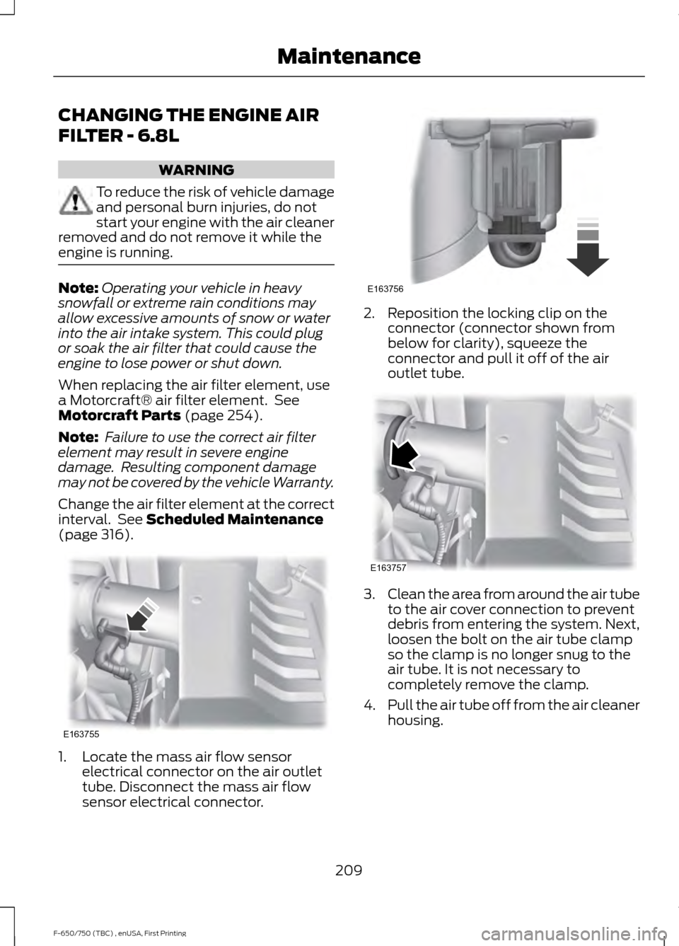
(page 316). 1. Locate the mass air flow sensor
electrical connector on the air outlet
tube. Disconnect the mass air flow
sensor electrical connector. 2. Reposition the locking clip on the
connector (connector shown from
below for clarity), squeeze the
connector and pull it off of the air
outlet tube. 3.
Clean the area from around the air tube
to the air cover connection to prevent
debris from entering the system. Next,
loosen the bolt on the air tube clamp
so the clamp is no longer snug to the
air tube. It is not necessary to
completely remove the clamp.
4. Pull the air tube off from the air cleaner
housing.
209
F-650/750 (TBC) , enUSA, First Printing MaintenanceE163755 E163756 E163757
Page 213 of 382
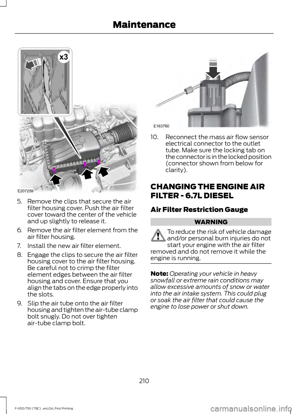
5. Remove the clips that secure the air
filter housing cover. Push the air filter
cover toward the center of the vehicle
and up slightly to release it.
6. Remove the air filter element from the
air filter housing.
7. Install the new air filter element.
8. Engage the clips to secure the air filter housing cover to the air filter housing.
Be careful not to crimp the filter
element edges between the air filter
housing and cover. Ensure that you
align the tabs on the edge properly into
the slots.
9. Slip the air tube onto the air filter housing and tighten the air-tube clamp
bolt snugly. Do not over tighten
air-tube clamp bolt. 10. Reconnect the mass air flow sensor
electrical connector to the outlet
tube. Make sure the locking tab on
the connector is in the locked position
(connector shown from below for
clarity).
CHANGING THE ENGINE AIR
FILTER - 6.7L DIESEL
Air Filter Restriction Gauge WARNING
To reduce the risk of vehicle damage
and/or personal burn injuries do not
start your engine with the air filter
removed and do not remove it while the
engine is running. Note:
Operating your vehicle in heavy
snowfall or extreme rain conditions may
allow excessive amounts of snow or water
into the air intake system. This could plug
or soak the air filter that could cause the
engine to lose power or shut down.
210
F-650/750 (TBC) , enUSA, First Printing MaintenanceE207259
x3 E163760
Page 215 of 382
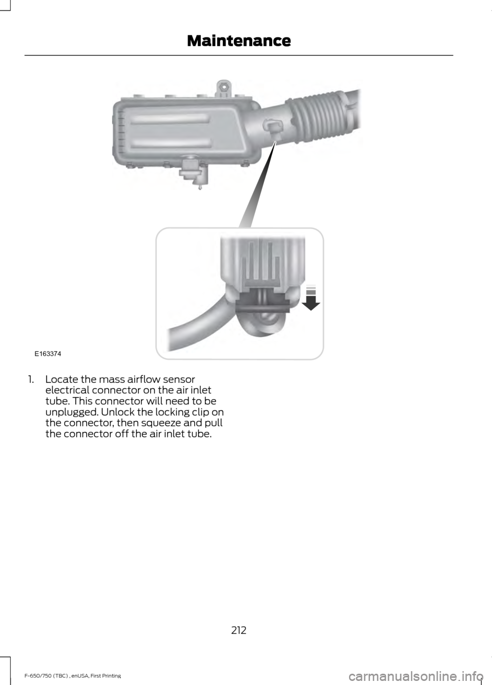
1. Locate the mass airflow sensor
electrical connector on the air inlet
tube. This connector will need to be
unplugged. Unlock the locking clip on
the connector, then squeeze and pull
the connector off the air inlet tube.
212
F-650/750 (TBC) , enUSA, First Printing MaintenanceE163374
Page 216 of 382
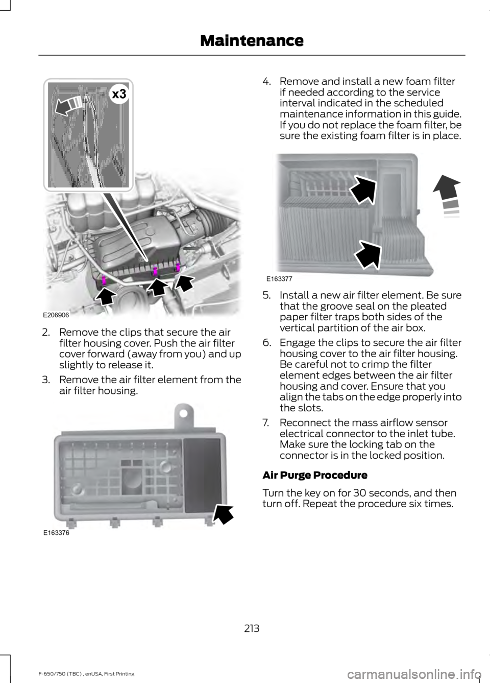
2. Remove the clips that secure the air
filter housing cover. Push the air filter
cover forward (away from you) and up
slightly to release it.
3. Remove the air filter element from the
air filter housing. 4. Remove and install a new foam filter
if needed according to the service
interval indicated in the scheduled
maintenance information in this guide.
If you do not replace the foam filter, be
sure the existing foam filter is in place. 5. Install a new air filter element. Be sure
that the groove seal on the pleated
paper filter traps both sides of the
vertical partition of the air box.
6. Engage the clips to secure the air filter housing cover to the air filter housing.
Be careful not to crimp the filter
element edges between the air filter
housing and cover. Ensure that you
align the tabs on the edge properly into
the slots.
7. Reconnect the mass airflow sensor electrical connector to the inlet tube.
Make sure the locking tab on the
connector is in the locked position.
Air Purge Procedure
Turn the key on for 30 seconds, and then
turn off. Repeat the procedure six times.
213
F-650/750 (TBC) , enUSA, First Printing MaintenanceE206906
x3 E163376 E163377
Page 322 of 382
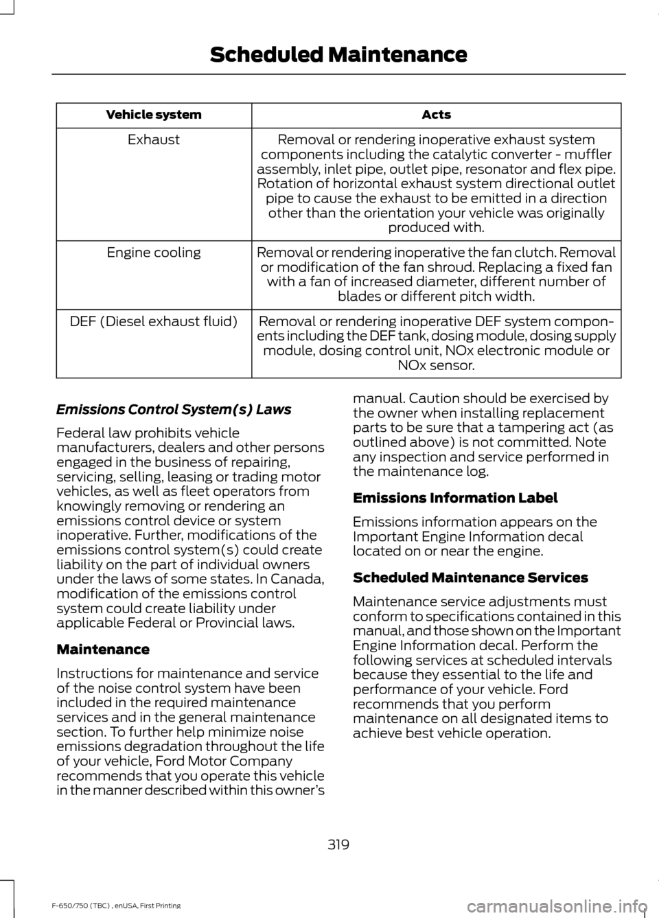
Acts
Vehicle system
Removal or rendering inoperative exhaust system
components including the catalytic converter - muffler
assembly, inlet pipe, outlet pipe, resonator and flex pipe. Rotation of horizontal exhaust system directional outlet pipe to cause the exhaust to be emitted in a directionother than the orientation your vehicle was originally produced with.
Exhaust
Removal or rendering inoperative the fan clutch. Removalor modification of the fan shroud. Replacing a fixed fan with a fan of increased diameter, different number of blades or different pitch width.
Engine cooling
Removal or rendering inoperative DEF system compon-
ents including the DEF tank, dosing module, dosing supply module, dosing control unit, NOx electronic module or NOx sensor.
DEF (Diesel exhaust fluid)
Emissions Control System(s) Laws
Federal law prohibits vehicle
manufacturers, dealers and other persons
engaged in the business of repairing,
servicing, selling, leasing or trading motor
vehicles, as well as fleet operators from
knowingly removing or rendering an
emissions control device or system
inoperative. Further, modifications of the
emissions control system(s) could create
liability on the part of individual owners
under the laws of some states. In Canada,
modification of the emissions control
system could create liability under
applicable Federal or Provincial laws.
Maintenance
Instructions for maintenance and service
of the noise control system have been
included in the required maintenance
services and in the general maintenance
section. To further help minimize noise
emissions degradation throughout the life
of your vehicle, Ford Motor Company
recommends that you operate this vehicle
in the manner described within this owner ’s manual. Caution should be exercised by
the owner when installing replacement
parts to be sure that a tampering act (as
outlined above) is not committed. Note
any inspection and service performed in
the maintenance log.
Emissions Information Label
Emissions information appears on the
Important Engine Information decal
located on or near the engine.
Scheduled Maintenance Services
Maintenance service adjustments must
conform to specifications contained in this
manual, and those shown on the Important
Engine Information decal. Perform the
following services at scheduled intervals
because they essential to the life and
performance of your vehicle. Ford
recommends that you perform
maintenance on all designated items to
achieve best vehicle operation.
319
F-650/750 (TBC) , enUSA, First Printing Scheduled Maintenance