ECU FORD F650/750 2019 User Guide
[x] Cancel search | Manufacturer: FORD, Model Year: 2019, Model line: F650/750, Model: FORD F650/750 2019Pages: 387, PDF Size: 4.78 MB
Page 43 of 387
GENERAL INFORMATION ON
RADIO FREQUENCIES
This device complies with Part 15 of the
FCC Rules and with Licence exempt RSS
Standards of Industry Canada. Operation
is subject to the following two conditions:
•
This device may not cause harmful
interference, and
• This device must accept any
interference received, including
interference that may cause undesired
operation. WARNING: Changes or
modifications not expressively approved
by the party responsible for compliance
could void the user's authority to operate
the equipment. The term "IC:" before the
radio certification number only signifies
that Industry Canada technical
specifications were met.
The typical operating range for your
transmitter is approximately
33 ft (10 m).
Vehicles with the remote start feature will
have a greater range. One of the following
could cause a decrease in operating range:
• Weather conditions.
• Nearby radio towers.
• Structures around the vehicle.
• Other vehicles parked next to your
vehicle.
Other short distance radio transmissions,
for example amateur radios, medical
equipment, wireless headphones, remote
controls and alarm systems can also use
the radio frequency used by your remote
control. If the frequencies are jammed, you
will not be able to use your remote control.
You can lock and unlock the doors with the
key. Note:
Make sure to lock your vehicle before
leaving it unattended.
Note: If you are in range, the remote control
will operate if you press any button
unintentionally.
Note: The remote control contains sensitive
electrical components. Exposure to moisture
or impact may cause permanent damage.
REMOTE CONTROL
(IF EQUIPPED)
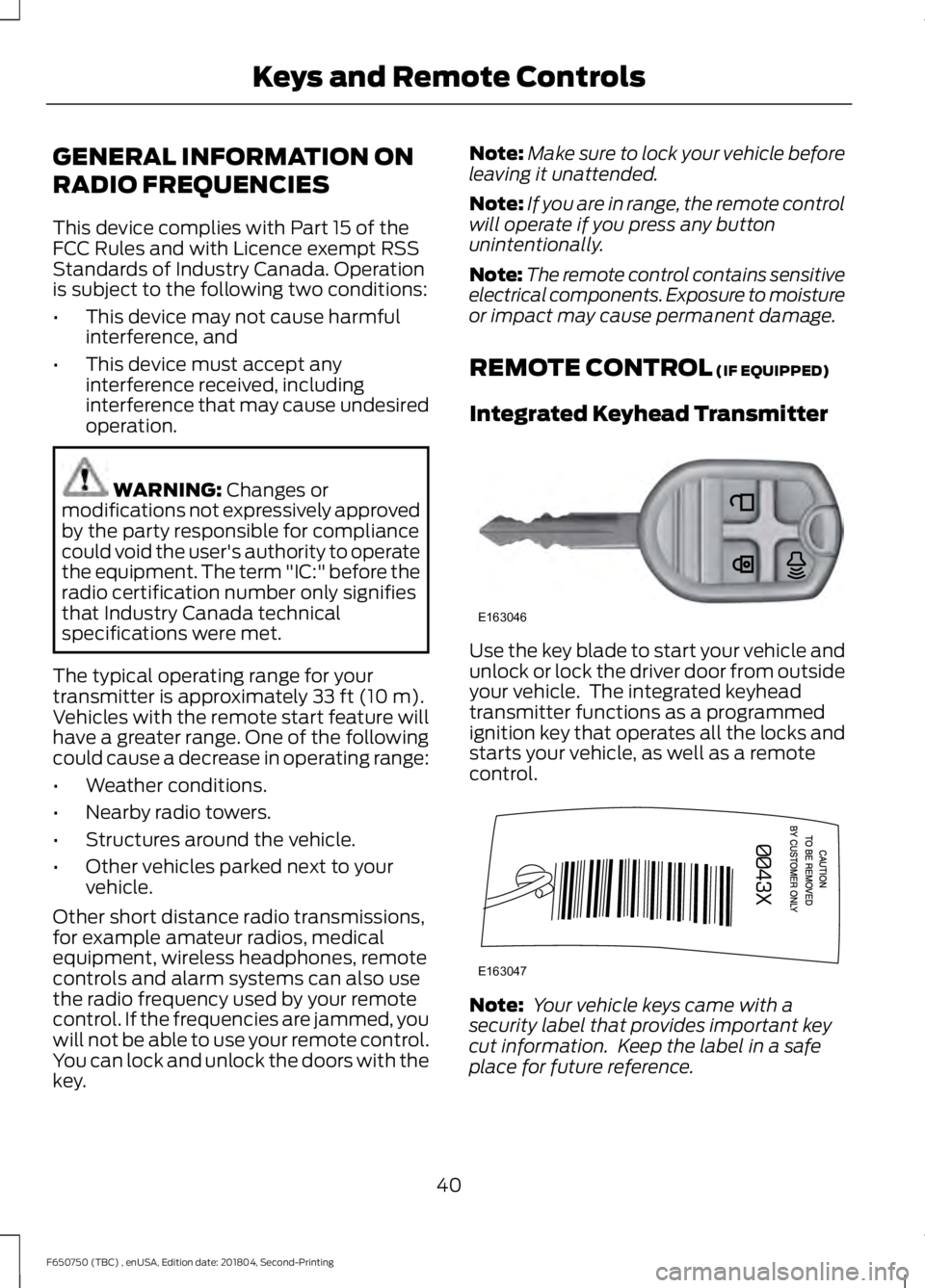
Integrated Keyhead Transmitter Use the key blade to start your vehicle and
unlock or lock the driver door from outside
your vehicle. The integrated keyhead
transmitter functions as a programmed
ignition key that operates all the locks and
starts your vehicle, as well as a remote
control.
Note:
Your vehicle keys came with a
security label that provides important key
cut information. Keep the label in a safe
place for future reference.
40
F650750 (TBC) , enUSA, Edition date: 201804, Second-Printing Keys and Remote ControlsE163046 E163047
Page 47 of 387
PASSIVE ANTI-THEFT
SYSTEM
Note:
The system is not compatible with
non-Ford aftermarket remote start systems.
Use of these systems may result in engine
starting problems and a loss of security
protection.
Note: Metallic objects, electronic devices
or a second coded key on the same key
chain may result in vehicle starting
problems, especially if they are too close to
the key when starting your vehicle. Prevent
these objects from touching the coded key
when starting your vehicle. Switch the
ignition off, move all objects on the key
chain away from the coded key and restart
your vehicle if a problem occurs.
Note: Do not leave a duplicate coded key
in your vehicle. Always take your keys and
lock all doors when leaving your vehicle.
SecuriLock®
The system helps prevent the engine from
starting unless you use a coded key
programmed to your vehicle. Using the
wrong key may prevent your vehicle from
starting. A message may appear in the
information display.
If you are unable to start your vehicle with
a coded key, it is not operating correctly.
A message may appear in the information
display.
Automatic Arming
The system arms when you switch the
ignition off.
Automatic Disarming
The system disarms when you switch the
ignition on with a coded key. Replacement Keys
Note:
Your vehicle may have two integrated
keyhead transmitters.
The integrated keyhead transmitter
functions as a programmed ignition key
that operates all the locks and starts your
vehicle, as well as a remote control.
If your programmed transmitters or
standard SecuriLock coded keys are lost
or stolen and you do not have an extra
coded key, you will need to have your
vehicle towed to an authorized dealer. You
need to erase the key codes from your
vehicle and program new coded keys.
Store an extra programmed key away from
your vehicle in a safe place. Contact an
authorized dealer to purchase additional
spare or replacement keys.
Programming a Spare Key
Note: You can program a maximum of six
keys to your vehicle.
You can program your own integrated
keyhead transmitter or standard
SecuriLock coded keys to your vehicle.
This procedure programs both the vehicle
immobilizer keycode and the remote
control to your vehicle.
Only use integrated keyhead transmitters
or standard SecuriLock keys.
You must have two previously
programmed coded keys and the new
unprogrammed key readily accessible.
Contact an authorized dealer to have the
spare key programmed if two previously
programmed keys are not available.
Read and understand the entire procedure
before you begin.
1. Insert the first previously programmed
coded key into the ignition.
2. Switch the ignition from off to on. Keep
the ignition on for at least 3 seconds,
but no more than 10 seconds.
44
F650750 (TBC) , enUSA, Edition date: 201804, Second-Printing Security
Page 48 of 387
3.
Switch the ignition off and remove the
first coded key from the ignition.
4. After at least 3 seconds but within 10 seconds of switching the ignition off,
insert the second previously coded key
into the ignition.
5. Switch the ignition from off to on. Keep
the ignition on for at least 3 seconds,
but no more than 10 seconds.
6. Switch the ignition off and remove the
second previously programmed coded
key from the ignition.
7. After at least 3 seconds but within 10 seconds of switching the ignition off
and removing the previously
programmed coded key, insert the new
unprogrammed key into the ignition.
8. Switch the ignition from off to on. Keep
the ignition on for at least six seconds.
9. Remove the newly programmed coded
key from the ignition.
The doors lock then unlock to confirm that
programming was successful. If you have
successfully programmed the new
integrated keyhead transmitter, it will start
your vehicle and operate the remote entry
system.
If programming was unsuccessful, wait 20
seconds and repeat Steps 1 through 8. If
you are still unsuccessful, take your vehicle
to an authorized dealer.
45
F650750 (TBC) , enUSA, Edition date: 201804, Second-Printing Security
Page 118 of 387
AUTOMATIC TRANSMISSION
WARNING: Apply the parking
brake, shift into park (P), switch the
ignition off and remove the key before
you leave your vehicle. Failure to follow
this instruction could result in personal
injury or death.
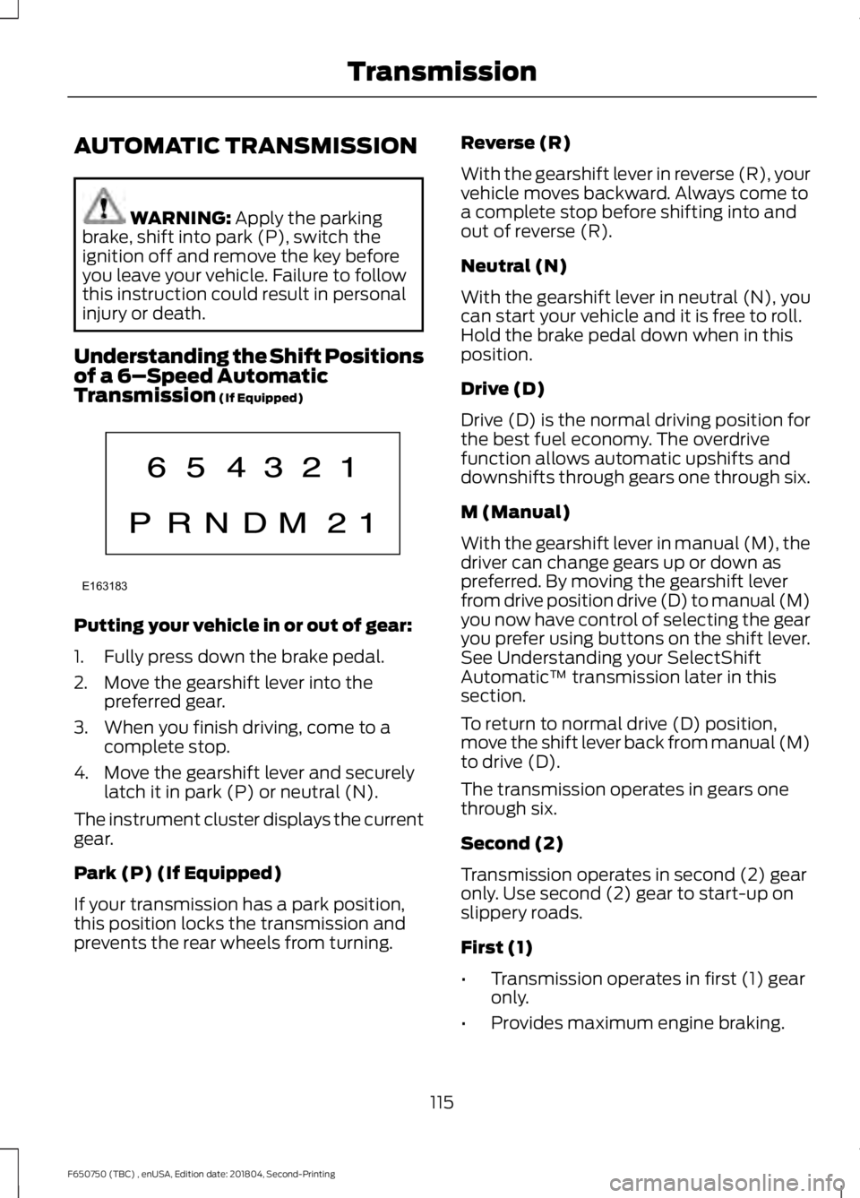
Understanding the Shift Positions
of a 6– Speed Automatic
Transmission
(If Equipped) Putting your vehicle in or out of gear:
1. Fully press down the brake pedal.
2. Move the gearshift lever into the
preferred gear.
3. When you finish driving, come to a complete stop.
4. Move the gearshift lever and securely latch it in park (P) or neutral (N).
The instrument cluster displays the current
gear.
Park (P) (If Equipped)
If your transmission has a park position,
this position locks the transmission and
prevents the rear wheels from turning. Reverse (R)
With the gearshift lever in reverse (R), your
vehicle moves backward. Always come to
a complete stop before shifting into and
out of reverse (R).
Neutral (N)
With the gearshift lever in neutral (N), you
can start your vehicle and it is free to roll.
Hold the brake pedal down when in this
position.
Drive (D)
Drive (D) is the normal driving position for
the best fuel economy. The overdrive
function allows automatic upshifts and
downshifts through gears one through six.
M (Manual)
With the gearshift lever in manual (M), the
driver can change gears up or down as
preferred. By moving the gearshift lever
from drive position drive (D) to manual (M)
you now have control of selecting the gear
you prefer using buttons on the shift lever.
See Understanding your SelectShift
Automatic
™ transmission later in this
section.
To return to normal drive (D) position,
move the shift lever back from manual (M)
to drive (D).
The transmission operates in gears one
through six.
Second (2)
Transmission operates in second (2) gear
only. Use second (2) gear to start-up on
slippery roads.
First (1)
• Transmission operates in first (1) gear
only.
• Provides maximum engine braking.
115
F650750 (TBC) , enUSA, Edition date: 201804, Second-Printing TransmissionE163183
Page 121 of 387
Automatic Transmission Adaptive
Learning
This feature's design is to increase
durability and provide consistent shift feel
over the life of your vehicle. A new vehicle
or transmission could have firm shifts, soft
shifts or both. This operation is normal and
does not affect function or durability of the
transmission. Over time, the adaptive
learning process fully updates transmission
operation. Additionally, whenever you
disconnect the battery or install a new
battery, the system must relearn the
strategy.
Brake-Shift Interlock
WARNING: Do not drive your
vehicle until you verify that the
stoplamps are working. WARNING:
When doing this
procedure, you need to take the
transmission out of park (P) which
means your vehicle can roll freely. To
avoid unwanted vehicle movement,
always fully apply the parking brake prior
to doing this procedure. Use wheels
chocks if appropriate. WARNING:
If the parking brake is
fully released, but the brake warning
lamp remains illuminated, the brakes
may not be working properly. Have your
vehicle checked as soon as possible.
Your vehicle is equipped with a brake-shift
interlock feature that prevents the
gearshift lever from moving from park (P)
when the ignition is in the 3 (on) position
and the brake pedal is not pressed. If you cannot move the gearshift lever out
of park (P) position with the ignition in the
4 (on) position and the brake pedal
pressed, a malfunction could have
occurred. It is possible that a fuse has
blown or your vehicle
’s brake lamps are
not operating properly.
See Fuse
Specification Chart (page 167).
If the fuse is not blown and the brake
lamps are working properly, the following
procedure allows you to move the gearshift
lever from park (P):
1. Apply the parking brake. Switch the ignition key to 1 (off), then remove the
key.
2. Move the steering column to the full down and full rearward position
(toward the driver ’s seat).
3. Remove the gearshift lever boot.
4. Place fingers into hole where you removed the gearshift lever boot and
pull top half of shroud up and forward
to separate it from the lower half of the
shroud. There is a hinge at the forward
edge of the top shroud. Roll the top
half of the shroud upward on the hinge
point to clear the hazard flasher button,
then pull straight rearward toward the
driver ’s seat to remove.
5. Remove the top half of the shroud.
6. Remove the three fasteners under the column that secure the lower shroud
half to the column.
118
F650750 (TBC) , enUSA, Edition date: 201804, Second-Printing Transmission
Page 129 of 387
5. Tighten the nut until the spring is fully
caged and brakes released. Do not
loosen or remove the release stud and
nut unless you completely assemble
and securely clamp the brake chamber.
6. After restoring the air pressure, unscrew and remove the release stud
and install in the carrying pocket. Install
the access plug.
AIR BRAKES (IF EQUIPPED) WARNING:
Do not drive or
continue to drive if the low air pressure
buzzer is sounding or the brake warning
light is lit. These warnings indicate that
air pressure is not to normal operating
level. Continued use of the vehicle could
result in loss of braking ability. WARNING:
Avoid repeated light
application of the brake pedal. This
depletes air pressure faster and could
result in loss of braking capability. WARNING:
Do not move the
vehicle when the air pressure is
insufficient because the brake system
may be inoperative.
After starting the engine, give the air
compressor time to build up the air
pressure to
60 psi (414 kPa) before moving
your vehicle. Periodically check the air pressure gauge
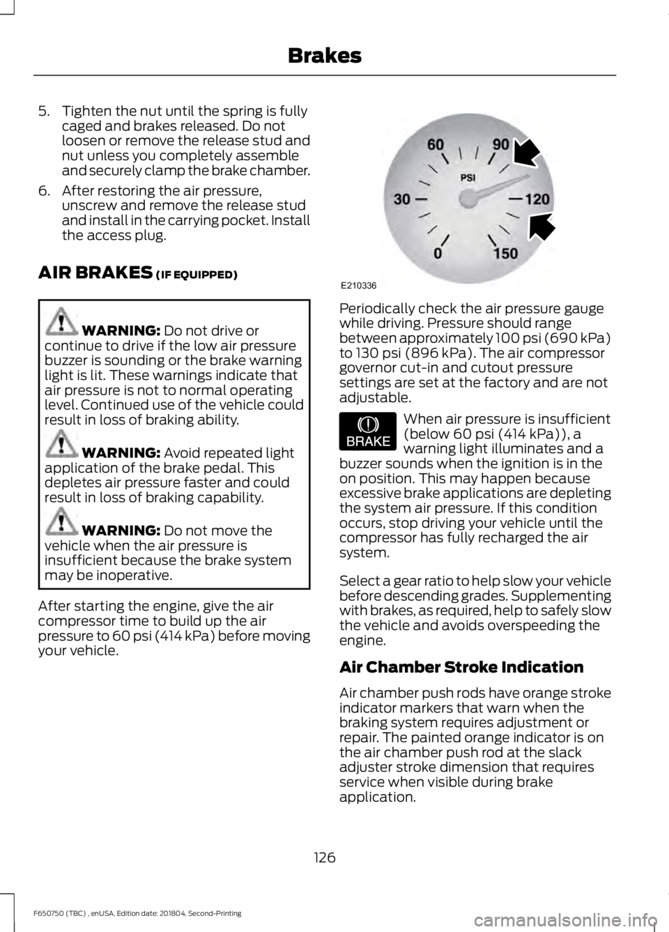
while driving. Pressure should range
between approximately 100 psi (690 kPa)
to
130 psi (896 kPa). The air compressor
governor cut-in and cutout pressure
settings are set at the factory and are not
adjustable. When air pressure is insufficient
(below
60 psi (414 kPa)), a
warning light illuminates and a
buzzer sounds when the ignition is in the
on position. This may happen because
excessive brake applications are depleting
the system air pressure. If this condition
occurs, stop driving your vehicle until the
compressor has fully recharged the air
system.
Select a gear ratio to help slow your vehicle
before descending grades. Supplementing
with brakes, as required, help to safely slow
the vehicle and avoids overspeeding the
engine.
Air Chamber Stroke Indication
Air chamber push rods have orange stroke
indicator markers that warn when the
braking system requires adjustment or
repair. The painted orange indicator is on
the air chamber push rod at the slack
adjuster stroke dimension that requires
service when visible during brake
application.
126
F650750 (TBC) , enUSA, Edition date: 201804, Second-Printing BrakesE210336 E206772
Page 139 of 387
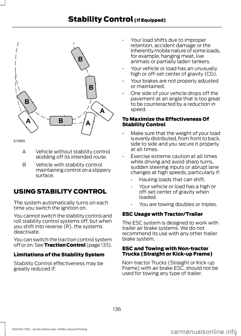
Vehicle without stability control
skidding off its intended route.
A
Vehicle with stability control
maintaining control on a slippery
surface.
B
USING STABILITY CONTROL
The system automatically turns on each
time you switch the ignition on.
You cannot switch the stability control and
roll stability control systems off, but when
you shift into reverse (R), the systems
deactivate.
You can switch the traction control system
off or on. See Traction Control (page 133).
Limitations of the Stability System
Stability Control effectiveness may be
greatly reduced if: •
Your load shifts due to improper
retention, accident damage or the
inherently mobile nature of some loads,
for example, hanging meat, live
animals or partially laden tankers.
• Your vehicle or load has an unusually
high or off-set center of gravity (CG).
• Your brakes are not properly adjusted
or maintained.
• One side of your vehicle drops off the
pavement at an angle that is too great
to be counteracted by a reduction in
speed.
To Maximize the Effectiveness Of
Stability Control
• Make sure that the weight of your load
is evenly distributed, from front to back,
side to side and you secure it properly
at all times.
• Exercise extreme caution at all times
while driving and avoid sharp turns,
sudden steering inputs or abrupt lane
changes at high speeds, particularly if:
•Hauling loads that can shift.
• Your vehicle or load has a high or
off-set center of gravity when
loaded.
• You are towing doubles or triples.
ESC Usage with Tractor/Trailer
The ESC system is designed to work with
trailer air brake systems. We do not
recommend its use with any other trailer
brake system.
ESC and Towing with Non-tractor
Trucks (Straight or Kick-up Frame)
Non-tractor Trucks (Straight or Kick-up
Frame) with air brake ESC, should not be
used for towing any type of trailer.
136
F650750 (TBC) , enUSA, Edition date: 201804, Second-Printing Stability Control (If Equipped)E72903A
AA
B
BB
B
Page 150 of 387
•
Shift to a lower gear when driving down
a long or steep hill. Do not apply the
brakes continuously, as they may
overheat and become less effective.
• If your transmission is equipped with
the Tow/Haul feature, use this feature
when towing. This provides engine
braking and helps eliminate excessive
transmission shifting for optimum fuel
economy and transmission cooling.
• Allow more distance for stopping with
a trailer attached. Anticipate stops and
brake gradually.
FIFTH WHEEL OPERATION WARNING: Failure to follow the
fifth wheel manufacturer ’s instructions
for hooking and unhooking as well as
sliding the fifth wheel could result in an
accident, personal injury or death. WARNING:
When the tractor and
trailer are parked unattended, the trailer
brake hand control should never be used
to apply the brake, since air may leak
from the system, allowing vehicle
movement, resulting in possible property
damage, personal injury or death.
Before hook-up, make sure:
• The fifth wheel jaws are fully open.
• The fifth wheel is fully tilted back to
prevent body damage when the tractor
is backed under a trailer.
• You block the trailer wheels and adjust
and apply the trailer spring brakes.
Never chase a trailer.
• The brake hoses and light cords are
clear of the fifth wheel. Hook-up
1. Back the tractor squarely under the
trailer, engaging the fifth-wheel jaws
on the kingpin. Always back up slowly;
make sure the trailer is neither too high
nor too low. Avoid backing under the
trailer from an angle.
2. Connect the service and emergency brake hoses and trailer light connector.
3. Inspect the jaws of the fifth wheel to be sure they have fully closed on the
trailer kingpin and the trailer plate is
resting securely on the fifth wheel.
4. Make sure the coupler release lever is in the locked position.
5. Charge the trailer brake system. Set the trailer brakes, with either the hand
valve or tractor protection valve. Pull
against the trailer for an extra check of
proper hook-up. Do not pull hard
enough to damage or strain the
equipment.
6. Set the tractor parking brakes and fully
raise the trailer landing gear.
7. Check the operation of all trailer lights
and correct any lights that may be
faulty.
Un-hook
1. Try to keep the tractor and trailer in a straight line.
2. Apply the parking brakes.
3. Lower the trailer landing gear, making sure it is on solid, level ground. The
weight of the trailer is to be on the
landing gear.
4. Block the trailer wheels.
5. Disconnect the brake hoses and light cords. Be sure hoses and cords are
clear.
6. Pull coupler release lever to disengage
the fifth wheel jaws.
147
F650750 (TBC) , enUSA, Edition date: 201804, Second-Printing Towing
Page 165 of 387
In the case of 1 or 2 above, the consumer
must also notify the manufacturer of the
need for the repair of the nonconformity
at the following address:
Ford Motor Company
16800 Executive Plaza Drive
Mail Drop 3NE-B
Dearborn, MI 48126
You are required to submit your warranty
dispute to BBB AUTO LINE before asserting
in court any rights or remedies conferred
by California Civil Code Section 1793.22(b).
You are also required to use BBB AUTO
LINE before exercising rights or seeking
remedies created by the Federal
Magnuson-Moss Warranty Act, 15 U.S.C.
sec. 2301 et seq. If you choose to seek
redress by pursuing rights and remedies
not created by California Civil Code Section
1793.22(b) or the Magnuson-Moss
Warranty Act, resort to BBB AUTO LINE is
not required by those statutes.
THE BETTER BUSINESS
BUREAU (BBB) AUTO LINE
PROGRAM (U.S. ONLY)
Your satisfaction is important to Ford
Motor Company and to your dealer. If a
warranty concern has not been resolved
using the three-step procedure outlined
earlier in this chapter in the Getting the
Services you need section, you may be
eligible to participate in the BBB AUTO
LINE program.
The BBB AUTO LINE program consists of
two parts – mediation and arbitration.
During mediation, a representative of the
BBB will contact both you and Ford Motor
Company to explore options for settlement
of the claim. If an agreement is not reached
during mediation or you do not want to
participate in mediation, and if your claim
is eligible, you may participate in the
arbitration process. An arbitration hearing
will be scheduled so that you can present
your case in an informal setting before an
impartial person. The arbitrator will
consider the testimony provided and make
a decision after the hearing.
Disputes submitted to the BBB AUTO LINE
program are usually decided within forty
days after you file your claim with the BBB.
You are not bound by the decision, and
may reject the decision and proceed to
court where all findings of the BBB Auto
Line dispute, and decision, are admissible
in the court action. Should you choose to
accept the BBB AUTO LINE decision, Ford
is then bound by the decision, and must
comply with the decision within 30 days
of receipt of your acceptance letter.
BBB AUTO LINE Application: Using the
information provided below, please call or
write to request a program application.
You will be asked for your name and
address, general information about your
new vehicle, information about your
warranty concerns, and any steps you have
already taken to try to resolve them. A
Customer Claim Form will be mailed that
will need to be completed, signed and
returned to the BBB along with proof of
ownership. Upon receipt, the BBB will
review the claim for eligibility under the
Program Summary Guidelines.
You can get more information by
calling BBB AUTO LINE at
1-800-955-5100, or writing to:
BBB AUTO LINE
3033 Wilson Boulevard, Suite 600
Arlington, Virginia 22201
BBB AUTO LINE applications can also be
requested by calling the Ford Motor
Company Customer Relationship Center
at 1-800-392-3673.
162
F650750 (TBC) , enUSA, Edition date: 201804, Second-Printing Customer Assistance
Page 168 of 387
Obtaining a French Owner
’s
Manual
French Owner ’s Manual can be obtained
from your authorized dealer or by
contacting Helm, Incorporated using the
contact information listed previously in this
section.
REPORTING SAFETY DEFECTS
(U.S. ONLY)
If you believe that your vehicle has
a defect which could cause a
crash or could cause injury or
death, you should immediately
inform the National Highway
Traffic Safety Administration
(NHTSA) in addition to notifying
Ford Motor Company.
If NHTSA receives similar
complaints, it may open an
investigation, and if it finds that a
safety defect exists in a group of
vehicles, it may order a recall and
remedy campaign. However,
NHTSA cannot become involved
in individual problems between
you, your dealer, or Ford Motor
Company. To contact NHTSA, you may call
the Vehicle Safety Hotline
toll-free at 1-888-327-4236 (TTY:
1-800-424-9153); go to
http://www.safercar.gov; or write
to:
Administrator
1200 New Jersey Avenue,
Southeast
Washington, D.C. 20590
You can also obtain other
information about motor vehicle
safety from
http://www.safercar.gov.
REPORTING SAFETY DEFECTS
(CANADA ONLY)
If you believe that your vehicle has a defect
which could cause a crash or could cause
injury or death, you should immediately
inform Transport Canada and Ford of
Canada.
Transport Canada Contact Information
http://www.tc.gc.ca/eng/motorvehiclesafety/reporting-defects-motor-
vehicles.html (English)
Website
http://www.tc.gc.ca/fra/securiteautomobile/signaler-defauts-vehicules-
automobiles.html (French)
Website
1–800–333–0510
Phone
165
F650750 (TBC) , enUSA, Edition date: 201804, Second-Printing Customer Assistance