ECU FORD F650/750 2019 Owner's Manual
[x] Cancel search | Manufacturer: FORD, Model Year: 2019, Model line: F650/750, Model: FORD F650/750 2019Pages: 387, PDF Size: 4.78 MB
Page 185 of 387
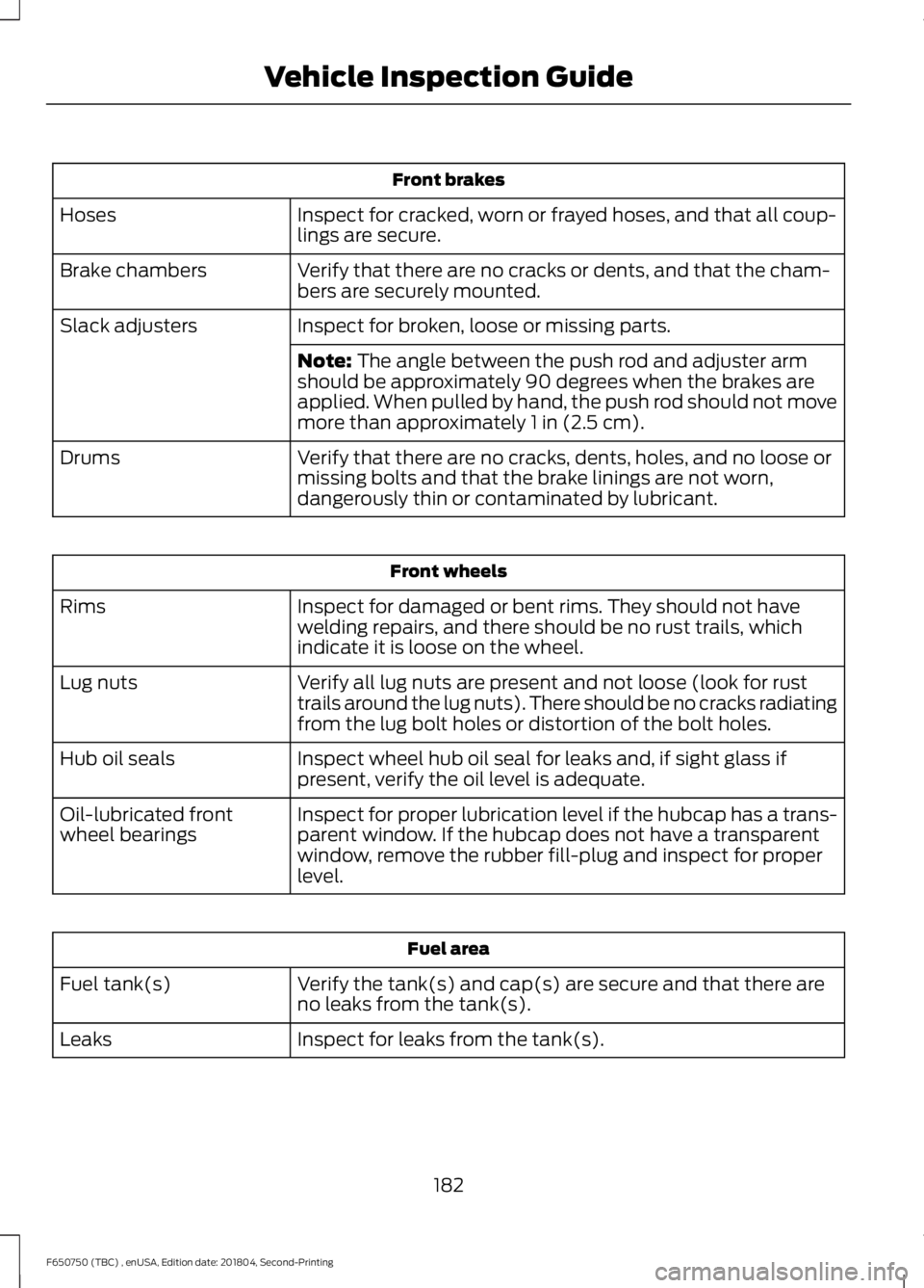
Front brakes
Inspect for cracked, worn or frayed hoses, and that all coup-
lings are secure.
Hoses
Verify that there are no cracks or dents, and that the cham-
bers are securely mounted.
Brake chambers
Inspect for broken, loose or missing parts.
Slack adjusters
Note: The angle between the push rod and adjuster arm
should be approximately 90 degrees when the brakes are
applied. When pulled by hand, the push rod should not move
more than approximately
1 in (2.5 cm).
Verify that there are no cracks, dents, holes, and no loose or
missing bolts and that the brake linings are not worn,
dangerously thin or contaminated by lubricant.
Drums Front wheels
Inspect for damaged or bent rims. They should not have
welding repairs, and there should be no rust trails, which
indicate it is loose on the wheel.
Rims
Verify all lug nuts are present and not loose (look for rust
trails around the lug nuts). There should be no cracks radiating
from the lug bolt holes or distortion of the bolt holes.
Lug nuts
Inspect wheel hub oil seal for leaks and, if sight glass if
present, verify the oil level is adequate.
Hub oil seals
Inspect for proper lubrication level if the hubcap has a trans-
parent window. If the hubcap does not have a transparent
window, remove the rubber fill-plug and inspect for proper
level.
Oil-lubricated front
wheel bearings Fuel area
Verify the tank(s) and cap(s) are secure and that there are
no leaks from the tank(s).
Fuel tank(s)
Inspect for leaks from the tank(s).
Leaks
182
F650750 (TBC) , enUSA, Edition date: 201804, Second-Printing Vehicle Inspection Guide
Page 186 of 387
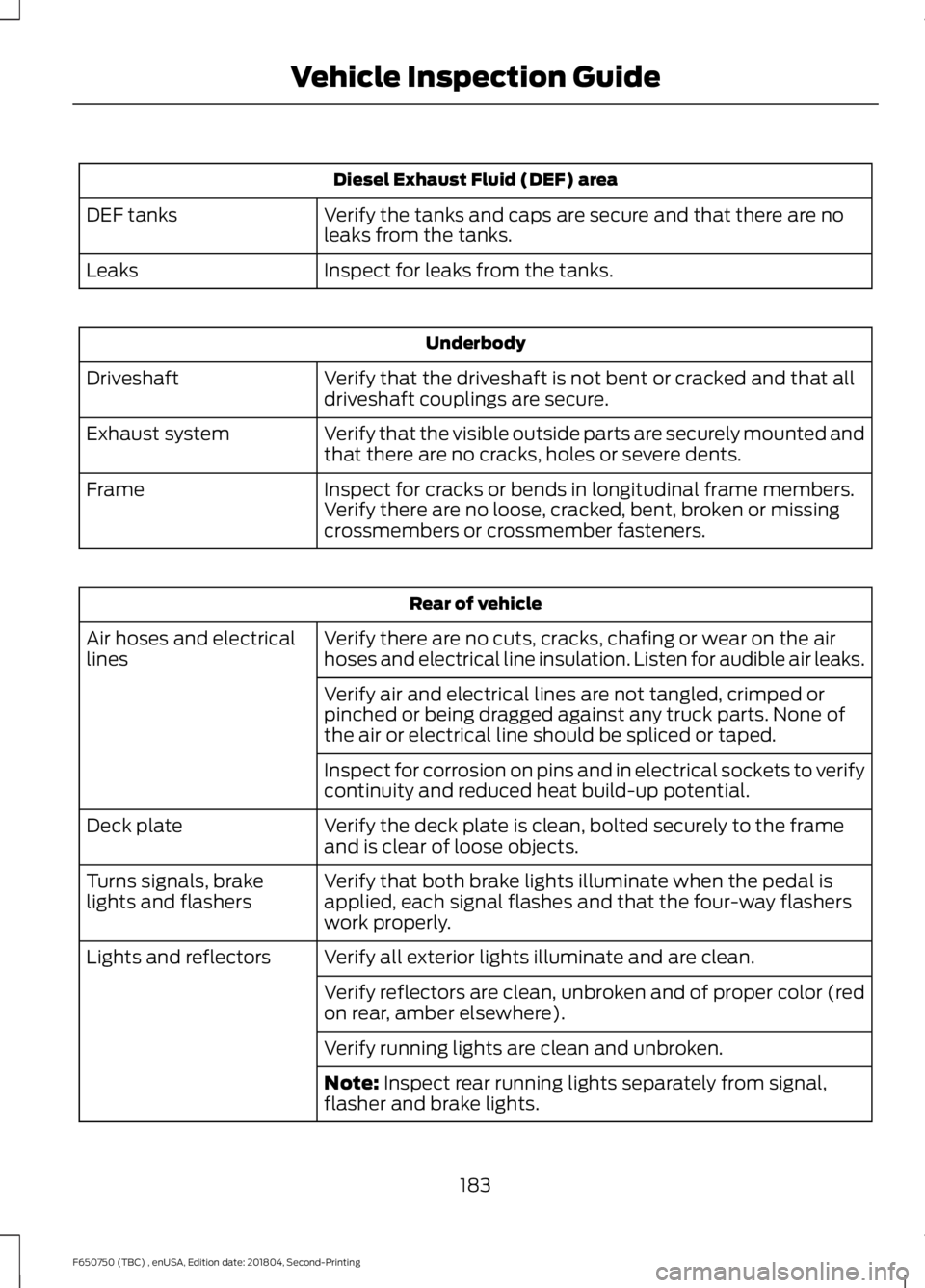
Diesel Exhaust Fluid (DEF) area
Verify the tanks and caps are secure and that there are no
leaks from the tanks.
DEF tanks
Inspect for leaks from the tanks.
Leaks Underbody
Verify that the driveshaft is not bent or cracked and that all
driveshaft couplings are secure.
Driveshaft
Verify that the visible outside parts are securely mounted and
that there are no cracks, holes or severe dents.
Exhaust system
Inspect for cracks or bends in longitudinal frame members.
Verify there are no loose, cracked, bent, broken or missing
crossmembers or crossmember fasteners.
Frame Rear of vehicle
Verify there are no cuts, cracks, chafing or wear on the air
hoses and electrical line insulation. Listen for audible air leaks.
Air hoses and electrical
lines
Verify air and electrical lines are not tangled, crimped or
pinched or being dragged against any truck parts. None of
the air or electrical line should be spliced or taped.
Inspect for corrosion on pins and in electrical sockets to verify
continuity and reduced heat build-up potential.
Verify the deck plate is clean, bolted securely to the frame
and is clear of loose objects.
Deck plate
Verify that both brake lights illuminate when the pedal is
applied, each signal flashes and that the four-way flashers
work properly.
Turns signals, brake
lights and flashers
Verify all exterior lights illuminate and are clean.
Lights and reflectors
Verify reflectors are clean, unbroken and of proper color (red
on rear, amber elsewhere).
Verify running lights are clean and unbroken.
Note: Inspect rear running lights separately from signal,
flasher and brake lights.
183
F650750 (TBC) , enUSA, Edition date: 201804, Second-Printing Vehicle Inspection Guide
Page 188 of 387
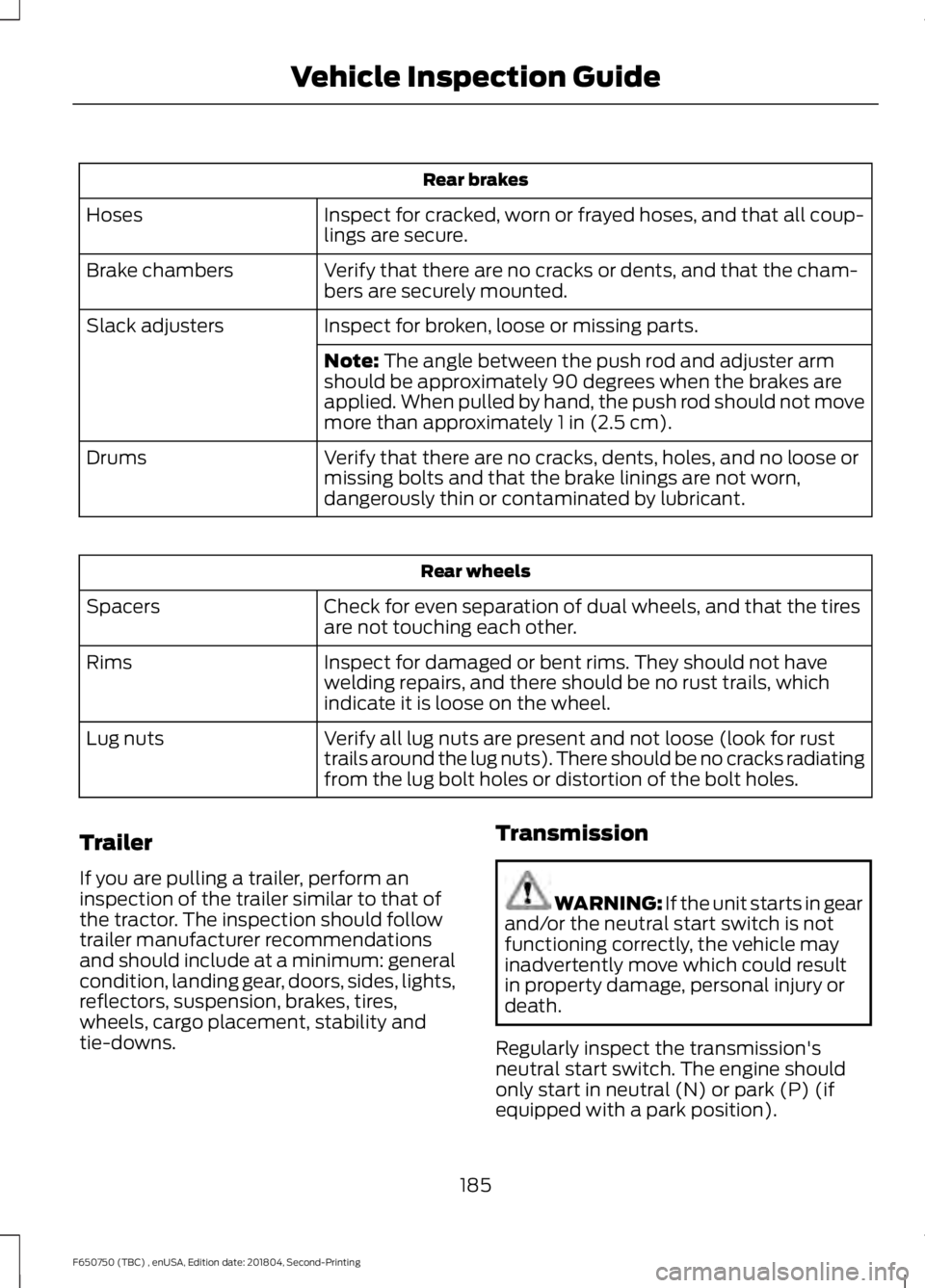
Rear brakes
Inspect for cracked, worn or frayed hoses, and that all coup-
lings are secure.
Hoses
Verify that there are no cracks or dents, and that the cham-
bers are securely mounted.
Brake chambers
Inspect for broken, loose or missing parts.
Slack adjusters
Note: The angle between the push rod and adjuster arm
should be approximately 90 degrees when the brakes are
applied. When pulled by hand, the push rod should not move
more than approximately
1 in (2.5 cm).
Verify that there are no cracks, dents, holes, and no loose or
missing bolts and that the brake linings are not worn,
dangerously thin or contaminated by lubricant.
Drums Rear wheels
Check for even separation of dual wheels, and that the tires
are not touching each other.
Spacers
Inspect for damaged or bent rims. They should not have
welding repairs, and there should be no rust trails, which
indicate it is loose on the wheel.
Rims
Verify all lug nuts are present and not loose (look for rust
trails around the lug nuts). There should be no cracks radiating
from the lug bolt holes or distortion of the bolt holes.
Lug nuts
Trailer
If you are pulling a trailer, perform an
inspection of the trailer similar to that of
the tractor. The inspection should follow
trailer manufacturer recommendations
and should include at a minimum: general
condition, landing gear, doors, sides, lights,
reflectors, suspension, brakes, tires,
wheels, cargo placement, stability and
tie-downs. Transmission WARNING: If the unit starts in gear
and/or the neutral start switch is not
functioning correctly, the vehicle may
inadvertently move which could result
in property damage, personal injury or
death.
Regularly inspect the transmission's
neutral start switch. The engine should
only start in neutral (N) or park (P) (if
equipped with a park position).
185
F650750 (TBC) , enUSA, Edition date: 201804, Second-Printing Vehicle Inspection Guide
Page 219 of 387
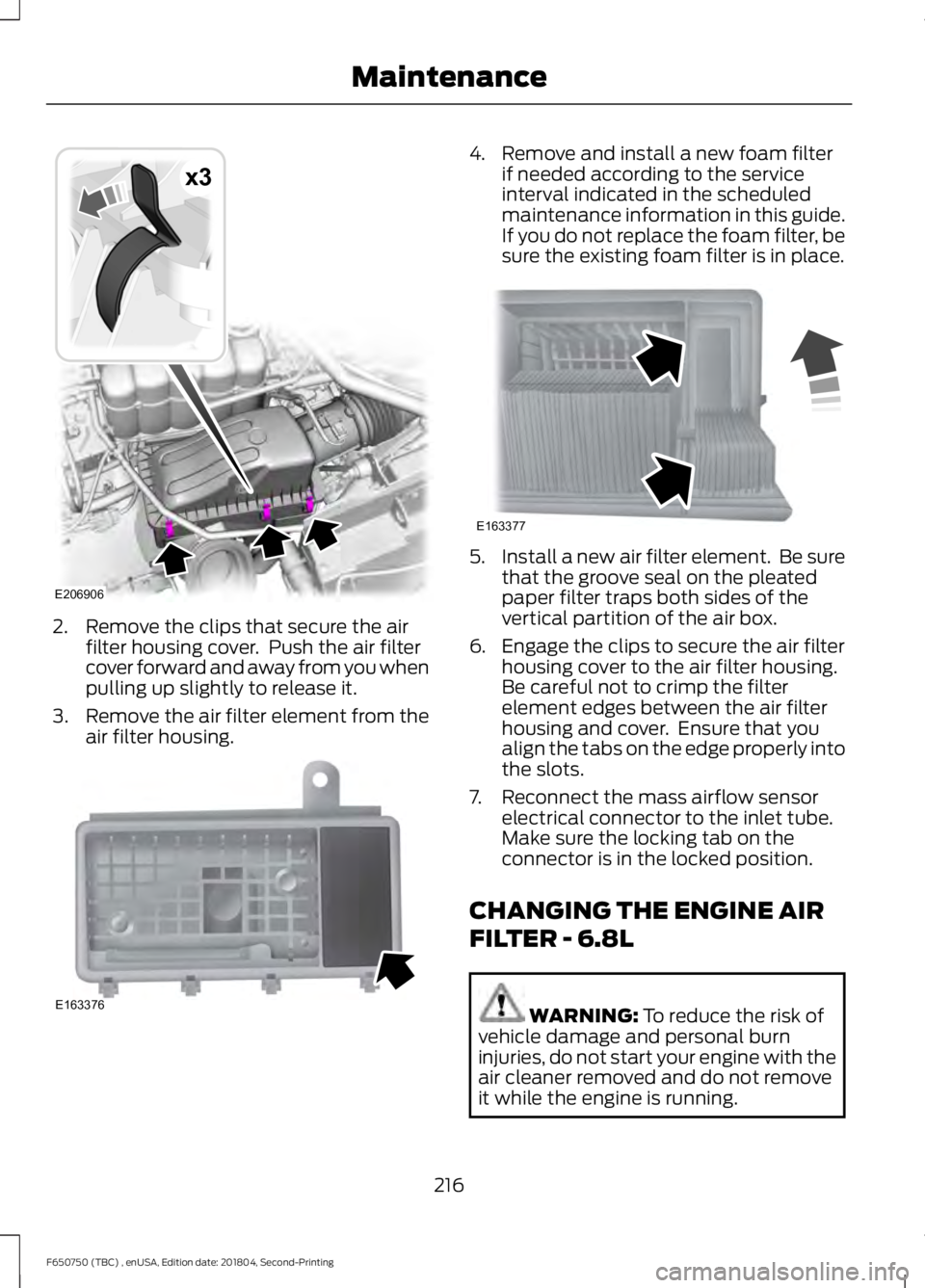
2. Remove the clips that secure the air
filter housing cover. Push the air filter
cover forward and away from you when
pulling up slightly to release it.
3. Remove the air filter element from the
air filter housing. 4. Remove and install a new foam filter
if needed according to the service
interval indicated in the scheduled
maintenance information in this guide.
If you do not replace the foam filter, be
sure the existing foam filter is in place. 5.
Install a new air filter element. Be sure
that the groove seal on the pleated
paper filter traps both sides of the
vertical partition of the air box.
6. Engage the clips to secure the air filter housing cover to the air filter housing.
Be careful not to crimp the filter
element edges between the air filter
housing and cover. Ensure that you
align the tabs on the edge properly into
the slots.
7. Reconnect the mass airflow sensor electrical connector to the inlet tube.
Make sure the locking tab on the
connector is in the locked position.
CHANGING THE ENGINE AIR
FILTER - 6.8L WARNING: To reduce the risk of
vehicle damage and personal burn
injuries, do not start your engine with the
air cleaner removed and do not remove
it while the engine is running.
216
F650750 (TBC) , enUSA, Edition date: 201804, Second-Printing MaintenanceE206906
x3 E163376 E163377
Page 221 of 387
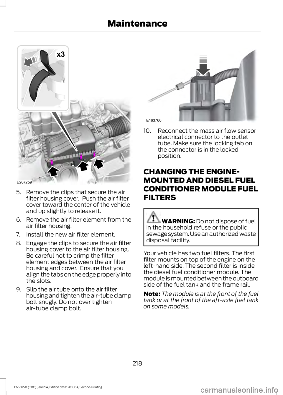
5. Remove the clips that secure the air
filter housing cover. Push the air filter
cover toward the center of the vehicle
and up slightly to release it.
6. Remove the air filter element from the
air filter housing.
7. Install the new air filter element.
8. Engage the clips to secure the air filter housing cover to the air filter housing.
Be careful not to crimp the filter
element edges between the air filter
housing and cover. Ensure that you
align the tabs on the edge properly into
the slots.
9. Slip the air tube onto the air filter housing and tighten the air-tube clamp
bolt snugly. Do not over tighten
air-tube clamp bolt. 10. Reconnect the mass air flow sensor
electrical connector to the outlet
tube. Make sure the locking tab on
the connector is in the locked
position.
CHANGING THE ENGINE-
MOUNTED AND DIESEL FUEL
CONDITIONER MODULE FUEL
FILTERS WARNING: Do not dispose of fuel
in the household refuse or the public
sewage system. Use an authorized waste
disposal facility.
Your vehicle has two fuel filters. The first
filter mounts on top of the engine on the
left-hand side. The second filter is inside
the diesel fuel conditioner module. The
module is mounted between the outboard
side of the fuel tank and the frame rail.
Note: The module is at the front of the fuel
tank or at the front of the aft-axle fuel tank
on some models.
218
F650750 (TBC) , enUSA, Edition date: 201804, Second-Printing MaintenanceE207259
x3 E163760
Page 230 of 387
SUSPENSION SYSTEM
INSPECTION
Note:
Do not adjust air suspension height
to any setting other than the specified
setting. Altering the height setting changes
the driveline angle and may result in
unwarrantable component damage, such
as transmission component damage.
Verify drive axle air suspension height and
height control valve performance at engine
oil change intervals.
Periodically check:
• Condition of spring leaves for evidence
of fatigue, bending or breakage.
• Condition of suspension mounting
brackets and bushings.
• Torque rod mounting fasteners for
tightness.
• For proper suspension alignment.
Maintain proper alignment at all times.
• U-bolts. After the chassis has been
operating under load for 1,000 mi
(1,600 km) or six months (whichever
comes first), the U-bolt nuts must be
re-torqued. Re-torque the U-bolt nuts
every
37,000 mi (60,000 km)
thereafter. Clean and lubricate the
U-bolt and nut threads and seats to
make sure a like new condition when
re-torqueing. See
Spring U-Bolt
Check (page 228).
FRAME AND TOW HOOK
INSPECTION
Your vehicle's chassis is manufactured
with frame rails of either HSLA steel or
heat-treated steel. Handle each in a
specific manner to make sure maximum
service life. Consult the service manual or
an authorized dealer before attempting
frame repair or modification. It is important, particularly on vehicles that
use tow hooks frequently, to inspect the
front and rear tow hooks for damage or a
loose mounting.
REAR AXLE FLUID CHECK
Your rear axle may have an optional
synthetic lubricant that allows the use of
extended service intervals. A tag on the
filler plug identifies the use of the synthetic
lubricant.
Only use a lubricant that meets
manufacturer specifications. Only use a
lubricant that meets manufacturer
specifications. Use of a non-approved rear
axle lubricant may cause internal axle
component damage. See Capacities and
Specifications
(page 261).
Checking the Fluid Level
1. Park your vehicle on level ground.
2. Set the parking brake and shift into position neutral (N) or park (P). Turn
the engine off.
3. Clean any dirt from around the axle filler plug.
4. Remove the filler plug and inspect the lubricant level. It should be at the
bottom of the filler plug opening.
5. Add lubricant, if necessary, through the
filler plug opening.
6. Clean and install the filler plug securely.
Changing the Fluid
Note: Drain the rear axle while the lubricant
is warm.
1. Park your vehicle on level ground.
2. Set the parking brake and shift into position neutral (N) or park (P). Turn
the engine off.
3. Clean any dirt from around the axle filler and drain plugs.
227
F650750 (TBC) , enUSA, Edition date: 201804, Second-Printing Maintenance
Page 231 of 387
4.
Remove the filler and drain plugs. Drain
the lubricant into a suitable container.
Dispose of all used automotive fluids
in a responsible manner following your
local authorized standards.
5. Clean and install the drain plug securely.
6. Add lubricant through the filler plug opening.
7. Clean and install the filler plug securely.
SPRING U-BOLT CHECK
Check and tighten the U-bolt nuts after
your vehicle has been operated under load
for 1,000 mi (1,600 km) or six months,
whichever occurs first.
Check and tighten the U-bolt nuts every
37,000 mi (60,000 km)
.
Check and tighten the U-bolt nuts with
your vehicle at curb height and unloaded.
Inspect the U-bolt threads for rust and
debris. Clean the threads if contaminated.
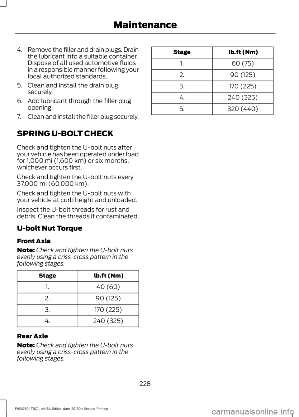
U-bolt Nut Torque
Front Axle
Note: Check and tighten the U-bolt nuts
evenly using a criss-cross pattern in the
following stages. lb.ft (Nm)
Stage
40 (60)
1.
90 (125)
2.
170 (225)
3.
240 (325)
4.
Rear Axle
Note: Check and tighten the U-bolt nuts
evenly using a criss-cross pattern in the
following stages. lb.ft (Nm)
Stage
60 (75)
1.
90 (125)
2.
170 (225)
3.
240 (325)
4.
320 (440)
5.
228
F650750 (TBC) , enUSA, Edition date: 201804, Second-Printing Maintenance
Page 254 of 387
USING SNOW CHAINS
WARNING: Snow tires must be
the same size, load index, and speed
rating as those originally provided by
Ford. Use of any tire or wheel not
recommended by Ford can affect the
safety and performance of your vehicle,
which could result in an increased risk of
loss of vehicle control, vehicle rollover,
personal injury, and death. Additionally,
the use of non-recommended tires and
wheels could cause steering, suspension,
axle, transfer case, or power transfer unit
failure. It is also strongly advised to
follow the Ford recommended tire
inflation pressure found on the Safety
Compliance Certification Label (affixed
to either the door hinge pillar, door-latch
post, or the door edge that meets the
door-latch post, next to the driver ’s
seating position), or Tire Label which is
located on the B-Pillar or the edge of the
driver door. Failure to follow the tire
pressure recommendations can cause
uneven treadwear patterns and
adversely affect the way your vehicle
handles.
The tires on your vehicle have all-weather
treads to provide traction in rain and snow.
However, in some climates, you may need
to use snow tires and cables. If you need
to use cables, it is recommended that steel
wheels (of the same size and
specifications) be used, as cables may chip
aluminum wheels.
Note: The suspension insulation and
bumpers help prevent vehicle damage. Do
not remove these components from your
vehicle when using snow tires and chains.
Follow these guidelines when using snow
tires and chains: •
If possible, avoid fully loading your
vehicle.
• Use only SAE Class S chains.
• Install chains securely, verifying that
the chains do not touch any wiring,
brake lines or fuel lines.
• Drive cautiously. If you hear the chains
rub or bang against your vehicle, stop
and retighten the chains. If this does
not work, remove the chains to prevent
damage to your vehicle.
• Remove the tire chains when they are
no longer needed. Do not use tire
chains on dry roads.
If you have any questions regarding snow
chains or cables, please contact your
authorized dealer.
CHANGING A ROAD WHEEL
If you get a flat tire while driving, do not
apply the brake heavily. Instead, gradually
decrease your speed. Hold the steering
wheel firmly and slowly move to a safe
place on the side of the road.
Tire Change Procedure WARNING:
When one of the front
wheels is off the ground, the
transmission alone will not prevent the
vehicle from moving or slipping off the
jack, even if the transmission is in park
(P). WARNING:
To help prevent the
vehicle from moving when you change
a tire, be sure to place the transmission
in park (P), set the parking brake and
block (in both directions) the wheel that
is diagonally opposite (other side and
end of the vehicle) to the tire being
changed.
251
F650750 (TBC) , enUSA, Edition date: 201804, Second-Printing Wheels and Tires
Page 256 of 387
TECHNICAL SPECIFICATIONS
Wheel Lug Nut Torque Specifications
WARNING: When you install a wheel, always remove any corrosion, dirt or foreign
materials present on the mounting surfaces of the wheel or the surface of the wheel
hub, brake drum or brake disc that contacts the wheel. Make sure to secure any fasteners
that attach the rotor to the hub so they do not interfere with the mounting surfaces of
the wheel. Installing wheels without correct metal-to-metal contact at the wheel
mounting surfaces can cause the wheel nuts to loosen and the wheel to come off while
your vehicle is in motion, resulting in loss of vehicle control, personal injury or death. lb.ft (Nm)
1
Bolt size
450–500 lb.ft (610–678 Nm)
M22 x 1.5
1 Torque specifications are for nut and bolt threads free of dirt and rust. Use only Ford
recommended replacement fasteners.
On vehicles equipped with single rear wheels, retighten the lug nuts to the specified torque
at 100 miles (160 kilometers) after any wheel disturbance (such as tire rotation, changing
a flat tire, wheel removal).
On vehicles equipped with dual rear wheels, retighten the lug nuts to the specified torque
at 100 miles (160 kilometers) and again at 500 miles (800 kilometers) of new vehicle
operation and after any wheel disturbance (such as tire rotation, changing a flat tire,
wheel removal).
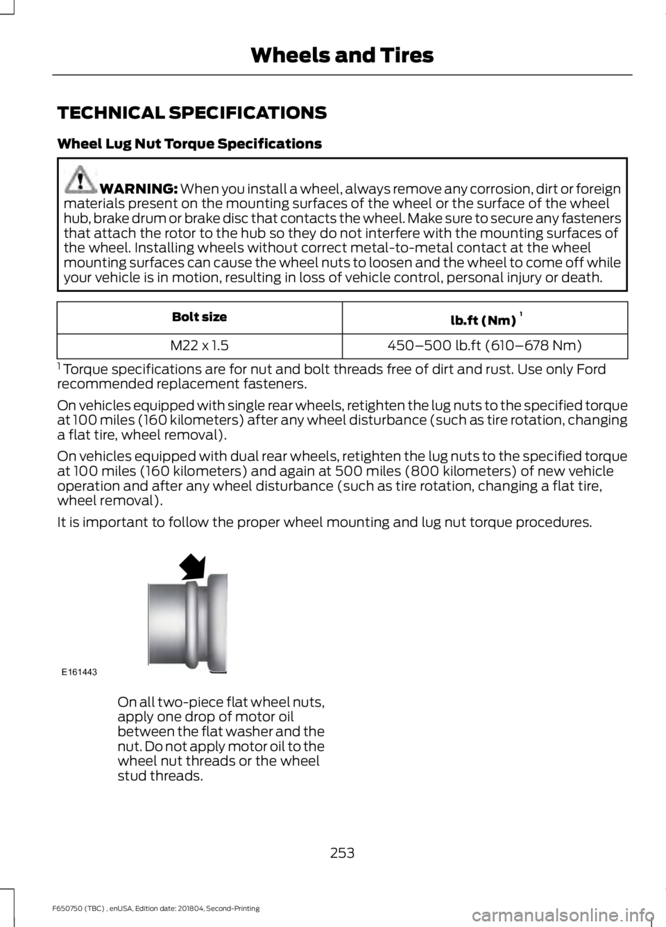
It is important to follow the proper wheel mounting and lug nut torque procedures. On all two-piece flat wheel nuts,
apply one drop of motor oil
between the flat washer and the
nut. Do not apply motor oil to the
wheel nut threads or the wheel
stud threads.
253
F650750 (TBC) , enUSA, Edition date: 201804, Second-Printing Wheels and TiresE161443
Page 287 of 387
Action
Condition
Message
The signal is blocked. When
you move into an open area,
the signal should return.
The signal is lost from the
SiriusXM satellite or Siri-
usXM tower to your vehicle
antenna.
No Signal
No action required. The
process may take up to
three minutes.
Update of channel
programming in progress.
Updating\b
Contact SiriusXM at 1-888-
539-7474 to resolve
subscription issues.
Your satellite service is no
longer available.
Questions? Call
1-888-539-7474
Use the channel guide to
turn off the Lock or Skip
function on that station.
All the channels in the
selected category are either
skipped or locked.
None found
Check Channel Guide
No action required.
SiriusXM has updated the
channels available for your
vehicle.
Subscription Updated
AUDIO INPUT JACK (IF EQUIPPED) WARNING:
Driving while
distracted can result in loss of vehicle
control, crash and injury. We strongly
recommend that you use extreme
caution when using any device that may
take your focus off the road. Your
primary responsibility is the safe
operation of your vehicle. We
recommend against the use of any
hand-held device while driving and
encourage the use of voice-operated
systems when possible. Make sure you
are aware of all applicable local laws
that may affect the use of electronic
devices while driving. WARNING:
Always place your
device in a secure location in your vehicle
so it does not become a projectile in a
sudden stop or crash. Failure to follow
this instruction could result in personal
injury. 284
F650750 (TBC) , enUSA, Edition date: 201804, Second-Printing Audio SystemE191758