door lock FORD F650/750 2021 User Guide
[x] Cancel search | Manufacturer: FORD, Model Year: 2021, Model line: F650/750, Model: FORD F650/750 2021Pages: 390, PDF Size: 5.16 MB
Page 68 of 390
Engine Oil Pressure Gauge
Indicates engine oil pressure. At normal
operating temperature, the level indicator
is in the normal range. If the pressure gauge
falls below the normal range, stop your
vehicle, switch off the engine and check
the engine oil level. Add oil if needed. If the
oil level is correct, have your vehicle
checked by an authorized dealer.
Engine Coolant Temperature
Gauge
WARNING: Do not remove the
coolant reservoir cap when the engine is
on or the cooling system is hot. Wait 10
minutes for the cooling system to cool
down. Cover the coolant reservoir cap
with a thick cloth to prevent the
possibility of scalding and slowly remove
the cap. Failure to follow this instruction
could result in personal injury.
Indicates engine coolant temperature. At
normal operating temperature, the level
indicator is in the normal range. If the
engine coolant temperature exceeds the
normal range, stop your vehicle as soon as
possible, switch off the engine and let the
engine cool.
Fuel Gauge
The fuel gauge indicates about how much
fuel is in the fuel tank.
The arrow adjacent to the fuel pump
symbol indicates on which side of your
vehicle the fuel filler door is located.
Note: The fuel gauge may vary slightly
when your vehicle is moving or on a slope. Low Fuel Reminder
A low fuel level reminder displays and
sounds when the distance to empty
reaches
75 mi (120 km) to empty for
MyKey, and at 50 mi (80 km), 25 mi
(40 km), 10 mi (20 km) and 0 mi (0 km)
for all vehicle keys.
Note: The low fuel reminder can appear at
different fuel gauge positions depending on
fuel economy conditions. This variation is
normal.
Distance to Empty
Indicates the approximate distance your
vehicle can travel on the fuel remaining in
the tank. Changes in driving pattern can
cause the value to not only decrease but
also increase or stay constant for periods
of time.
Configurable Gauge
Transmission Fluid Temperature Gauge
Indicates transmission fluid temperature.
At normal operating temperature, the level
indicator is in the normal range. If the
transmission fluid temperature exceeds
the normal range, stop your vehicle as soon
as possible and verify the airflow is not
restricted by snow or debris blocking
airflow through the grille.
Special operating conditions such as
snowplowing, towing, or off-road use may
cause higher than normal operating
temperatures. See
Special Operating
Conditions Scheduled Maintenance
(page
329).
To lower the transmission temperature
into the normal range, alter the severity of
your driving conditions. Operating the
transmission for extended periods with the
gauge in the higher than normal area may
cause internal transmission damage. If the
gauge continues to show high
temperatures, see an authorized dealer.
65
F650750 (TBC) , enUSA, Edition date: 202010, Second-Printing Instrument Cluster
Page 70 of 390
Door Ajar
Displays when the ignition is on
and any door is not completely
closed.
Electronic Locking Differential (If
Equipped) Illuminates when using the
electronic locking differential.
Engine Coolant Temperature If it illuminates when your vehicle
is moving, this indicates that the
engine is overheating. Stop your
vehicle as soon as it is safe to do so and
switch the engine off. Have your vehicle
checked as soon as possible. See Engine
Coolant Check
(page 226). idk
Engine Oil Pressure If it illuminates with the engine
running, or when you are driving,
this indicates a malfunction.
Stop your vehicle as soon as it is safe to
do so and switch off the engine. Check the
engine oil level.
Note: Do not resume your journey if it
illuminates despite the level being correct.
Have the system checked as soon as
possible.
Exhaust Brake On
(If Equipped) The exhaust brake indicator light
illuminates when you switch the
exhaust brake on.
Fasten Seatbelt Illuminates and a tone sounds
to remind you to fasten your
seatbelt. High Beam Illuminates when you switch on
the high beam headlamps. It
flashes when you use the
headlamp flasher.
Hydromax Illuminates to indicate normal
hydromax booster reserve
system activation when the
engine is off and the service brake pedal is
applied. This light may also illuminate
momentarily if the engine is running and
the driver turns the steering wheel fully in
one direction while braking. If the light
remains on while the engine is running, this
indicates inadequate hydraulic booster
pressure or reserve pump system failure.
Stop the vehicle as soon as possible and
seek service immediately by your
authorized dealer.
Parking Lamps Illuminates when you switch the
parking lamps on.
Low Fuel Level
(If Equipped) Illuminates when the fuel level
is low or the fuel tank is nearly
empty. Refuel as soon as
possible.
Parking Brake Warning Illuminates briefly when you
switch the ignition to the on
position, with the engine off. It
also illuminates when you apply the
parking brake. If the park brake lamp does
not illuminate at these times, seek service
immediately. Vehicles with the power
parking brake option: If the park brake
warning lamp begins to blink after setting
67
F650750 (TBC) , enUSA, Edition date: 202010, Second-Printing Instrument Cluster E163170 E171217 E71880 E146190 E208810
Page 100 of 390
•
Shortly after the engine has shut down,
the electrical system simulates a key
off and even though the ignition is still
on, the electrical system simulates a
normal accessory delay period before
shutting down.
• You must switch the ignition off to
reset the system before restarting your
vehicle.
The engine idle shutdown timer does not
start if:
• The engine is operating in battery
charge protect or power take-off mode.
• The exhaust emission control device is
regenerating.
ENGINE BLOCK HEATER (IF
EQUIPPED) WARNING:
Failure to follow engine
block heater instructions could result in
property damage or serious personal
injury. WARNING: Do not use your heater
with ungrounded electrical systems or
two-pronged adapters. There is a risk of
electrical shock.
Note: The heater is most effective when
outdoor temperatures are below
0°F
(-18°C).
The heater acts as a starting aid by
warming the engine coolant. This allows
the climate control system to respond
quickly. The equipment includes a heater
element (installed in the engine block) and
a wire harness. You can connect the
system to a grounded 120-volt AC
electrical source. We recommend that you do the following
for a safe and correct operation:
•
Use a 16-gauge outdoor extension cord
that is product certified by
Underwriter ’s Laboratory (UL) or
Canadian Standards Association
(CSA). This extension cord must be
suitable for use outdoors, in cold
temperatures, and be clearly marked
Suitable for Use with Outdoor
Appliances. Do not use an indoor
extension cord outdoors. This could
result in an electric shock or become a
fire hazard.
• Use as short an extension cord as
possible.
• Do not use multiple extension cords.
• Make sure that when in operation, the
extension cord plug and heater cord
plug connections are free and clear of
water. This could cause an electric
shock or fire.
• Make sure your vehicle is parked in a
clean area, clear of combustibles.
• Make sure the heater, heater cord and
extension cord are firmly connected.
• Check for heat anywhere in the
electrical hookup once the system has
been operating for approximately 30
minutes.
• Make sure the system is unplugged and
properly stowed before starting and
driving your vehicle. Make sure the
protective cover seals the prongs of the
block heater cord plug when not in use.
• Make sure the heater system is
checked for proper operation before
winter.
Using the Engine Block Heater
Make sure the receptacle terminals are
clean and dry prior to use. Clean them with
a dry cloth if necessary.
97
F650750 (TBC) , enUSA, Edition date: 202010, Second-Printing Starting and Stopping the Engine
Page 160 of 390
The warning system is in two stages. At
first the system issues a temporary warning
that you need to take a rest. This message
only appears for a short time. If the system
detects further reduction in driving
alertness, another warning could be issued
which remains in the information display
for a longer time. Press OK on the steering
wheel control to clear the warning. When
active the system runs in the background
and only issues a warning if required.
Resetting the System
You can reset the system by either:
•
Switching the ignition off and on.
• Stopping the vehicle and then opening
and closing the driver door.
LANE KEEPING SYSTEM (IF
EQUIPPED) WARNING: You are responsible for
controlling your vehicle at all times. The
system is designed to be an aid and does
not relieve you of your responsibility to
drive with due care and attention. Failure
to follow this instruction could result in
the loss of control of your vehicle,
personal injury or death. WARNING:
Always drive with due
care and attention when using and
operating the controls and features on
your vehicle. WARNING:
In cold and severe
weather conditions the system may not
function. Rain, snow and spray can all
limit sensor performance. WARNING:
The system will not
operate if the sensor cannot track the
road lane markings. WARNING:
The sensor may
incorrectly track lane markings as other
structures or objects. This can result in
a false or missed warning. WARNING:
Large contrasts in
outside lighting can limit sensor
performance. WARNING:
The system may not
operate properly if the sensor is blocked.
Keep the windshield free from
obstruction. WARNING:
If damage occurs in the
immediate area surrounding the sensor,
have your vehicle checked as soon as
possible. WARNING:
The system may not
correctly operate if your vehicle is fitted
with a suspension kit not approved by
us.
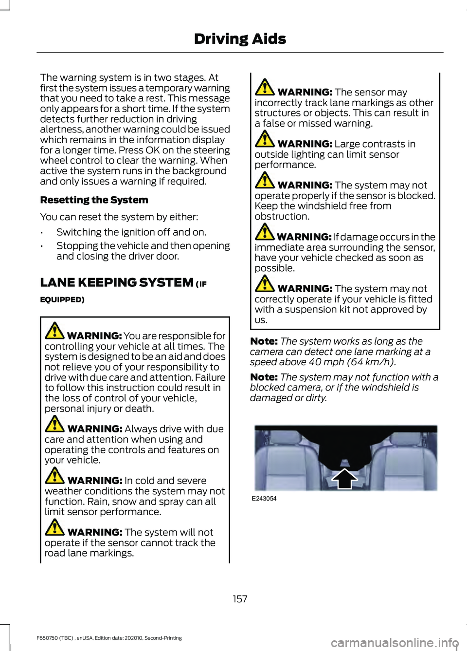
Note: The system works as long as the
camera can detect one lane marking at a
speed above
40 mph (64 km/h).
Note: The system may not function with a
blocked camera, or if the windshield is
damaged or dirty. 157
F650750 (TBC) , enUSA, Edition date: 202010, Second-Printing Driving AidsE243054
Page 171 of 390
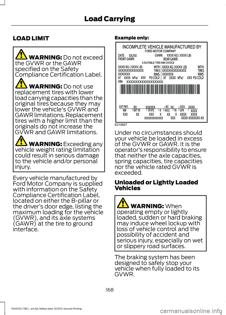
LOAD LIMIT
WARNING: Do not exceed
the GVWR or the GAWR
specified on the Safety
Compliance Certification Label. WARNING:
Do not use
replacement tires with lower
load carrying capacities than the
original tires because they may
lower the vehicle's GVWR and
GAWR limitations. Replacement
tires with a higher limit than the
originals do not increase the
GVWR and GAWR limitations. WARNING: Exceeding any
vehicle weight rating limitation
could result in serious damage
to the vehicle and/or personal
injury.
Every vehicle manufactured by
Ford Motor Company is supplied
with information on the Safety
Compliance Certification Label,
located on either the B-pillar or
the driver ’s door edge, listing the
maximum loading for the vehicle
(GVWR), and its axle systems
(GAWR) at the tire to ground
interface. Example only:
Under no circumstances should
your vehicle be loaded in excess
of the GVWR or GAWR. It is the
operator
’s responsibility to ensure
that neither the axle capacities,
spring capacities, tire capacities
nor the vehicle rated GVWR is
exceeded.
Unloaded or Lightly Loaded
Vehicles WARNING:
When
operating empty or lightly
loaded, sudden or hard braking
may induce wheel lockup with
loss of vehicle control and the
possibility of accident and
serious injury, especially on wet
or slippery road surfaces.
The braking system has been
designed to safely stop your
vehicle when fully loaded to its
GVWR.
168
F650750 (TBC) , enUSA, Edition date: 202010, Second-Printing Load CarryingE210937
Page 202 of 390
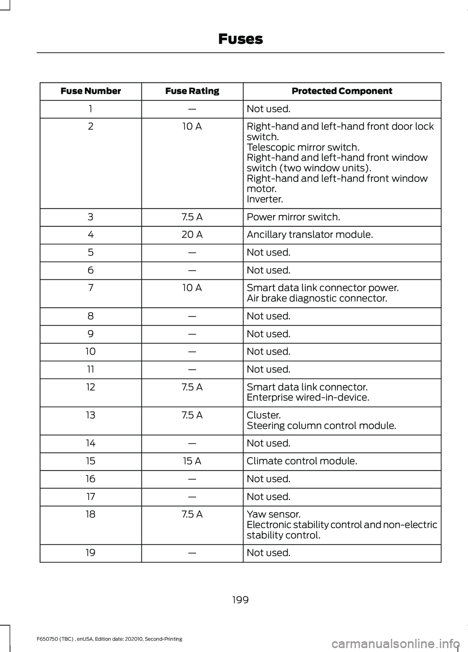
Protected Component
Fuse Rating
Fuse Number
Not used.
—
1
Right-hand and left-hand front door lock
switch.
10 A
2
Telescopic mirror switch.
Right-hand and left-hand front window
switch (two window units).
Right-hand and left-hand front window
motor.
Inverter.
Power mirror switch.
7.5 A
3
Ancillary translator module.
20 A
4
Not used.
—
5
Not used.
—
6
Smart data link connector power.
10 A
7
Air brake diagnostic connector.
Not used.
—
8
Not used.
—
9
Not used.
—
10
Not used.
—
11
Smart data link connector.
7.5 A
12
Enterprise wired-in-device.
Cluster.
7.5 A
13
Steering column control module.
Not used.
—
14
Climate control module.
15 A
15
Not used.
—
16
Not used.
—
17
Yaw sensor.
7.5 A
18
Electronic stability control and non-electric
stability control.
Not used.
—
19
199
F650750 (TBC) , enUSA, Edition date: 202010, Second-Printing Fuses
Page 207 of 390
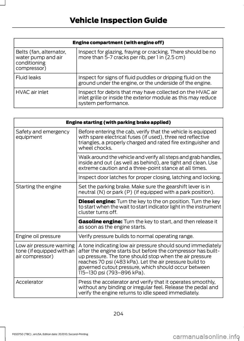
Engine compartment (with engine off)
Inspect for glazing, fraying or cracking. There should be no
more than 5-7 cracks per rib, per 1 in (2.5 cm)
Belts (fan, alternator,
water pump and air
conditioning
compressor)
Inspect for signs of fluid puddles or dripping fluid on the
ground under the engine, or the underside of the engine.
Fluid leaks
Inspect for debris that may have collected on the HVAC air
inlet grille or inside the exterior module as this may reduce
system performance.
HVAC air inlet Engine starting (with parking brake applied)
Before entering the cab, verify that the vehicle is equipped
with spare electrical fuses (if used), three red reflective
triangles, a properly charged and rated fire extinguisher and
wheel chocks.
Safety and emergency
equipment
Walk around the vehicle and verify all steps and grab handles,
inside and out (as well as behind), are tight and clean. Use
extreme caution and a three-point stance at all times.
Inspect door latches for proper closing, latching and locking.
Set the parking brake. Make sure the gearshift lever is in
neutral (N) or park (P) (if equipped with a park position).
Starting the engine
Diesel engine:
Turn the key to the on position. Turn the key
to start when the wait to start indicator light in the instrument
cluster turns off.
Gasoline engine:
Turn the key to start, and then release it
as soon as the engine starts.
Verify pressure builds to normal operating range.
Engine oil pressure
A tone indicating low air pressure should sound immediately
after the engine starts but before the compressor has built-
up pressure. The tone should stop when the air pressure
reaches
70 psi (483 kPa). Let the air pressure build to
governed cutout pressure, which should occur between
115– 130 psi (793–896 kPa)
.
Low air pressure warning
tone (if equipped with an
air compressor)
Press the accelerator and verify that it operates smoothly,
without any binding or irregular feel. Release the pedal and
verify the engine returns to idle speed immediately.
Accelerator
204
F650750 (TBC) , enUSA, Edition date: 202010, Second-Printing Vehicle Inspection Guide
Page 243 of 390
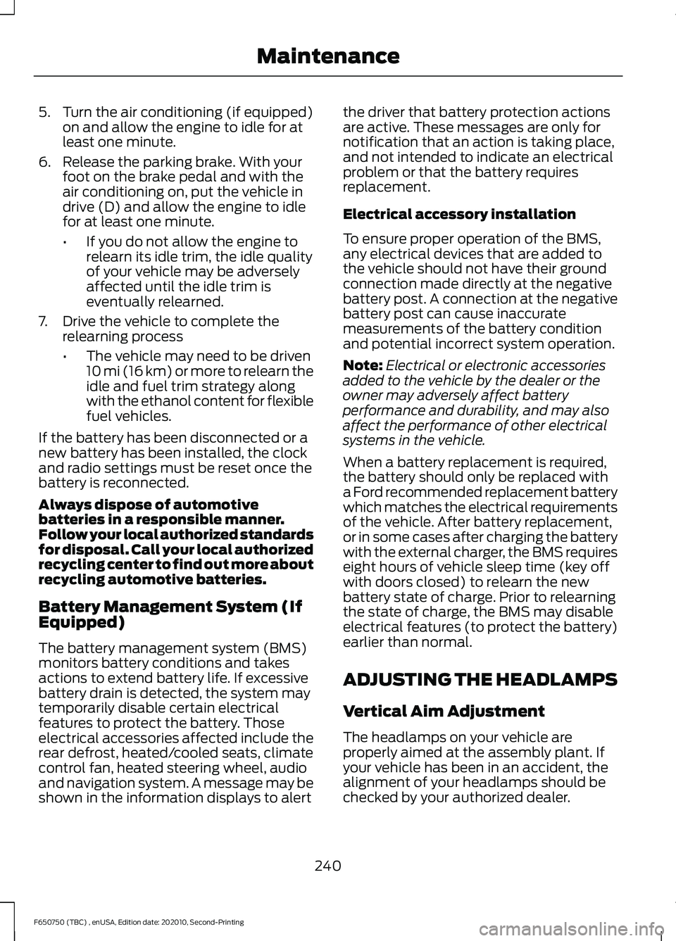
5. Turn the air conditioning (if equipped)
on and allow the engine to idle for at
least one minute.
6. Release the parking brake. With your foot on the brake pedal and with the
air conditioning on, put the vehicle in
drive (D) and allow the engine to idle
for at least one minute.
•If you do not allow the engine to
relearn its idle trim, the idle quality
of your vehicle may be adversely
affected until the idle trim is
eventually relearned.
7. Drive the vehicle to complete the relearning process
•The vehicle may need to be driven
10 mi (16 km) or more to relearn the
idle and fuel trim strategy along
with the ethanol content for flexible
fuel vehicles.
If the battery has been disconnected or a
new battery has been installed, the clock
and radio settings must be reset once the
battery is reconnected.
Always dispose of automotive
batteries in a responsible manner.
Follow your local authorized standards
for disposal. Call your local authorized
recycling center to find out more about
recycling automotive batteries.
Battery Management System (If
Equipped)
The battery management system (BMS)
monitors battery conditions and takes
actions to extend battery life. If excessive
battery drain is detected, the system may
temporarily disable certain electrical
features to protect the battery. Those
electrical accessories affected include the
rear defrost, heated/cooled seats, climate
control fan, heated steering wheel, audio
and navigation system. A message may be
shown in the information displays to alert the driver that battery protection actions
are active. These messages are only for
notification that an action is taking place,
and not intended to indicate an electrical
problem or that the battery requires
replacement.
Electrical accessory installation
To ensure proper operation of the BMS,
any electrical devices that are added to
the vehicle should not have their ground
connection made directly at the negative
battery post. A connection at the negative
battery post can cause inaccurate
measurements of the battery condition
and potential incorrect system operation.
Note:
Electrical or electronic accessories
added to the vehicle by the dealer or the
owner may adversely affect battery
performance and durability, and may also
affect the performance of other electrical
systems in the vehicle.
When a battery replacement is required,
the battery should only be replaced with
a Ford recommended replacement battery
which matches the electrical requirements
of the vehicle. After battery replacement,
or in some cases after charging the battery
with the external charger, the BMS requires
eight hours of vehicle sleep time (key off
with doors closed) to relearn the new
battery state of charge. Prior to relearning
the state of charge, the BMS may disable
electrical features (to protect the battery)
earlier than normal.
ADJUSTING THE HEADLAMPS
Vertical Aim Adjustment
The headlamps on your vehicle are
properly aimed at the assembly plant. If
your vehicle has been in an accident, the
alignment of your headlamps should be
checked by your authorized dealer.
240
F650750 (TBC) , enUSA, Edition date: 202010, Second-Printing Maintenance
Page 325 of 390
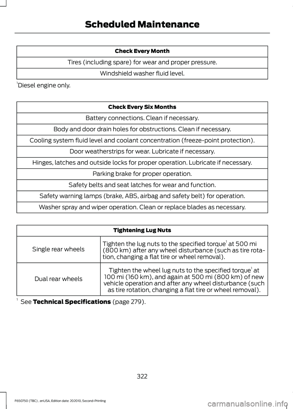
Check Every Month
Tires (including spare) for wear and proper pressure. Windshield washer fluid level.
1 Diesel engine only. Check Every Six Months
Battery connections. Clean if necessary.
Body and door drain holes for obstructions. Clean if necessary.
Cooling system fluid level and coolant concentration (freeze-point protection). Door weatherstrips for wear. Lubricate if necessary.
Hinges, latches and outside locks for proper operation. Lubricate if necessary. Parking brake for proper operation.
Safety belts and seat latches for wear and function.
Safety warning lamps (brake, ABS, airbag and safety belt) for operation.
Washer spray and wiper operation. Clean or replace blades as necessary. Tightening Lug Nuts
Tighten the lug nuts to the specified torque 1
at 500 mi
(800 km) after any wheel disturbance (such as tire rota-
tion, changing a flat tire or wheel removal).
Single rear wheels
Tighten the wheel lug nuts to the specified torque 1
at
100 mi (160 km)
, and again at 500 mi (800 km) of new
vehicle operation and after any wheel disturbance (such as tire rotation, changing a flat tire or wheel removal).
Dual rear wheels
1 See
Technical Specifications (page 279).
322
F650750 (TBC) , enUSA, Edition date: 202010, Second-Printing Scheduled Maintenance
Page 382 of 390
Changing the Engine-Mounted and
Diesel Fuel Conditioner Module Fuel
Filters - 6.7L Diesel...................................244
Diesel Fuel Conditioner Module Filter................................................................... 244
Engine-mounted Fuel Filter........................... 246
Changing the Engine Oil and Oil Filter................................................................219
Engine lubrication for severe service operation.......................................................... 220
Changing the Wiper Blades.....................242
Charging a Device...........................................91
Checking the Wiper Blades......................242
Child Restraint and Seatbelt Maintenance.................................................44
Child Restraint Positioning.........................34
Child Safety......................................................24
General Information............................................ 24
Child Safety Locks.........................................36
Cleaning Products
.......................................255
Materials............................................................... 255
Cleaning the Engine....................................257
Cleaning the Exterior
..................................256
Cleaning the Headlamps................................ 256
Exterior Chrome Parts..................................... 256
Exterior Plastic Parts........................................ 256
Stripes or Graphics............................................ 256
Underbody............................................................ 257
Under Hood.......................................................... 257
Cleaning the Instrument Panel and Instrument Cluster Lens
........................258
Cleaning the Interior...................................258
Mirrors.................................................................... 258
Cleaning the Wheels..................................259
Cleaning the Windows and Wiper Blades............................................................257
Climate Control
...............................................79
Cold Weather Precautions.........................177 Winter Operating Tips for Arctic Operation
-20°F (-29°C) and Below.......................... 179
Connected Vehicle
.....................................306
Connecting the Vehicle to a Mobile
Network........................................................... 306
Connected Vehicle Limitations..............306
Connected Vehicle Requirements
........306
Connected Vehicle – Troubleshooting.......................................306 Connecting a Bluetooth® Device...........312
Pairing a Device................................................... 312
Connecting the Vehicle to a Mobile Network.......................................................306
Connecting FordPass to the Connectivity Device............................................................... 306
Disabling the Connectivity Device..............306
What Is the Connectivity Device.................306
Coolant Check See: Engine Coolant Check - 6.7L Diesel....231
See: Engine Coolant Check - 7.3L................226
Cruise Control
................................................148
Cruise Control Indicators...........................155
Cruise Control - Vehicles With: Adaptive Cruise Control
...............................................52
Cruise Control - Vehicles With: Cruise Control.............................................................53
Customer Assistance
..................................187
D
Data Recording
.................................................13
Comfort, Convenience and Entertainment
Data....................................................................... 15
Event Data............................................................... 14
Service Data............................................................ 13
Services That Third Parties Provide...............15
Services That We Provide.................................. 15
Vehicles With a Connectivity Device..............15
Vehicles With an Emergency Call System................................................................. 16
Vehicles With SYNC............................................. 16
Daytime Running Lamps.............................57
Declaration of Conformity
........................376
Diesel Particulate Filter...............................116 Oxidation Catalytic Converter and Diesel
Particulate Filter System.............................. 117
Digital Radio
...................................................310
HD Radio Reception and Station
Troubleshooting.............................................. 311
Direction Indicators
.......................................58
Doors and Locks.............................................49
Draining the Fuel Filter Water Trap - 6.7L Diesel.............................................................225
Draining the Diesel Fuel Conditioner Module (DFCM)............................................................. 225
Driver Alert
......................................................156
Using Driver Alert................................................ 156
379
F650750 (TBC) , enUSA, Edition date: 202010, Second-Printing Index