service interval FORD F650/750 2021 Owners Manual
[x] Cancel search | Manufacturer: FORD, Model Year: 2021, Model line: F650/750, Model: FORD F650/750 2021Pages: 390, PDF Size: 5.16 MB
Page 11 of 390
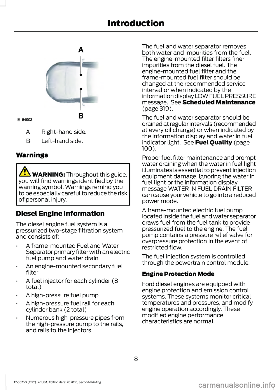
Right-hand side.
A
Left-hand side.
B
Warnings WARNING: Throughout this guide,
you will find warnings identified by the
warning symbol. Warnings remind you
to be especially careful to reduce the risk
of personal injury.
Diesel Engine Information
The diesel engine fuel system is a
pressurized two-stage filtration system
and consists of:
• A frame-mounted Fuel and Water
Separator primary filter with an electric
fuel pump and water drain
• An engine-mounted secondary fuel
filter
• A fuel injector for each cylinder (8
total)
• A high-pressure fuel pump
• A high-pressure fuel rail for each
cylinder bank (2 total)
• Numerous high-pressure pipes from
the high-pressure pump to the rails,
and rails to the injectors The fuel and water separator removes
both water and impurities from the fuel.
The engine-mounted filter filters finer
impurities from the diesel fuel. The
engine-mounted fuel filter and the
frame-mounted fuel filter should be
changed at the recommended service
interval or when indicated by the
information display LOW FUEL PRESSURE
message. See
Scheduled Maintenance
(page 319).
The fuel and water separator should be
drained at regular intervals (recommended
at every oil change) or when indicated by
the information display and water in fuel
indicator light. See
Fuel Quality (page
100).
Proper fuel filter maintenance and prompt
water draining when the water in fuel light
illuminates is essential to prevent injection
equipment damage. Ignoring the water in
fuel light or the information display
message WATER IN FUEL DRAIN FILTER
can cause your vehicle to go into a reduced
power mode.
A frame-mounted electric fuel pump
located inside the fuel and water separator
draws fuel from the fuel tank to provide
pressurized fuel to the engine. The fuel
pump contains a pressure relief valve for
overpressure protection in the event of
restricted flow.
The fuel injection system is controlled
through the powertrain control module.
Engine Protection Mode
Ford diesel engines are equipped with
engine protection and emission control
systems. These systems monitor critical
temperatures and pressures, and modify
engine operation accordingly. These
modified engine performance
characteristics are normal.
8
F650750 (TBC) , enUSA, Edition date: 202010, Second-Printing IntroductionE154903
Page 12 of 390
If these modified engine performance
characteristics persist for an extended
period and either the service engine soon
or powertrain malfunction, reduced power,
electronic throttle control light is
illuminated, have the system checked by
an authorized dealer.
Service engine soon
Powertrain malfunction, reduced
power, electronic throttle control
Diesel Lubrication System
It is important to change the engine oil at
the recommended service intervals or
when indicated by the information display
to maintain oil viscosity. Extending the oil
and filter change interval beyond the
recommended interval can negatively
affect engine performance, fuel economy
and engine life. See Engine Oil Check
(page 218).
Engine and secondary cooling system
The cooling system contains a primary
cooling loop to cool the engine and a
secondary cooling loop to cool the
transmission, charge air, and fuel. The
coolant serves three primary purposes: to
provide heat transfer, freeze point
protection, and corrosion protection using
additives.
Vehicles with diesel engines typically are
used to carry heavy loads and accumulate
mileage rapidly. These two factors may
cause the additives in the coolant to wear
out in a shorter time. You can find more
information about coolant additives and
coolant change intervals in the coolant
chapter. See
General Maintenance
Information (page 319). Operating the
engine with insufficient coolant or coolant
additive can cause severe engine damage. Selective catalytic reduction system
Your vehicle is equipped with a selective
catalytic reduction system designed to
reduce emission levels of nitrogen oxides
from the exhaust of your diesel engine. This
system relies on the use of Diesel Exhaust
Fluid (DEF) that you must replenish at
certain intervals. Failure to maintain proper
DEF levels or if the DEF becomes
contaminated will result in vehicle speed
limitations or result in your vehicle entering
an idle-only mode. See
Selective
Catalytic Reductant System (page 112).
Minor Troubleshooting Guide
If the engine won ’t crank WARNING:
Battery posts,
terminals and related accessories
contain lead and lead compounds. Wash
hands after handling.
Turn on the headlights. If the lights are dim,
do not go on at all or when the ignition is
turned to the start position, the lights
become dim or go out, the battery
connections may be loose or corroded, or
the battery may be discharged. If there is
a clicking or stuttering sound coming from
the engine compartment when you turn
the key to the start position, this may also
indicate a loose or corroded battery
connection.
Check the battery connections at the
battery posts, cable connection to the
engine grounding point and at the starter
connection.
If you suspect a discharged battery, have
it checked and corrected.
9
F650750 (TBC) , enUSA, Edition date: 202010, Second-Printing Introduction
Page 105 of 390
To help achieve acceptable engine
performance and durability when using
biodiesel in your vehicle:
•
Confirm the biodiesel content of the
fuel to be 20% biodiesel or less, also
known as B20.
• Only use biodiesel fuel of good quality
that complies with industry standards.
• Follow the recommended service
maintenance intervals. See
Scheduled Maintenance (page 319).
• Do not store biodiesel fuel in the fuel
tank for more than 1 month.
• Consider changing brands or reducing
biodiesel content if you have cold
temperature fuel gelling issues or a
frequent LOW FUEL PRESSURE
message appearing.
Note: Do not use home heating oil,
agricultural fuel, raw fats and oils, waste
cooking greases, biodiesel fuels greater than
20% or any diesel fuel not intended for
highway use. Red dye is used to identify
fuels intended for agricultural and
non-highway use. Damage to the fuel
injection system, engine and exhaust
catalyst can occur if an improper fuel is
used.
Use of biodiesel in concentrations greater
than 20% could cause damage to your
vehicle, including engine and/or exhaust
catalyst and particulate filter failures.
Concentrations greater than 20% can also
cause fuel filter restrictions that could
result in a lack of power or damage to fuel
system components, including fuel pump
and fuel injector failures.
SAE 5W-40 or SAE 15W-40 oil is
recommended for fuels with greater than
5% biodiesel, also known as B5. Follow
the recommended oil change intervals and
other maintenance when operating on
biodiesel. See
Special Operating
Conditions Scheduled Maintenance
(page
329). Look for a label on the fuel pump to
confirm the amount of biodiesel contained
in a diesel fuel. Biodiesel content is often
indicated with the letter B followed by the
percent of biodiesel in the fuel. For
example, B20 indicates a fuel containing
20% biodiesel. Ask the service station
attendant to confirm the biodiesel content
of a diesel fuel if you do not see a label on
the fuel pump.
Note:
Biodiesel fuels degrade more easily
than diesel fuels not containing biodiesel.
Degraded or oxidized biodiesel can damage
fuel system seals and plastics and corrode
steel parts. If you plan to park or store your
vehicle for more than 1 month, empty your
vehicle fuel tank of biodiesel fuel. Fill the
tank with a pure petroleum-based diesel
fuel and run your vehicle for a minimum of
30 minutes.
During cold weather, if you have problems
operating on biodiesel, you may need to
use a diesel fuel with lower biodiesel
content, try another brand, or discontinue
the use of biodiesel.
Diesel Fuel Additives
It should not be necessary to add any
aftermarket additives to your fuel if you
use a high quality diesel fuel that conforms
to ASTM industry specifications.
Aftermarket additives can damage the fuel
injector system or engine.
Use Motorcraft® cetane booster or an
equivalent cetane booster additive if you
suspect fuel has low cetane. Use
Motorcraft® anti-gel & performance
improver or an equivalent additive if there
is fuel gelling.
Do not use alcohol-based additives to
improve cetane quality, to prevent fuel
gelling or any other use. The use of alcohol
additives may result in damage to the fuel
injectors and system. See Capacities and
Specifications (page 288).
102
F650750 (TBC) , enUSA, Edition date: 202010, Second-Printing Fuel and Refueling
Page 139 of 390
Cam Brakes - Automatic Slack
Adjusters
WARNING: Do not manually adjust
the automatic slack adjusters to correct
excessive push rod stroke as it may result
in reduced brake effectiveness and a
vehicle crash. Excessive push rod stroke
indicates that a problem exists with the
automatic adjuster, with the installation
of the adjuster, or with foundation brake
components that manual adjustment
does not remedy. Seek service from a
qualified facility for excessive push rod
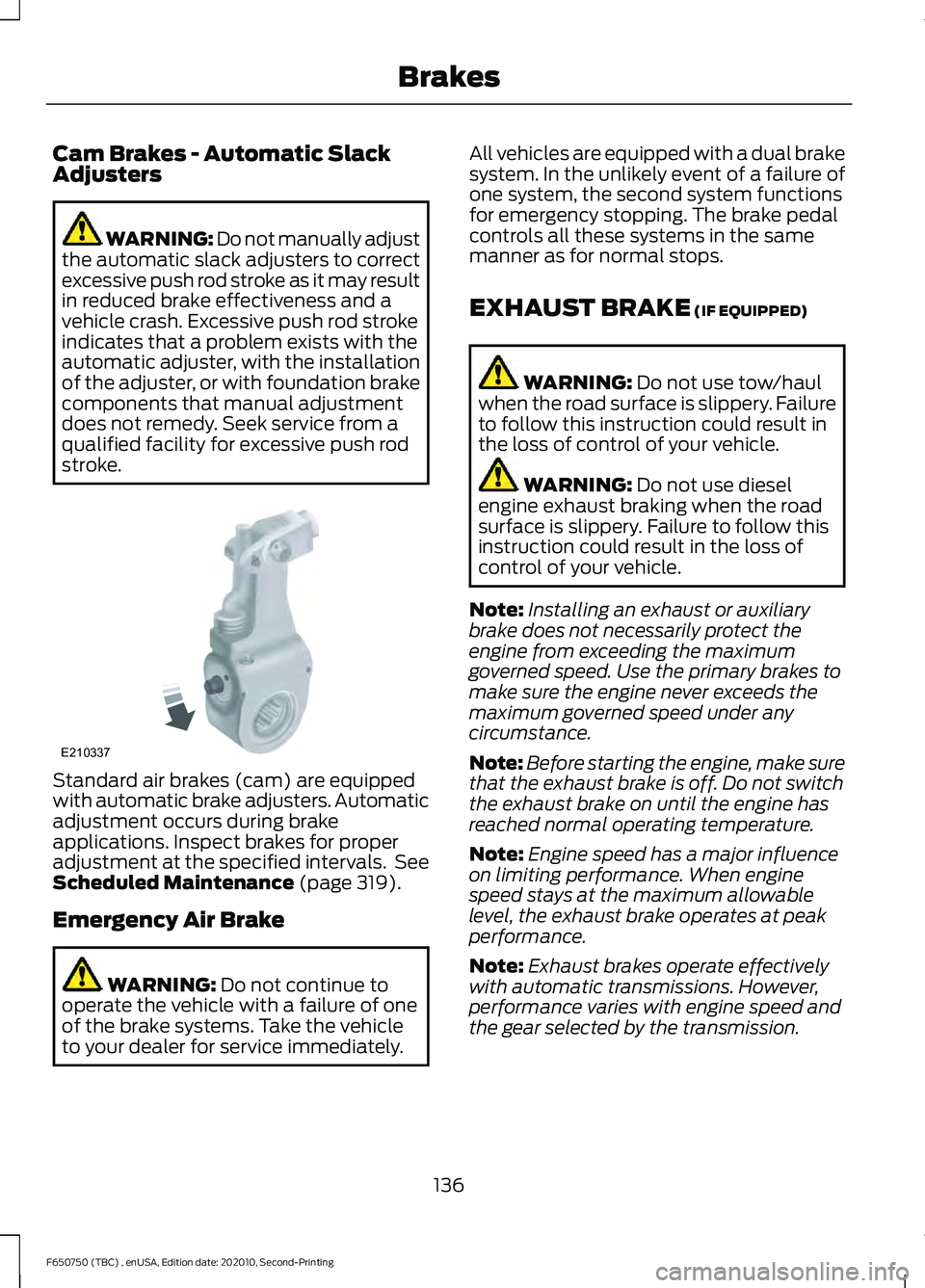
stroke. Standard air brakes (cam) are equipped
with automatic brake adjusters. Automatic
adjustment occurs during brake
applications. Inspect brakes for proper
adjustment at the specified intervals. See
Scheduled Maintenance (page 319).
Emergency Air Brake WARNING:
Do not continue to
operate the vehicle with a failure of one
of the brake systems. Take the vehicle
to your dealer for service immediately. All vehicles are equipped with a dual brake
system. In the unlikely event of a failure of
one system, the second system functions
for emergency stopping. The brake pedal
controls all these systems in the same
manner as for normal stops.
EXHAUST BRAKE
(IF EQUIPPED)
WARNING:
Do not use tow/haul
when the road surface is slippery. Failure
to follow this instruction could result in
the loss of control of your vehicle. WARNING:
Do not use diesel
engine exhaust braking when the road
surface is slippery. Failure to follow this
instruction could result in the loss of
control of your vehicle.
Note: Installing an exhaust or auxiliary
brake does not necessarily protect the
engine from exceeding the maximum
governed speed. Use the primary brakes to
make sure the engine never exceeds the
maximum governed speed under any
circumstance.
Note: Before starting the engine, make sure
that the exhaust brake is off. Do not switch
the exhaust brake on until the engine has
reached normal operating temperature.
Note: Engine speed has a major influence
on limiting performance. When engine
speed stays at the maximum allowable
level, the exhaust brake operates at peak
performance.
Note: Exhaust brakes operate effectively
with automatic transmissions. However,
performance varies with engine speed and
the gear selected by the transmission.
136
F650750 (TBC) , enUSA, Edition date: 202010, Second-Printing BrakesE210337
Page 222 of 390
Adding Engine Oil
WARNING: Do not remove the filler
cap when the engine is running.
Do not use supplemental engine oil
additives because they are unnecessary
and could lead to engine damage that may
not be covered by the vehicle Warranty.
To top up the engine oil level do the
following:
1. Clean the area surrounding the engine oil filler cap before you remove it.
2. Remove the engine oil filler cap. See Under Hood Overview (page 215).
Turn it counterclockwise and remove
it.
3. Add engine oil of the proper viscosity and grade that meets Ford
specifications. See
Capacities and
Specifications (page 288). You may
have to use a funnel to pour the engine
oil into the opening.
4. Recheck the oil level.
5. If the oil level is correct, replace the dipstick and make sure it is fully seated.
6. Replace the engine oil filler cap. Turn it clockwise until you feel a strong
resistance.
Note: Do not add oil further than the
maximum mark. Oil levels above the
maximum mark may cause engine damage.
Note: Make sure you install the oil filler cap
correctly.
Note: Soak up any spillage with an
absorbent cloth immediately. Engine lubrication for severe
service operation
The following conditions define severe
operation for which engine operation with
SAE 5W-40 oil which meets Ford
specification, WSS-M2C171-F1, is
recommended. Oil and oil filter change
intervals will be determined by the
Intelligent Oil Life Monitor™ as noted
previously.
CHANGING THE ENGINE OIL
AND OIL FILTER
WARNING: Do not handle a hot oil
filter with bare hands. WARNING:
Continuous contact
with used motor oil has caused cancer
in laboratory mice. Protect your skin by
washing with soap and water.
If your vehicle is equipped with a diesel
engine, an Intelligent Oil Life Monitor™
calculates the proper oil change service
interval. When the information display
indicates: OIL CHANGE REQUIRED, change
the engine oil and oil filter. See
Information Displays
(page 70).
The engine oil filter protects your engine
by filtering harmful, abrasive or sludge
particles and particles significantly smaller
than most available will-fit filters. See
Motorcraft Parts
(page 283).
1. Unscrew the oil filter and oil pan drain plug and wait for the oil to drain.
2. Replace the filter.
3. Reinstall the oil pan drain plug.
4. Refill the engine with new oil. See Capacities and Specifications (page
288
).
219
F650750 (TBC) , enUSA, Edition date: 202010, Second-Printing Maintenance
Page 223 of 390
5. For diesel engines, you need to reset
the Intelligent Oil Life Monitor™. See
Information Displays (page 70).
Engine lubrication for severe
service operation
The following conditions define severe
operation for which engine operation with
SAE 5W-40 API CJ-4 is recommended. Oil
and oil filter change intervals will be
determined by the Intelligent Oil Life
Monitor™ as noted previously.
• Frequent or extended idling (over 10
minutes per hour of normal driving).
• Low-speed operation/stationary use.
• If vehicle is operated in sustained
ambient temperatures below
-9°F
(-23°C) or above 100°F (38°C).
• Frequent low-speed operation,
consistent heavy traffic less than
25 mph (40 km/h)
.
• Operating in severe dust conditions.
• Operating the vehicle off road.
• Towing a trailer over
1,000 mi
(1,600 km).
• Sustained, high-speed driving at Gross
Vehicle Weight Rating (maximum
loaded weight for vehicle operation).
• Use of fuels with sulfur content other
than ultra-low sulfur diesel (ULSD).
• Use of high-sulfur diesel fuel.
OIL CHANGE INDICATOR
RESET
Base Cluster
Use the information display controls on
the steering wheel to reset the oil change
indicator. From the main menu scroll to: Action and Description
Message
Press the right arrow button,
then from this menu scroll
to the following message.
Settings
Press the down arrow
button, then from this menu
scroll to the following
message.
Vehicle
Press the right arrow button,
then from this menu scroll
to the following message.
Oil Life
Reset
Press and hold the
OK
button until the instrument
cluster displays the
following message.
Oil Life
Hold to
Reset
Press and hold the
OK
button until the instrument
cluster displays the
following message.
Oil Life
Hold OK
to Reset
Reset Complete
If the instrument cluster
displays the following
message, repeat the
process.
Reset Cancelled
High Series Cluster
Use the information display controls on
the steering wheel to reset the oil change
indicator.
220
F650750 (TBC) , enUSA, Edition date: 202010, Second-Printing Maintenance
Page 229 of 390
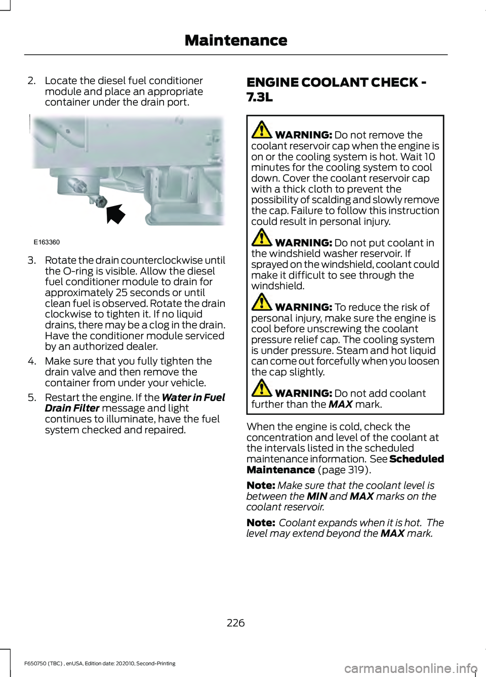
2. Locate the diesel fuel conditioner
module and place an appropriate
container under the drain port. 3.
Rotate the drain counterclockwise until
the O-ring is visible. Allow the diesel
fuel conditioner module to drain for
approximately 25 seconds or until
clean fuel is observed. Rotate the drain
clockwise to tighten it. If no liquid
drains, there may be a clog in the drain.
Have the conditioner module serviced
by an authorized dealer.
4. Make sure that you fully tighten the drain valve and then remove the
container from under your vehicle.
5. Restart the engine. If the Water in Fuel
Drain Filter message and light
continues to illuminate, have the fuel
system checked and repaired. ENGINE COOLANT CHECK -
7.3L WARNING:
Do not remove the
coolant reservoir cap when the engine is
on or the cooling system is hot. Wait 10
minutes for the cooling system to cool
down. Cover the coolant reservoir cap
with a thick cloth to prevent the
possibility of scalding and slowly remove
the cap. Failure to follow this instruction
could result in personal injury. WARNING:
Do not put coolant in
the windshield washer reservoir. If
sprayed on the windshield, coolant could
make it difficult to see through the
windshield. WARNING:
To reduce the risk of
personal injury, make sure the engine is
cool before unscrewing the coolant
pressure relief cap. The cooling system
is under pressure. Steam and hot liquid
can come out forcefully when you loosen
the cap slightly. WARNING:
Do not add coolant
further than the MAX mark.
When the engine is cold, check the
concentration and level of the coolant at
the intervals listed in the scheduled
maintenance information. See Scheduled
Maintenance
(page 319).
Note: Make sure that the coolant level is
between the
MIN and MAX marks on the
coolant reservoir.
Note: Coolant expands when it is hot. The
level may extend beyond the
MAX mark.
226
F650750 (TBC) , enUSA, Edition date: 202010, Second-Printing MaintenanceE163360
Page 239 of 390
AUTOMATIC TRANSMISSION
FLUID CHECK
The transmission does not consume fluid.
However, check the fluid level if the
transmission is not working properly, for
example if the transmission slips, shifts
slowly or if there are signs of fluid loss.
Replace the transmission fluid and filter
on your vehicle at the specified service
interval. See Scheduled Maintenance
(page 319).
Automatic transmission fluid expands
when warmed. To check the fluid level
consistently and accurately, do the
following:
1. Drive the vehicle until it reaches normal
operating temperature. This may take
up to
20 mi (30 km). Make sure that
the transmission fluid temperature
gauge on the instrument cluster is
within normal operating temperature
196– 215°F (91– 102°C)
before
checking.
2. Make sure that your vehicle is on level ground.
3. With the engine running, parking brake
engaged and your foot on the brake
pedal, move the gearshift lever through
all of the gear ranges. Allow sufficient
time for each gear to engage.
4. Make sure the parking brake is on. Make
sure the transmission is in park (P) or
neutral (N) and leave the engine
running.
5. Open the hood. See
Opening and
Closing the Hood (page 213).
6. Remove the dipstick and wipe it with a clean, lint-free cloth. See
Under
Hood Overview (page 215).
7. Replace the dipstick and remove it again to check the fluid level. 8. If the fluid level is correct, replace the
dipstick and make sure it is fully seated.
Note: If the fluid level is between the
maximum and minimum marks, the fluid
level is acceptable. Do not add fluid.
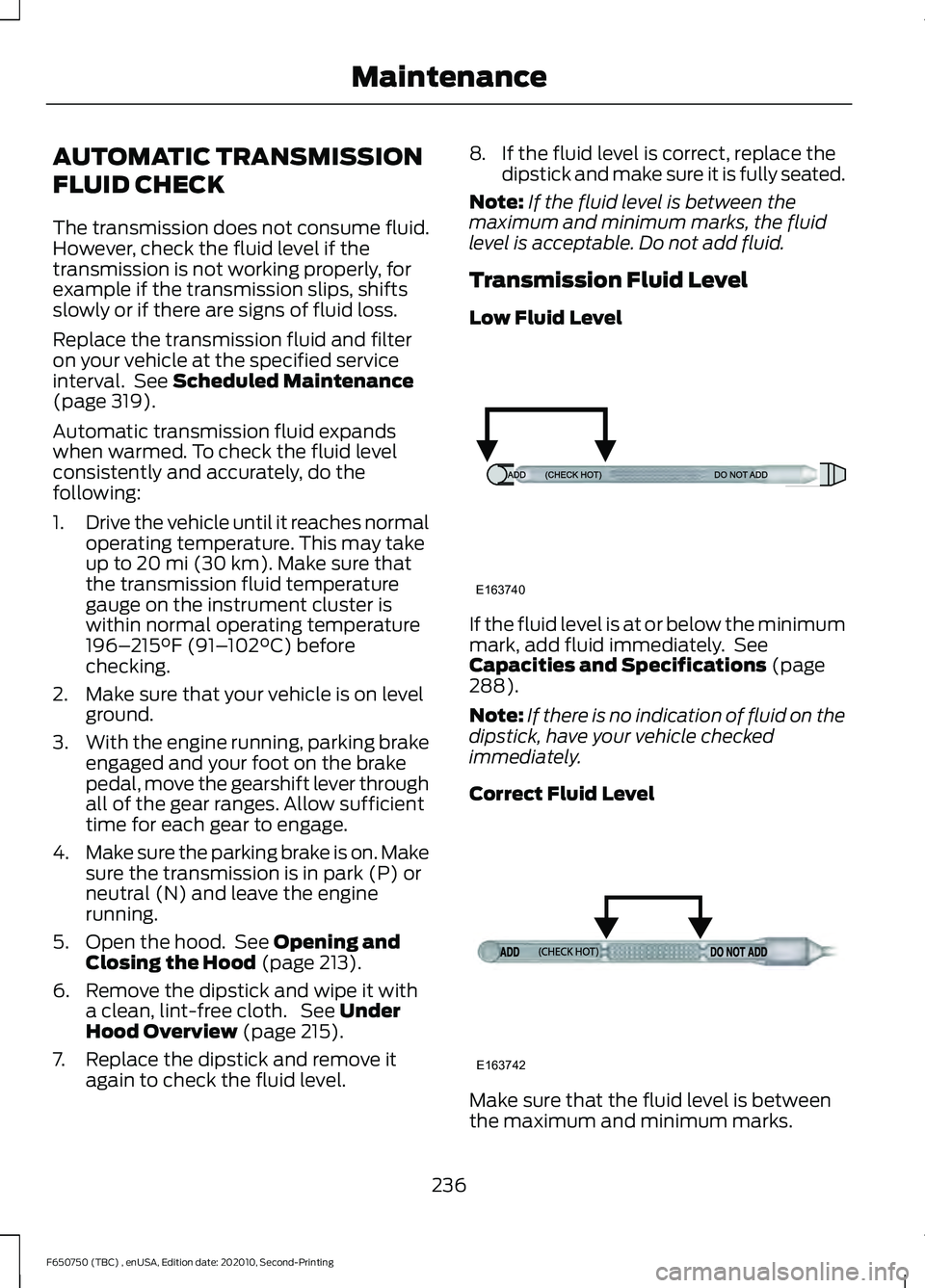
Transmission Fluid Level
Low Fluid Level If the fluid level is at or below the minimum
mark, add fluid immediately. See
Capacities and Specifications
(page
288).
Note: If there is no indication of fluid on the
dipstick, have your vehicle checked
immediately.
Correct Fluid Level Make sure that the fluid level is between
the maximum and minimum marks.
236
F650750 (TBC) , enUSA, Edition date: 202010, Second-Printing MaintenanceE163740 E163742
Page 241 of 390
1. Park your vehicle on a level surface.
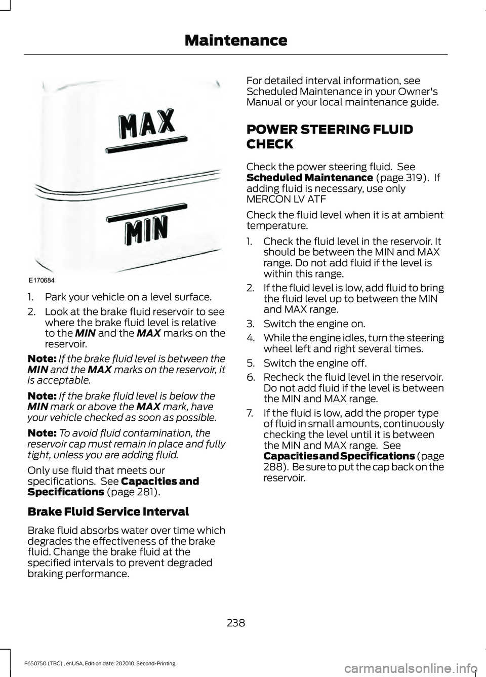
2. Look at the brake fluid reservoir to see
where the brake fluid level is relative
to the MIN and the MAX marks on the
reservoir.
Note: If the brake fluid level is between the
MIN
and the MAX marks on the reservoir, it
is acceptable.
Note: If the brake fluid level is below the
MIN
mark or above the MAX mark, have
your vehicle checked as soon as possible.
Note: To avoid fluid contamination, the
reservoir cap must remain in place and fully
tight, unless you are adding fluid.
Only use fluid that meets our
specifications. See
Capacities and
Specifications (page 281).
Brake Fluid Service Interval
Brake fluid absorbs water over time which
degrades the effectiveness of the brake
fluid. Change the brake fluid at the
specified intervals to prevent degraded
braking performance. For detailed interval information, see
Scheduled Maintenance in your Owner's
Manual or your local maintenance guide.
POWER STEERING FLUID
CHECK
Check the power steering fluid. See
Scheduled Maintenance
(page 319). If
adding fluid is necessary, use only
MERCON LV ATF
Check the fluid level when it is at ambient
temperature.
1. Check the fluid level in the reservoir. It should be between the MIN and MAX
range. Do not add fluid if the level is
within this range.
2. If the fluid level is low, add fluid to bring
the fluid level up to between the MIN
and MAX range.
3. Switch the engine on.
4. While the engine idles, turn the steering
wheel left and right several times.
5. Switch the engine off.
6. Recheck the fluid level in the reservoir. Do not add fluid if the level is between
the MIN and MAX range.
7. If the fluid is low, add the proper type of fluid in small amounts, continuously
checking the level until it is between
the MIN and MAX range. See
Capacities and Specifications (page
288). Be sure to put the cap back on the
reservoir.
238
F650750 (TBC) , enUSA, Edition date: 202010, Second-Printing MaintenanceE170684
Page 247 of 390
Brake Lamp, Rear Lamp, Rear
Direction Indicator, License Plate
Lamp and Reverse Lamp
1.
Switch all of the lamps and the ignition
off.
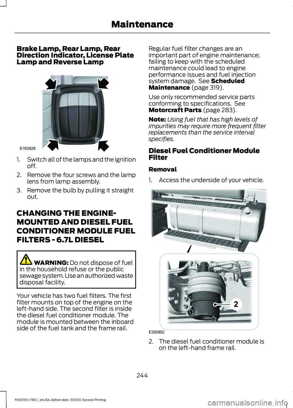
2. Remove the four screws and the lamp lens from lamp assembly.
3. Remove the bulb by pulling it straight out.
CHANGING THE ENGINE-
MOUNTED AND DIESEL FUEL
CONDITIONER MODULE FUEL
FILTERS - 6.7L DIESEL WARNING: Do not dispose of fuel
in the household refuse or the public
sewage system. Use an authorized waste
disposal facility.
Your vehicle has two fuel filters. The first
filter mounts on top of the engine on the
left-hand side. The second filter is inside
the diesel fuel conditioner module. The
module is mounted between the inboard
side of the fuel tank and the frame rail. Regular fuel filter changes are an
important part of engine maintenance;
failing to keep with the scheduled
maintenance could lead to engine
performance issues and fuel injection
system damage. See
Scheduled
Maintenance (page 319).
Use only recommended service parts
conforming to specifications. See
Motorcraft Parts
(page 283).
Note: Using fuel that has high levels of
impurities may require more frequent filter
replacements than the service interval
specifies.
Diesel Fuel Conditioner Module
Filter
Removal
1. Access the underside of your vehicle. 2. The diesel fuel conditioner module is
on the left-hand frame rail.
244
F650750 (TBC) , enUSA, Edition date: 202010, Second-Printing MaintenanceE163828 E250852