AUX FORD F650/750 2023 Owners Manual
[x] Cancel search | Manufacturer: FORD, Model Year: 2023, Model line: F650/750, Model: FORD F650/750 2023Pages: 378, PDF Size: 5.65 MB
Page 6 of 378
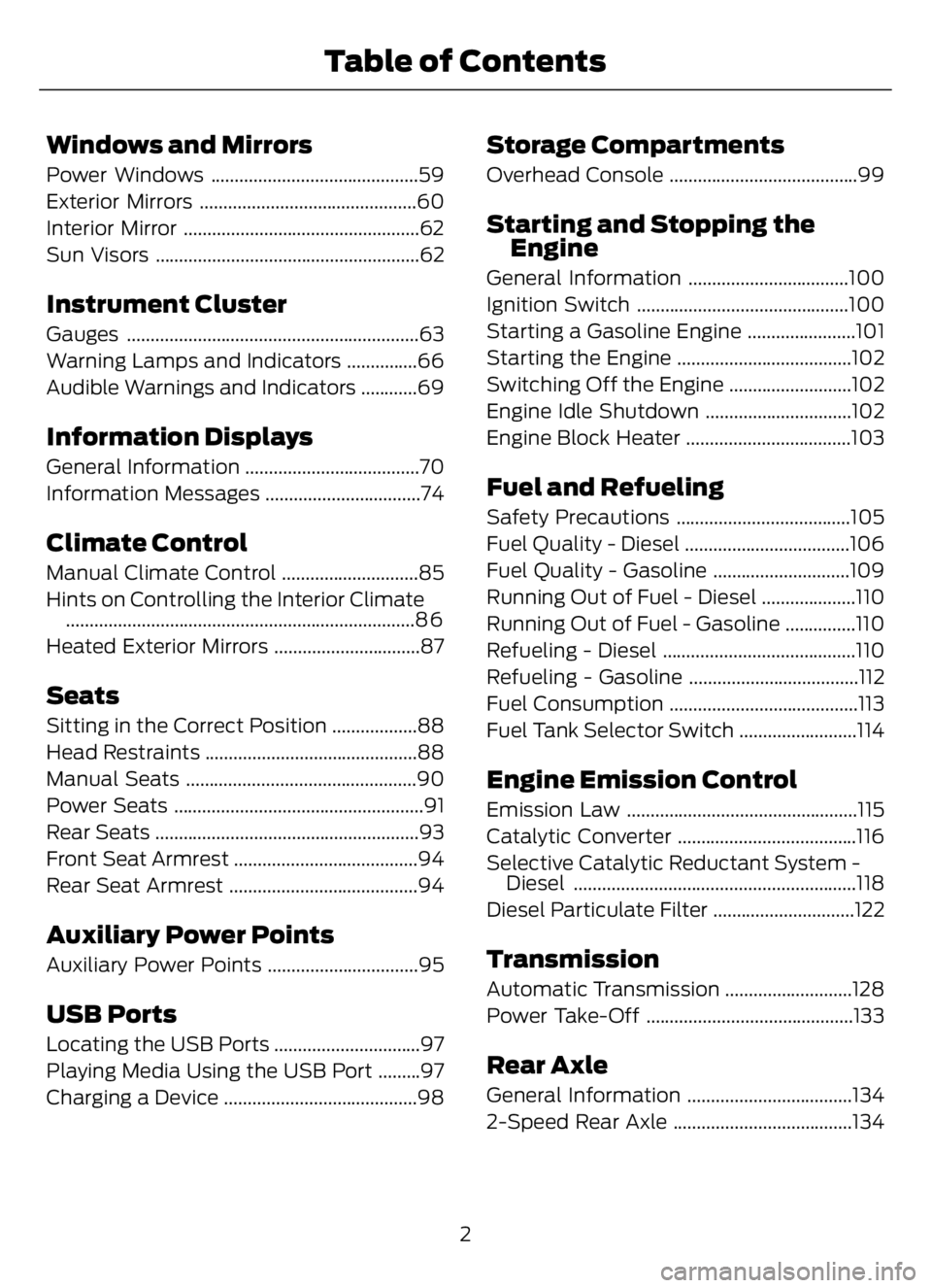
Windows and Mirrors
Power Windows ............................................59
Exterior Mirrors ..............................................60
Interior Mirror ..................................................62
Sun Visors ........................................................62
Instrument Cluster
Gauges ..............................................................63
Warning Lamps and Indicators ...............66
Audible Warnings and Indicators ............69
Information Displays
General Information .....................................70
Information Messages .................................74
Climate Control
Manual Climate Control .............................85
Hints on Controlling the Interior Climate
..........................................................................8 6
Heated Exterior Mirrors ...............................87
Seats
Sitting in the Correct Position ..................88
Head Restraints .............................................88
Manual Seats .................................................90
Power Seats .....................................................91
Rear Seats ........................................................93
Front Seat Armrest .......................................94
Rear Seat Armrest ........................................94
Auxiliary Power Points
Auxiliary Power Points ................................95
USB Ports
Locating the USB Ports ...............................97
Playing Media Using the USB Port .........97
Charging a Device .........................................98
Storage Compartments
Overhead Console ........................................99
Starting and Stopping the
Engine
General Information ..................................100
Ignition Switch .............................................100
Starting a Gasoline Engine .......................101
Starting the Engine .....................................102
Switching Off the Engine ..........................102
Engine Idle Shutdown ...............................102
Engine Block Heater ...................................103
Fuel and Refueling
Safety Precautions .....................................105
Fuel Quality - Diesel ...................................106
Fuel Quality - Gasoline .............................109
Running Out of Fuel - Diesel ....................110
Running Out of Fuel - Gasoline ...............110
Refueling - Diesel .........................................110
Refueling - Gasoline ....................................112
Fuel Consumption ........................................113
Fuel Tank Selector Switch .........................114
Engine Emission Control
Emission Law .................................................115
Catalytic Converter ......................................116
Selective Catalytic Reductant System -
Diesel ............................................................118
Diesel Particulate Filter ..............................122
Transmission
Automatic Transmission ...........................128
Power Take-Off ............................................133
Rear Axle
General Information ...................................134
2-Speed Rear Axle ......................................134
2
Table of Contents
Page 9 of 378
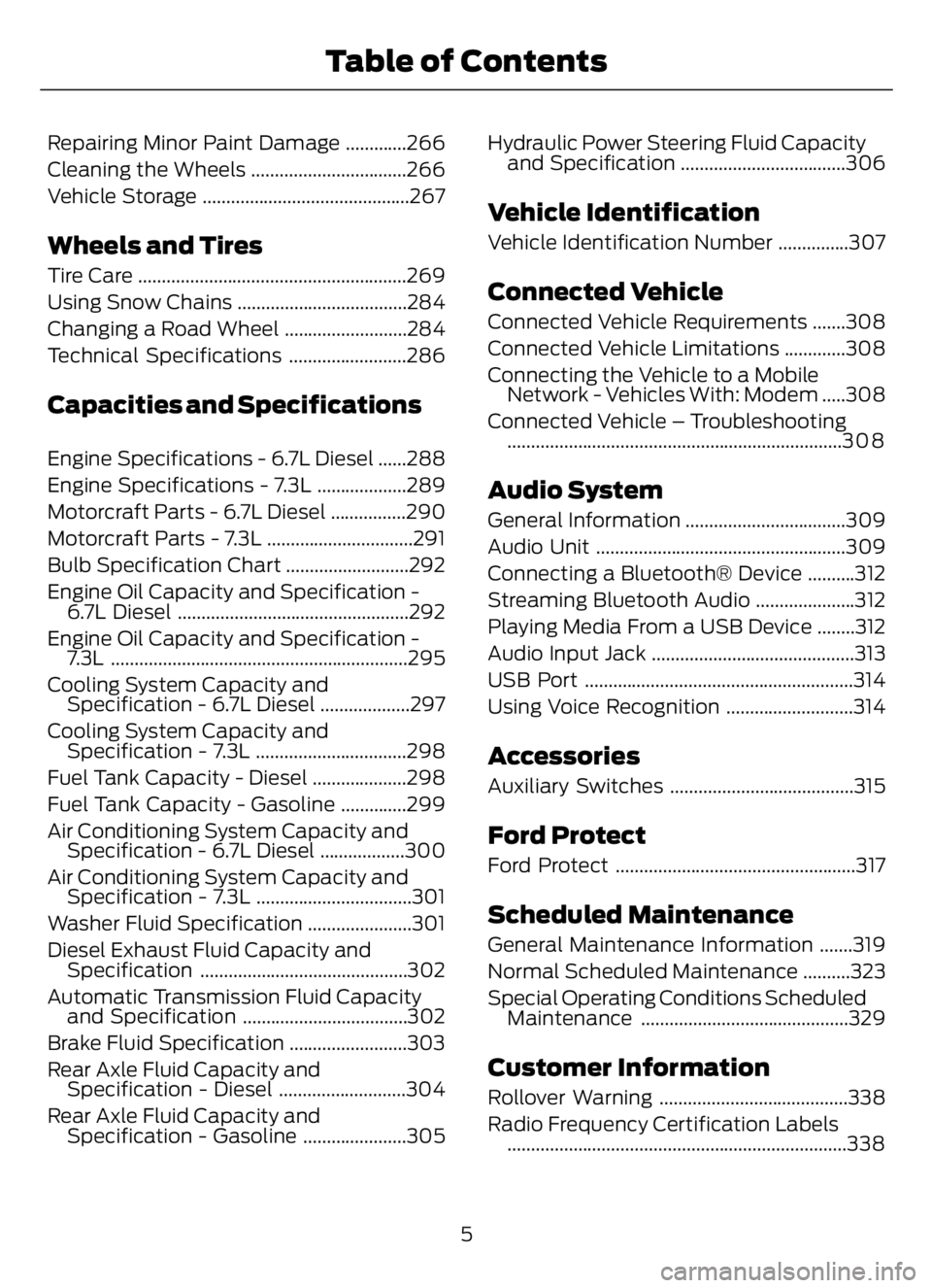
Repairing Minor Paint Damage .............266
Cleaning the Wheels .................................266
Vehicle Storage ............................................267
Wheels and Tires
Tire Care .........................................................269
Using Snow Chains ....................................284
Changing a Road Wheel ..........................284
Technical Specifications .........................286
Capacities and Specifications
Engine Specifications - 6.7L Diesel ......288
Engine Specifications - 7.3L ...................289
Motorcraft Parts - 6.7L Diesel ................290
Motorcraft Parts - 7.3L ...............................291
Bulb Specification Chart ..........................292
Engine Oil Capacity and Specification -
6.7L Diesel .................................................292
Engine Oil Capacity and Specification -
7.3L ...............................................................295
Cooling System Capacity and
Specification - 6.7L Diesel ...................297
Cooling System Capacity and
Specification - 7.3L ................................298
Fuel Tank Capacity - Diesel ....................298
Fuel Tank Capacity - Gasoline ..............299
Air Conditioning System Capacity and
Specification - 6.7L Diesel ..................300
Air Conditioning System Capacity and
Specification - 7.3L .................................301
Washer Fluid Specification ......................301
Diesel Exhaust Fluid Capacity and
Specification ............................................302
Automatic Transmission Fluid Capacity
and Specification ...................................302
Brake Fluid Specification .........................303
Rear Axle Fluid Capacity and
Specification - Diesel ...........................304
Rear Axle Fluid Capacity and
Specification - Gasoline ......................305Hydraulic Power Steering Fluid Capacity
and Specification ...................................306
Vehicle Identification
Vehicle Identification Number ...............307
Connected Vehicle
Connected Vehicle Requirements .......308
Connected Vehicle Limitations .............308
Connecting the Vehicle to a Mobile
Network - Vehicles With: Modem .....308
Connected Vehicle – Troubleshooting
.......................................................................3 0 8
Audio System
General Information ..................................309
Audio Unit .....................................................309
Connecting a Bluetooth® Device ..........312
Streaming Bluetooth Audio .....................312
Playing Media From a USB Device ........312
Audio Input Jack ...........................................313
USB Port .........................................................314
Using Voice Recognition ...........................314
Accessories
Auxiliary Switches .......................................315
Ford Protect
Ford Protect ...................................................317
Scheduled Maintenance
General Maintenance Information .......319
Normal Scheduled Maintenance ..........323
Special Operating Conditions Scheduled
Maintenance ............................................329
Customer Information
Rollover Warning ........................................338
Radio Frequency Certification Labels
........................................................................338
5
Table of Contents
Page 14 of 378
• The gearshift lever must be in P (Park)
or N (Neutral) in order for the starter
to operate.
• Try operating the starter switch several
times. This operation may clean
potentially corroded contacts or make
the switch temporarily operable until
you can reach the dealer.
• If all electrical connections are tight
and you need assistance to start, See
Jump Starting the Vehicle (page 190).
If engine cranks but won’t start
Prolonged starter cranking (in excess of 10
seconds) could cause damage to the
starter motor or the high-pressure fuel
pump.
• Check the fuel gauge. You may be out
of fuel. If the gauge shows that there
is fuel in the tank, the trouble may be
in the electrical system or the fuel
system. If equipped with an auxiliary
tank, be sure that the tank control
switch is set for the tank with fuel and
not on an empty tank.
• Leaving your ignition key turned to on
for over two minutes without starting
may make starting difficult because
the glow plugs will cease activation.
Reset the system by turning the ignition
key to off and then back to on again.
Note:If the system is out of fuel and the
engine will not start, do not continue
cranking the engine. Continued cranking can
damage the high-pressure fuel pump.
If the engine runs hot
The following could cause the engine to
overheat:
• Lack of coolant
• Dirty cooling system.
• Plugged radiator fins, A/C condenser
and/or oil cooler
• Malfunctioning fan drive• Driving with frozen coolant
• Sticking thermostat
• Overloading or pulling heavy trailers
during hot weather
• Grill or radiator air blockage
• Slipping or missing drive belt
• Plugged or very dirty air filter
If fuses burn out
WARNING: Replacement fuses and
circuit breakers must always be the
same rating as the original equipment
shown. Never replace a fuse or circuit
breaker with one of a higher rating.
Higher rated fuses or circuit breakers
could allow circuit overloading in the
event of a circuit malfunction, resulting
in severe vehicle damage or personal
injury due to fire.
Burned-out or blown fuses usually indicate
an electrical short-circuit, although a fuse
may occasionally burn out from vibration.
Insert a second fuse. If this fuse
immediately burns out and you cannot
locate the cause, return your vehicle to
your dealer for a circuit check. See
Changing a Fuse (page 208).
Selective catalytic reduction system
speed limit and Idle-only modes
If the vehicle’s speed is limited or in an
idle-only mode, the selective catalytic
reduction system may be limiting the
vehicle’s functions due to low or
contaminated DEF. Check the DEF. See
Selective Catalytic Reductant System
(page 118).
SYMBOLS GLOSSARY
These are some of the symbols you may
see on your vehicle.
10
Introduction
Page 27 of 378
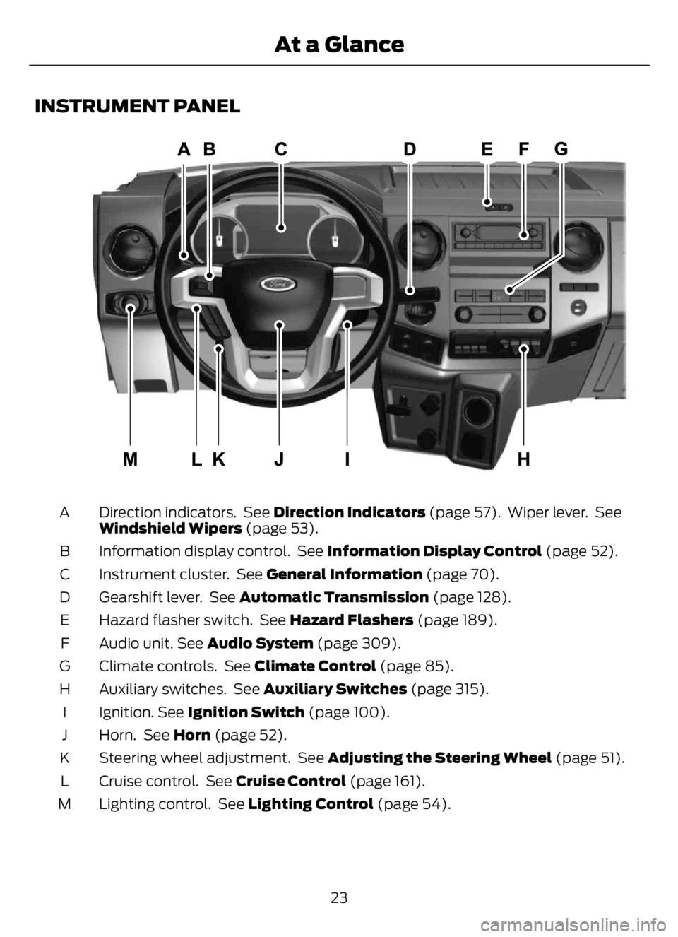
INSTRUMENT PANEL
E307565E307565
Direction indicators. See Direction Indicators (page 57). Wiper lever. See
Windshield Wipers (page 53). A
Information display control. See Information Display Control (page 52). B
Instrument cluster. See General Information (page 70). C
Gearshift lever. See Automatic Transmission (page 128). D
Hazard flasher switch. See Hazard Flashers (page 189). E
Audio unit. See Audio System (page 309). F
Climate controls. See Climate Control (page 85). G
Auxiliary switches. See Auxiliary Switches (page 315). H
Ignition. See Ignition Switch (page 100). I
Horn. See Horn (page 52). J
Steering wheel adjustment. See Adjusting the Steering Wheel (page 51). K
Cruise control. See Cruise Control (page 161). L
Lighting control. See Lighting Control (page 54). M
23
At a Glance
Page 64 of 378
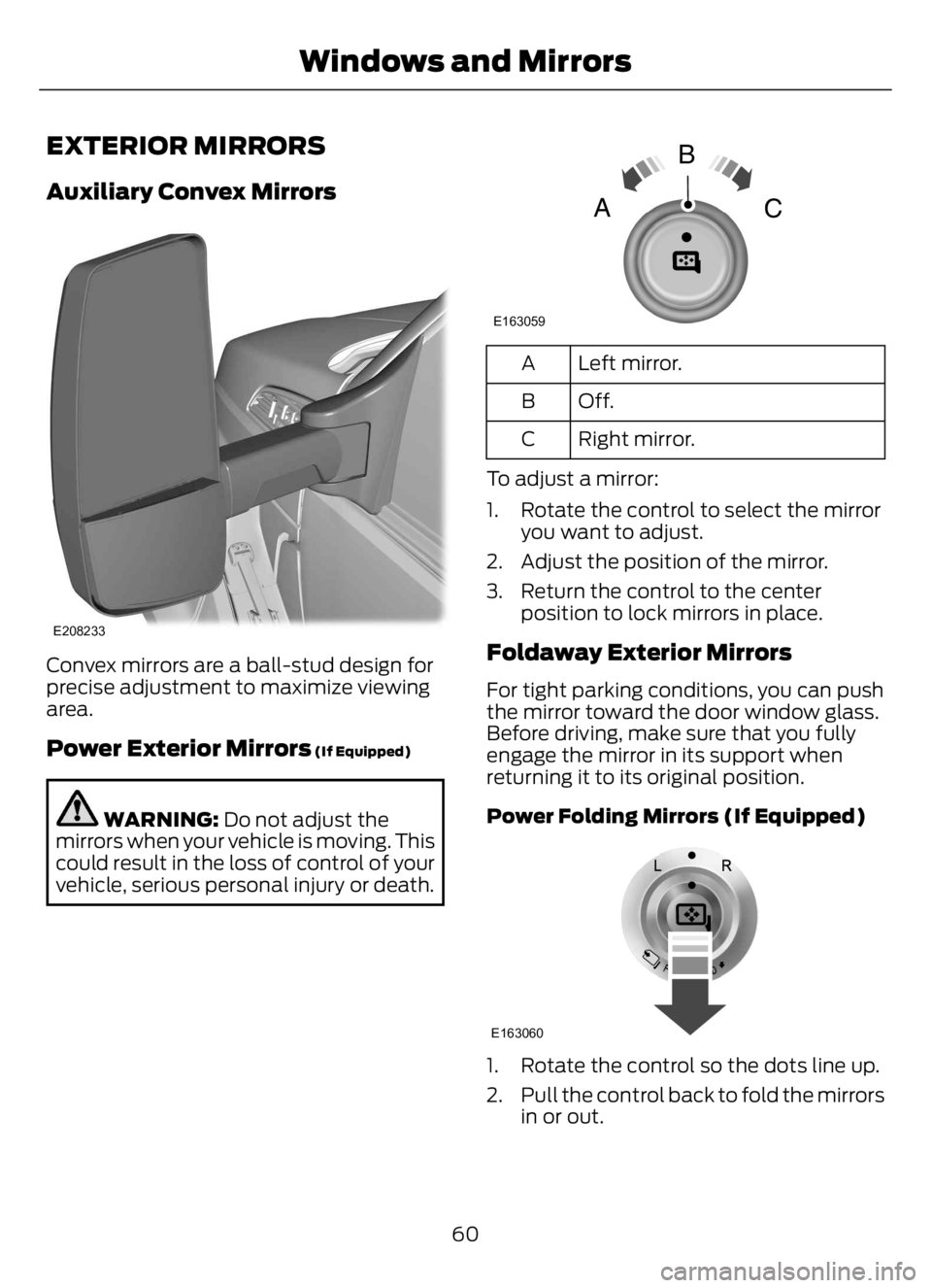
EXTERIOR MIRRORS
Auxiliary Convex Mirrors
E208233
Convex mirrors are a ball-stud design for
precise adjustment to maximize viewing
area.
Power Exterior Mirrors (If Equipped)
WARNING: Do not adjust the
mirrors when your vehicle is moving. This
could result in the loss of control of your
vehicle, serious personal injury or death.
E163059
B
AC
Left mirror. A
Off. B
Right mirror. C
To adjust a mirror:
1. Rotate the control to select the mirror
you want to adjust.
2. Adjust the position of the mirror.
3. Return the control to the center
position to lock mirrors in place.
Foldaway Exterior Mirrors
For tight parking conditions, you can push
the mirror toward the door window glass.
Before driving, make sure that you fully
engage the mirror in its support when
returning it to its original position.
Power Folding Mirrors (If Equipped)
E163060
1. Rotate the control so the dots line up.
2. Pull the control back to fold the mirrors
in or out.
60
Windows and Mirrors
Page 99 of 378
12 Volt DC Power Point
WARNING: Do not plug optional
electrical accessories into the cigar
lighter socket. Incorrect use of the cigar
lighter can cause damage not covered
by the vehicle warranty, and can result
in fire or serious injury.
Note:When you switch the ignition on, you
can use the socket to power 12 volt
appliances with a maximum current rating
of 15 amps.
If the power supply does not work after you
switch the ignition off, switch the ignition
on.
Note:Do not hang any accessory from the
accessory plug.
Note:Do not use the power point over the
vehicle capacity of 12 volt DC 180 watts or
a fuse may blow.
Note:Always keep the power point caps
closed when not in use.
Do not insert objects other than an
accessory plug into the power point. This
damages the power point and may blow
the fuse.
Run the vehicle for full capacity use of the
power point.
To prevent the battery from running out of
charge:
• Do not use the power point longer than
necessary when the vehicle is not
running.
• Do not leave devices plugged in
overnight or when you park your vehicle
for extended periods.
Locations
Power points may be in the following
locations:
• On the instrument panel (two
locations).
• Inside the front under-seat storage
compartment.
• Inside the rear under-seat storage
compartment.
110 Volt AC Power Point (If Equipped)
WARNING: Do not keep electrical
devices plugged in the power point
whenever the device is not in use. Do not
use any extension cord with the 110 volt
AC power point, since it will defeat the
safety protection design. Doing so may
cause the power point to overload due
to powering multiple devices that can
reach beyond the 150 watt load limit and
could result in fire or serious injury.
Note:The power point turns off when you
switch the ignition off, or when the battery
voltage drops below 11 volts.
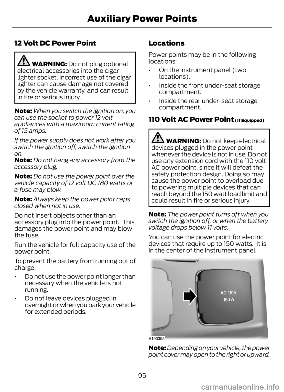
You can use the power point for electric
devices that require up to 150 watts. It is
in the center of the instrument panel.
E193395
Note:Depending on your vehicle, the power
point cover may open to the right or upward.
95
Auxiliary Power Points
Page 100 of 378
When the indicator light on the power point
is:
• On: The power point is working, the
ignition is on and a device is plugged
in.
• Off: The power point is off, the ignition
is off or no device is plugged in.
• Flashing: The power point is in fault
mode.
The power outlet temporarily turns off
power when in fault mode if the device
exceeds the 150 watt limit. Unplug your
device and switch the ignition off. Switch
the ignition back on, but do not plug your
device back in. Let the system cool off and
switch the ignition off to reset the fault
mode. Switch the ignition back on and
make sure the indicator light remains on.
Do not use the power point for certain
electric devices, including:
• Cathode-ray, tube-type televisions.
• Motor loads, such as vacuum cleaners,
electric saws and other electric power
tools or compressor-driven
refrigerators.
• Measuring devices, which process
precise data, such as medical
equipment or measuring equipment.
• Other appliances requiring an
extremely stable power supply such as
microcomputer-controlled electric
blankets or touch-sensor lamps.
96
Auxiliary Power Points
Page 137 of 378

Note:Do not rock your vehicle for more
than a minute or damage to the
transmission and tires could occur, or the
engine could overheat.
If your vehicle is stuck in mud or snow, you
could rock it out by shifting between
forward and reverse gears, stopping
between shifts in a steady pattern. Press
lightly on the accelerator in each gear.
POWER TAKE-OFF (IF EQUIPPED)
Auxiliary equipment called power take-off,
or PTO, is often added to the engine or
transmission to operate utility equipment.
Examples include a wheel-lift for tow
trucks, cranes, tools for construction or tire
service and pumping fluids. PTO
applications draw auxiliary horsepower
from the powertrain, often while the
vehicle is stationary or mobile. In the
stationary condition, there is limited
cooling air flow through the radiator and
around the vehicle that normally occurs
when a vehicle is moving. The aftermarket
PTO system installer, having the most
knowledge of the final application, is
responsible for determining whether
additional chassis heat protection or
powertrain cooling is required and alerting
the user to the safe and proper operation.
Your vehicle is approved for use as a
Stationary Mode, SplitShaft Mode or
Mobile Mode power source within the limits
and operating guidelines detailed in the
Ford Truck Body Builders Layout Book,
found at https://fordbbas.com/home and
through the Ford Truck Body Builders
Advisory Service. The transmission power
source modes are engine specific.
133
Transmission
Page 147 of 378
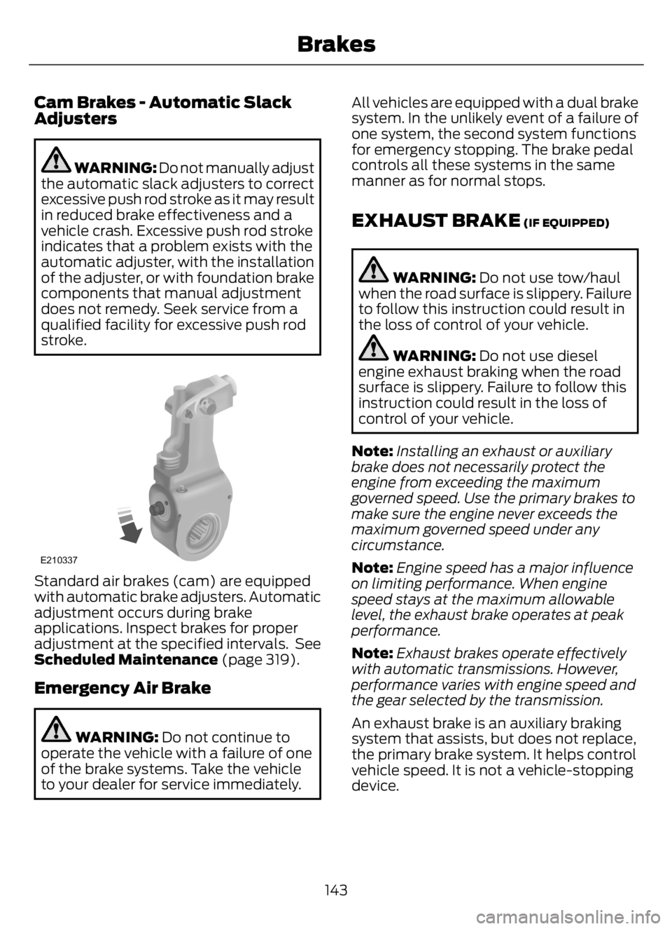
Cam Brakes - Automatic Slack
Adjusters
WARNING: Do not manually adjust
the automatic slack adjusters to correct
excessive push rod stroke as it may result
in reduced brake effectiveness and a
vehicle crash. Excessive push rod stroke
indicates that a problem exists with the
automatic adjuster, with the installation
of the adjuster, or with foundation brake
components that manual adjustment
does not remedy. Seek service from a
qualified facility for excessive push rod
stroke.
E210337
Standard air brakes (cam) are equipped
with automatic brake adjusters. Automatic
adjustment occurs during brake
applications. Inspect brakes for proper
adjustment at the specified intervals. See
Scheduled Maintenance (page 319).
Emergency Air Brake
WARNING: Do not continue to
operate the vehicle with a failure of one
of the brake systems. Take the vehicle
to your dealer for service immediately.All vehicles are equipped with a dual brake
system. In the unlikely event of a failure of
one system, the second system functions
for emergency stopping. The brake pedal
controls all these systems in the same
manner as for normal stops.
EXHAUST BRAKE (IF EQUIPPED)
WARNING: Do not use tow/haul
when the road surface is slippery. Failure
to follow this instruction could result in
the loss of control of your vehicle.
WARNING: Do not use diesel
engine exhaust braking when the road
surface is slippery. Failure to follow this
instruction could result in the loss of
control of your vehicle.
Note:Installing an exhaust or auxiliary
brake does not necessarily protect the
engine from exceeding the maximum
governed speed. Use the primary brakes to
make sure the engine never exceeds the
maximum governed speed under any
circumstance.
Note:Engine speed has a major influence
on limiting performance. When engine
speed stays at the maximum allowable
level, the exhaust brake operates at peak
performance.
Note:Exhaust brakes operate effectively
with automatic transmissions. However,
performance varies with engine speed and
the gear selected by the transmission.
An exhaust brake is an auxiliary braking
system that assists, but does not replace,
the primary brake system. It helps control
vehicle speed. It is not a vehicle-stopping
device.
143
Brakes
Page 317 of 378
Sorting by Categories
You can also sort and play music by
specific categories, for example artist or
album.
Press the OK button to view the available
categories.
AUDIO INPUT JACK (IF EQUIPPED)
WARNING: Driving while distracted
can result in loss of vehicle control, crash
and injury. We strongly recommend that
you use extreme caution when using any
device that may take your focus off the
road. Your primary responsibility is the
safe operation of your vehicle. We
recommend against the use of any
hand-held device while driving and
encourage the use of voice-operated
systems when possible. Make sure you
are aware of all applicable local laws
that may affect the use of electronic
devices while driving.
WARNING: Always place your
device in a secure location in your vehicle
so it does not become a projectile in a
sudden stop or crash. Failure to follow
this instruction could result in personal
injury.
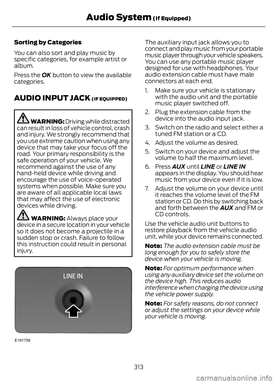
E191758
The auxiliary input jack allows you to
connect and play music from your portable
music player through your vehicle speakers.
You can use any portable music player
designed for use with headphones. Your
audio extension cable must have male
connectors at each end.
1. Make sure your vehicle is stationary
with the audio unit and the portable
music player switched off.
2. Plug the extension cable from the
device into the audio input jack.
3. Switch on the radio and select either a
tuned FM station or a CD.
4. Adjust the volume as desired.
5. Switch on your device and adjust the
volume to half the maximum level.
6. Press AUX until LINE or LINE IN
appears in the display. You should hear
music from your device even if it is low.
7. Adjust the volume on your device until
it reaches the volume level of the FM
station or CD. Do this by switching back
and forth between the AUX and FM or
CD controls.
Use the vehicle audio unit buttons to
restore playback from the vehicle audio
unit, while your device remains connected.
Note:The audio extension cable must be
long enough for you to safely store the
device when your vehicle is moving.
Note:For optimum performance when
using any auxiliary device set the volume on
the device high. This reduces audio
interference when charging the device using
the vehicle power supply.
Note:For safety reasons, do not connect
or adjust the settings on your device while
your vehicle is moving.
313
Audio System (If Equipped)