relay FORD F650/750 2023 Owners Manual
[x] Cancel search | Manufacturer: FORD, Model Year: 2023, Model line: F650/750, Model: FORD F650/750 2023Pages: 378, PDF Size: 5.65 MB
Page 182 of 378
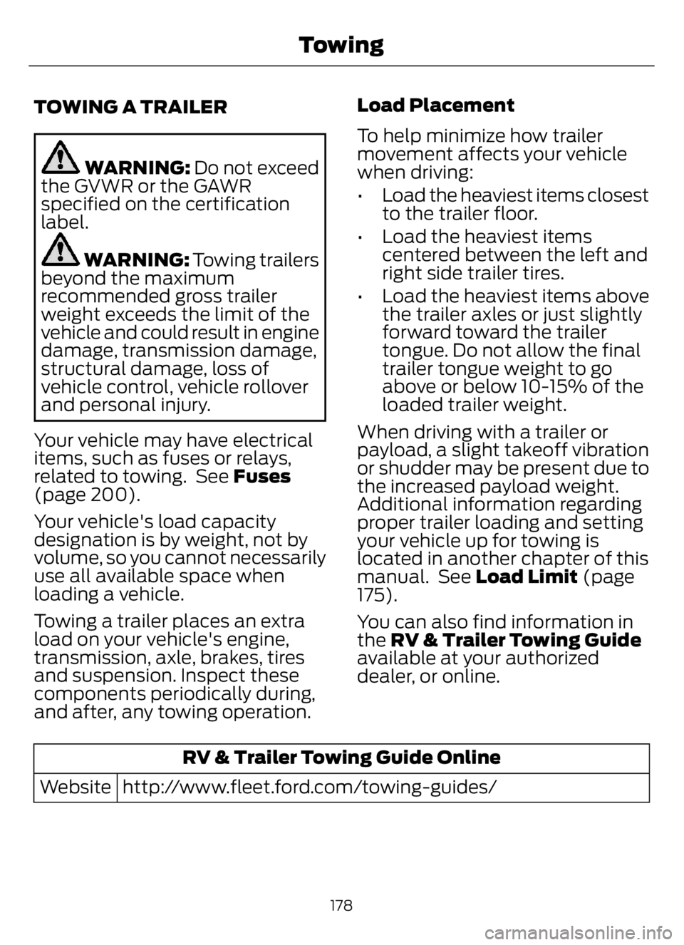
TOWING A TRAILER
WARNING: Do not exceed
the GVWR or the GAWR
specified on the certification
label.
WARNING: Towing trailers
beyond the maximum
recommended gross trailer
weight exceeds the limit of the
vehicle and could result in engine
damage, transmission damage,
structural damage, loss of
vehicle control, vehicle rollover
and personal injury.
Your vehicle may have electrical
items, such as fuses or relays,
related to towing. See Fuses
(page 200).
Your vehicle's load capacity
designation is by weight, not by
volume, so you cannot necessarily
use all available space when
loading a vehicle.
Towing a trailer places an extra
load on your vehicle's engine,
transmission, axle, brakes, tires
and suspension. Inspect these
components periodically during,
and after, any towing operation.Load Placement
To help minimize how trailer
movement affects your vehicle
when driving:
• Load the heaviest items closest
to the trailer floor.
• Load the heaviest items
centered between the left and
right side trailer tires.
• Load the heaviest items above
the trailer axles or just slightly
forward toward the trailer
tongue. Do not allow the final
trailer tongue weight to go
above or below 10-15% of the
loaded trailer weight.
When driving with a trailer or
payload, a slight takeoff vibration
or shudder may be present due to
the increased payload weight.
Additional information regarding
proper trailer loading and setting
your vehicle up for towing is
located in another chapter of this
manual. See Load Limit (page
175).
You can also find information in
the RV & Trailer Towing Guide
available at your authorized
dealer, or online.
RV & Trailer Towing Guide Online
http://www.fleet.ford.com/towing-guides/ Website
178
Towing
Page 205 of 378
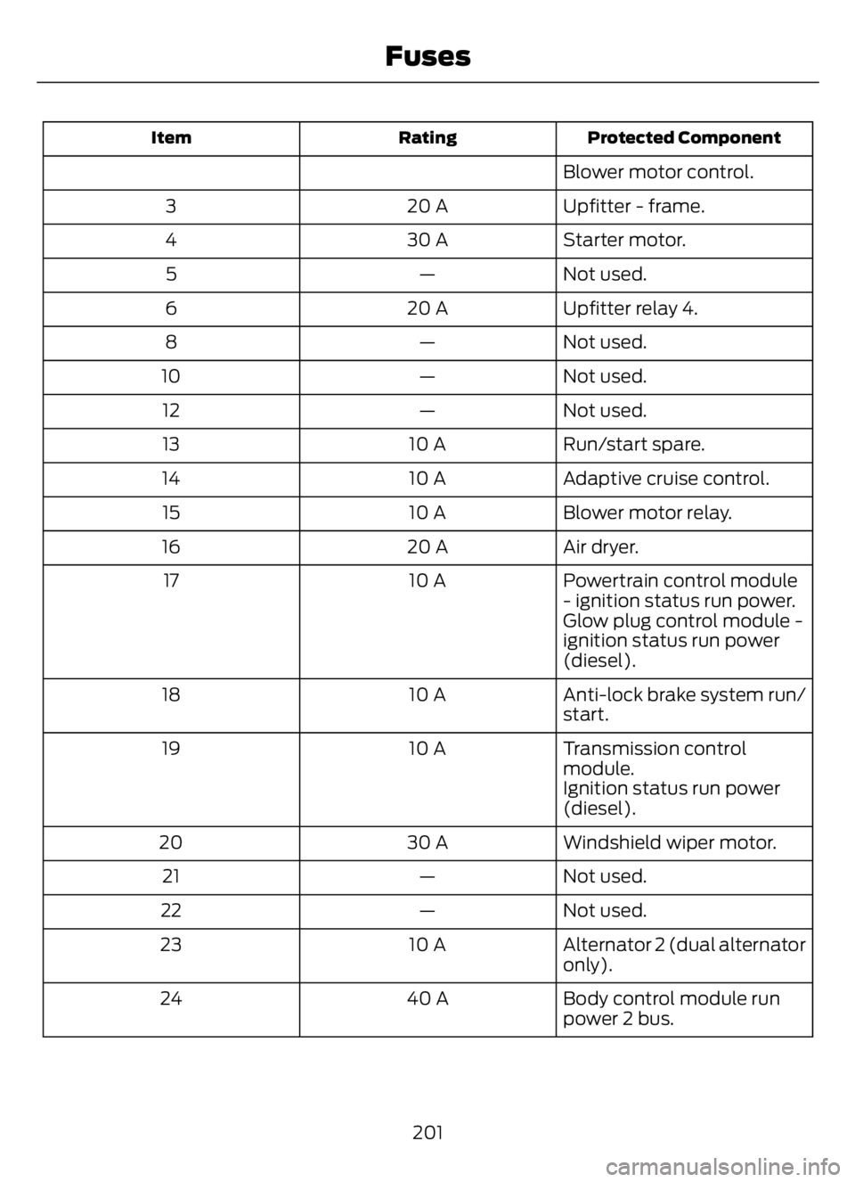
Protected Component Rating Item
Blower motor control.
Upfitter - frame. 20 A 3
Starter motor. 30 A 4
Not used. — 5
Upfitter relay 4. 20 A 6
Not used. — 8
Not used. — 10
Not used. — 12
Run/start spare. 10 A 13
Adaptive cruise control. 10 A 14
Blower motor relay. 10 A 15
Air dryer. 20 A 16
Powertrain control module
- ignition status run power. 10 A 17
Glow plug control module -
ignition status run power
(diesel).
Anti-lock brake system run/
start. 10 A 18
Transmission control
module. 10 A 19
Ignition status run power
(diesel).
Windshield wiper motor. 30 A 20
Not used. — 21
Not used. — 22
Alternator 2 (dual alternator
only). 10 A 23
Body control module run
power 2 bus. 40 A 24
201
Fuses
Page 206 of 378
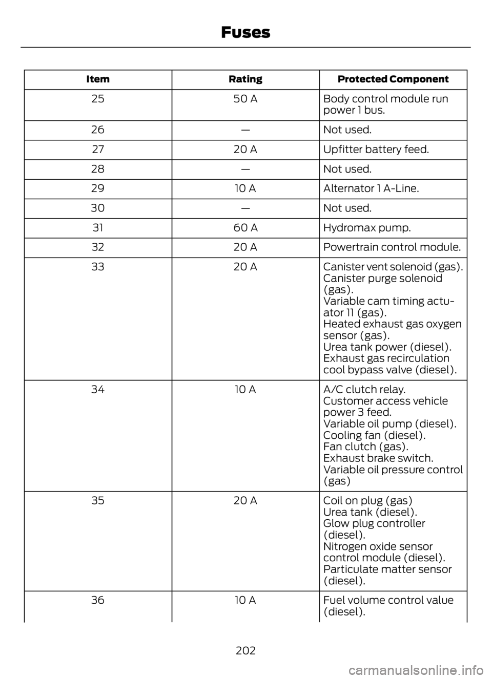
Protected Component Rating Item
Body control module run
power 1 bus. 50 A 25
Not used. — 26
Upfitter battery feed. 20 A 27
Not used. — 28
Alternator 1 A-Line. 10 A 29
Not used. — 30
Hydromax pump. 60 A 31
Powertrain control module. 20 A 32
Canister vent solenoid (gas). 20 A 33
Canister purge solenoid
(gas).
Variable cam timing actu-
ator 11 (gas).
Heated exhaust gas oxygen
sensor (gas).
Urea tank power (diesel).
Exhaust gas recirculation
cool bypass valve (diesel).
A/C clutch relay. 10 A 34
Customer access vehicle
power 3 feed.
Variable oil pump (diesel).
Cooling fan (diesel).
Fan clutch (gas).
Exhaust brake switch.
Variable oil pressure control
(gas)
Coil on plug (gas) 20 A 35
Urea tank (diesel).
Glow plug controller
(diesel).
Nitrogen oxide sensor
control module (diesel).
Particulate matter sensor
(diesel).
Fuel volume control value
(diesel). 10 A 36
202
Fuses
Page 207 of 378
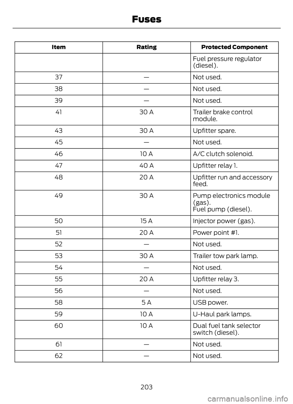
Protected Component Rating Item
Fuel pressure regulator
(diesel).
Not used. — 37
Not used. — 38
Not used. — 39
Trailer brake control
module. 30 A 41
Upfitter spare. 30 A 43
Not used. — 45
A/C clutch solenoid. 10 A 46
Upfitter relay 1. 40 A 47
Upfitter run and accessory
feed. 20 A 48
Pump electronics module
(gas). 30 A 49
Fuel pump (diesel).
Injector power (gas). 15 A 50
Power point #1. 20 A 51
Not used. — 52
Trailer tow park lamp. 30 A 53
Not used. — 54
Upfitter relay 3. 20 A 55
Not used. — 56
USB power. 5 A 58
U-Haul park lamps. 10 A 59
Dual fuel tank selector
switch (diesel). 10 A 60
Not used. — 61
Not used. — 62
203
Fuses
Page 208 of 378
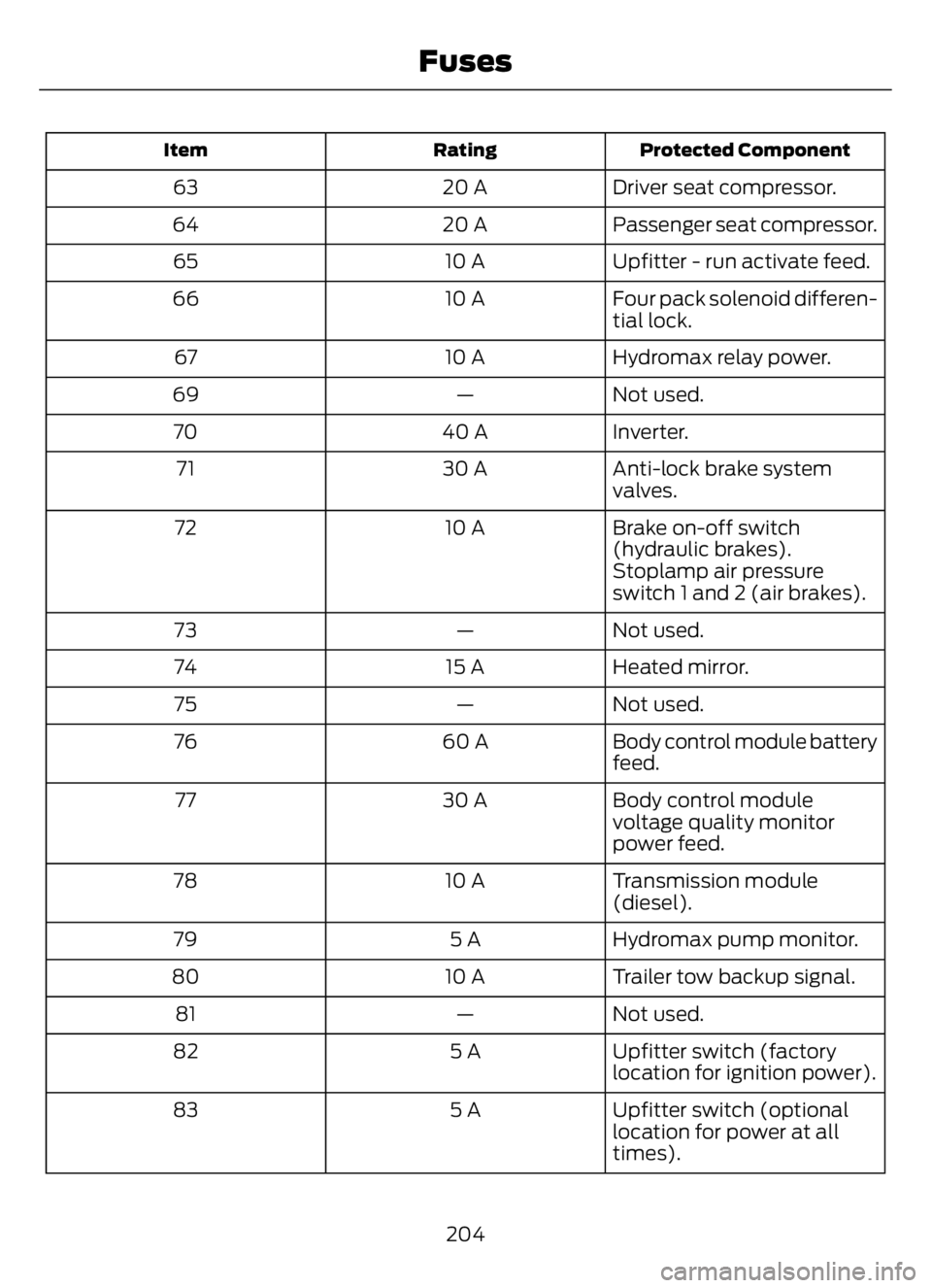
Protected Component Rating Item
Driver seat compressor. 20 A 63
Passenger seat compressor. 20 A 64
Upfitter - run activate feed. 10 A 65
Four pack solenoid differen-
tial lock. 10 A 66
Hydromax relay power. 10 A 67
Not used. — 69
Inverter. 40 A 70
Anti-lock brake system
valves. 30 A 71
Brake on-off switch
(hydraulic brakes). 10 A 72
Stoplamp air pressure
switch 1 and 2 (air brakes).
Not used. — 73
Heated mirror. 15 A 74
Not used. — 75
Body control module battery
feed. 60 A 76
Body control module
voltage quality monitor
power feed. 30 A 77
Transmission module
(diesel). 10 A 78
Hydromax pump monitor. 5 A 79
Trailer tow backup signal. 10 A 80
Not used. — 81
Upfitter switch (factory
location for ignition power). 5 A 82
Upfitter switch (optional
location for power at all
times). 5 A 83
204
Fuses
Page 209 of 378
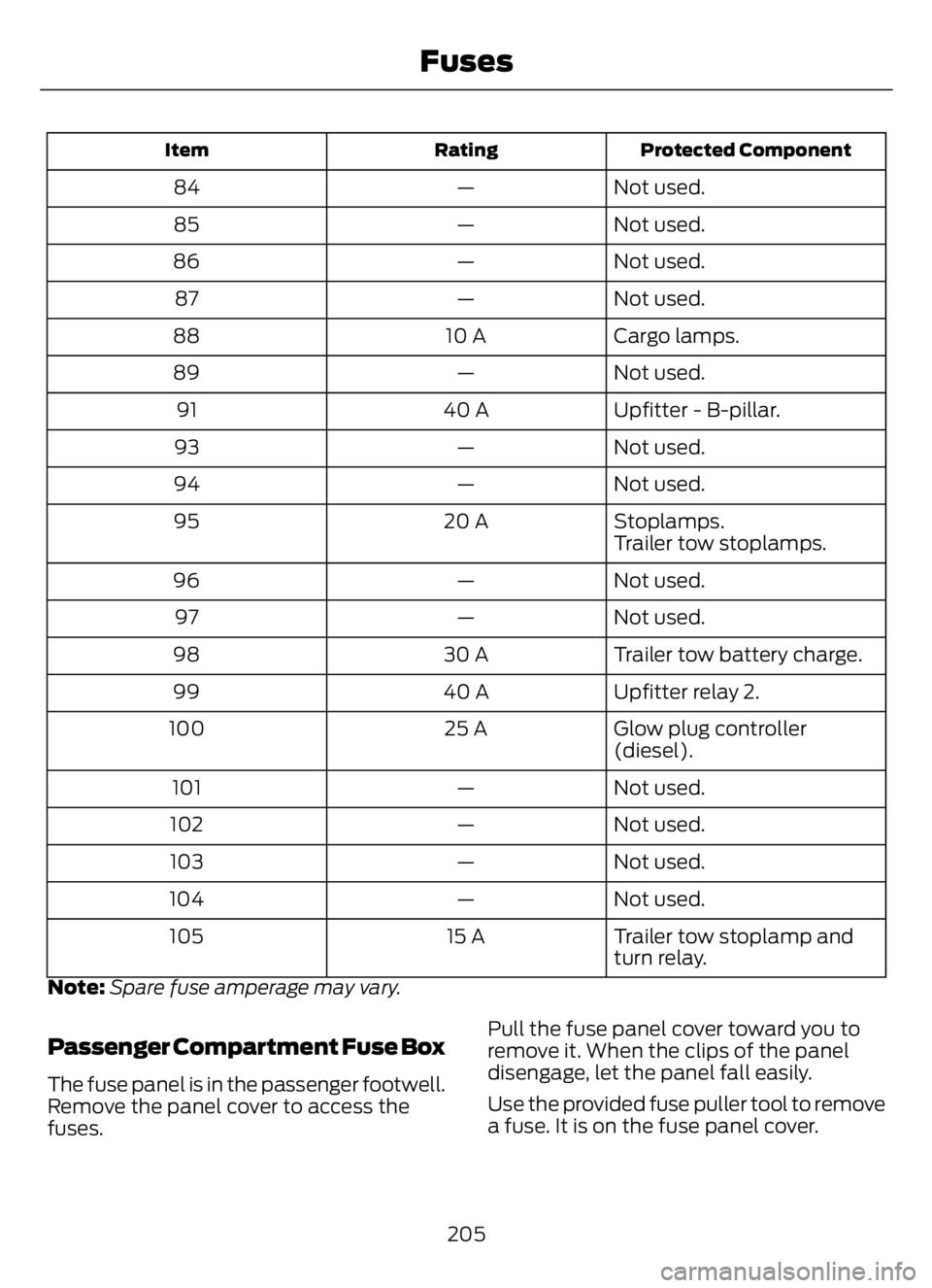
Protected Component Rating Item
Not used. — 84
Not used. — 85
Not used. — 86
Not used. — 87
Cargo lamps. 10 A 88
Not used. — 89
Upfitter - B-pillar. 40 A 91
Not used. — 93
Not used. — 94
Stoplamps. 20 A 95
Trailer tow stoplamps.
Not used. — 96
Not used. — 97
Trailer tow battery charge. 30 A 98
Upfitter relay 2. 40 A 99
Glow plug controller
(diesel). 25 A 100
Not used. — 101
Not used. — 102
Not used. — 103
Not used. — 104
Trailer tow stoplamp and
turn relay. 15 A 105
Note:Spare fuse amperage may vary.
Passenger Compartment Fuse Box
The fuse panel is in the passenger footwell.
Remove the panel cover to access the
fuses.Pull the fuse panel cover toward you to
remove it. When the clips of the panel
disengage, let the panel fall easily.
Use the provided fuse puller tool to remove
a fuse. It is on the fuse panel cover.
205
Fuses
Page 211 of 378
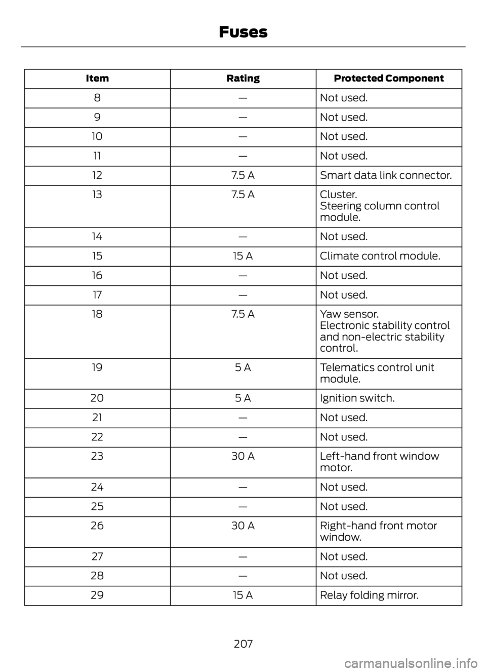
Protected Component Rating Item
Not used. — 8
Not used. — 9
Not used. — 10
Not used. — 11
Smart data link connector. 7.5 A 12
Cluster. 7.5 A 13
Steering column control
module.
Not used. — 14
Climate control module. 15 A 15
Not used. — 16
Not used. — 17
Yaw sensor. 7.5 A 18
Electronic stability control
and non-electric stability
control.
Telematics control unit
module. 5 A 19
Ignition switch. 5 A 20
Not used. — 21
Not used. — 22
Left-hand front window
motor. 30 A 23
Not used. — 24
Not used. — 25
Right-hand front motor
window. 30 A 26
Not used. — 27
Not used. — 28
Relay folding mirror. 15 A 29
207
Fuses
Page 212 of 378
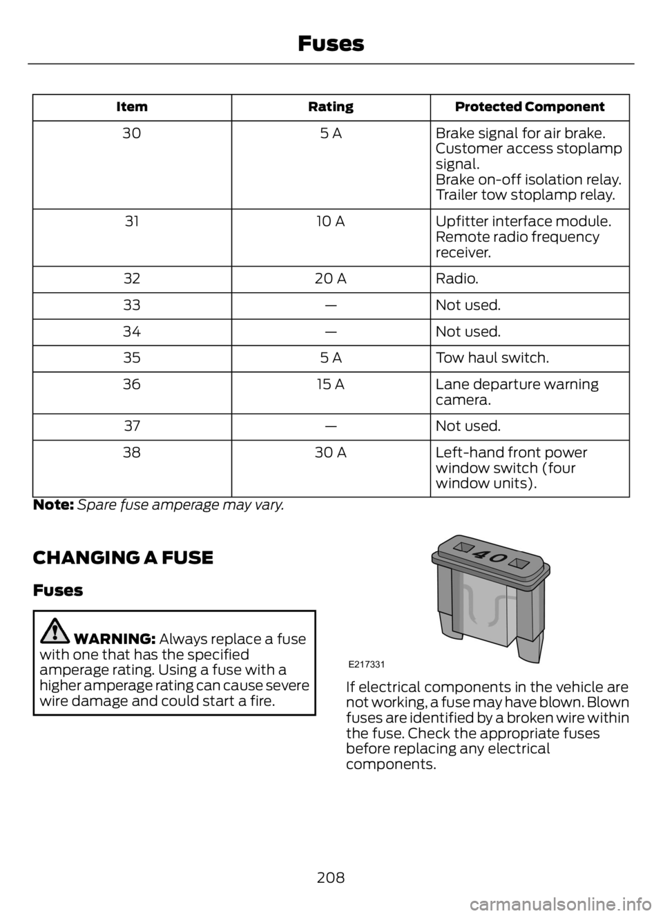
Protected Component Rating Item
Brake signal for air brake. 5 A 30
Customer access stoplamp
signal.
Brake on-off isolation relay.
Trailer tow stoplamp relay.
Upfitter interface module. 10 A 31
Remote radio frequency
receiver.
Radio. 20 A 32
Not used. — 33
Not used. — 34
Tow haul switch. 5 A 35
Lane departure warning
camera. 15 A 36
Not used. — 37
Left-hand front power
window switch (four
window units). 30 A 38
Note:Spare fuse amperage may vary.
CHANGING A FUSE
Fuses
WARNING: Always replace a fuse
with one that has the specified
amperage rating. Using a fuse with a
higher amperage rating can cause severe
wire damage and could start a fire.
E217331
If electrical components in the vehicle are
not working, a fuse may have blown. Blown
fuses are identified by a broken wire within
the fuse. Check the appropriate fuses
before replacing any electrical
components.
208
Fuses
Page 319 of 378

AUXILIARY SWITCHES (IF
EQUIPPED)
For maximum vehicle performance, keep
the following information in mind when
adding accessories or equipment to your
vehicle:
• When adding accessories, equipment,
passengers and luggage to your
vehicle, do not exceed the total weight
capacity of the vehicle or of the front
or rear axle (GVWR or GAWR as
indicated on the Safety Compliance
Certification label). Ask an authorized
dealer for specific weight information.
• The Federal Communications
Commission (FCC) and Canadian
Radio Telecommunications
Commission (CRTC) regulate the use
of mobile communications systems
equipped with radio transmitters, for
example, two-way radios, telephones
and theft alarms. Any such equipment
installed in your vehicle should comply
with Federal Communications
Commission (FCC) and Canadian
Radio Telecommunications
Commission (CRTC) regulations, and
should be installed by an authorized
dealer.
• An authorized dealer needs to install
mobile communications systems.
Improper installation may harm the
operation of your vehicle, particularly
if the manufacturer did not design the
mobile communication system
specifically for automotive use.
• If you or an authorized Ford dealer add
any non-Ford electrical or electronic
accessories or components to your
vehicle, you may adversely affect
battery performance and durability. In
addition, you may also adversely affect
the performance of other electrical
systems in the vehicle.
E163431
The auxiliary switch option package
provides four switches, mounted in the
center of the instrument panel. These
switches operate when the ignition is on
or from battery power, depending on the
switchable power distribution box fuse
locations #82 and #83. We recommend,
however, that the engine remain running
to maintain battery charge when using the
auxiliary switches for extended periods of
time or higher current draws.
Note:When your vehicle has a diesel
engine, use the auxiliary switches only while
the engine is running. The glow plugs also
drain battery power when the ignition key is
in the on position. Using the auxiliary
switches, even for limited amounts of time,
can cause your battery to drain quickly and
prevent your vehicle from restarting.
When switched on, the auxiliary switches
provide 20 amps or 40 amps of electrical
battery power for a variety of personal or
commercial uses.
The relays for the auxiliary switches are in
the power distribution box under the hood
by the right-hand fender. See your
authorized dealer for service.
Each switch includes a power lead, a
blunt-cut and sealed wire below the
instrument panel and to the left of the
steering column in the driver footwell area.
The power leads are coded as shown:
315
Accessories
Page 320 of 378
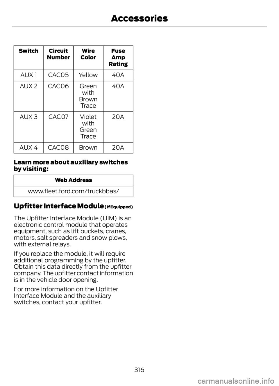
Fuse
Amp
Rating Wire
Color Circuit
Number Switch
40A Yellow CAC05 AUX 1
40A Green
with
Brown
Tr a c e CAC06 AUX 2
20A Violet
with
Green
Tr a c e CAC07 AUX 3
20A Brown CAC08 AUX 4
Learn more about auxiliary switches
by visiting:
Web Address
www.fleet.ford.com/truckbbas/
Upfitter Interface Module (If Equipped)
The Upfitter Interface Module (UIM) is an
electronic control module that operates
equipment, such as lift buckets, cranes,
motors, salt spreaders and snow plows,
with external relays.
If you replace the module, it will require
additional programming by the upfitter.
Obtain this data directly from the upfitter
company. The upfitter contact information
is in the vehicle door opening.
For more information on the Upfitter
Interface Module and the auxiliary
switches, contact your upfitter.
316
Accessories