key FORD F650/750 2024 Owner's Manual
[x] Cancel search | Manufacturer: FORD, Model Year: 2024, Model line: F650/750, Model: FORD F650/750 2024Pages: 386, PDF Size: 8.7 MB
Page 170 of 386
DRIVER ALERT (IF EQUIPPED)
WARNING: You are responsible forcontrolling your vehicle at all times. Thesystem is designed to be an aid and doesnot relieve you of your responsibility todrive with due care and attention. Failureto follow this instruction could result inthe loss of control of your vehicle,personal injury or death.
WARNING: The system may notfunction if the sensor is blocked.
WARNING: Take regular restbreaks if you feel tired. Do not wait forthe system to warn you.
WARNING: Certain driving stylesmay result in the system warning youeven if you are not feeling tired.
WARNING: In cold and severeweather conditions the system may notfunction. Rain, snow and spray can alllimit sensor performance.
WARNING: The system will notoperate if the sensor cannot track theroad lane markings.
WARNING: If damage occurs in theimmediate area surrounding the sensor,have your vehicle checked as soon aspossible.
WARNING: The system may notcorrectly operate if your vehicle is fittedwith a suspension kit not approved byus.
Note:Keep the windshield free fromobstructions. For example, bird droppings,insects and snow or ice.
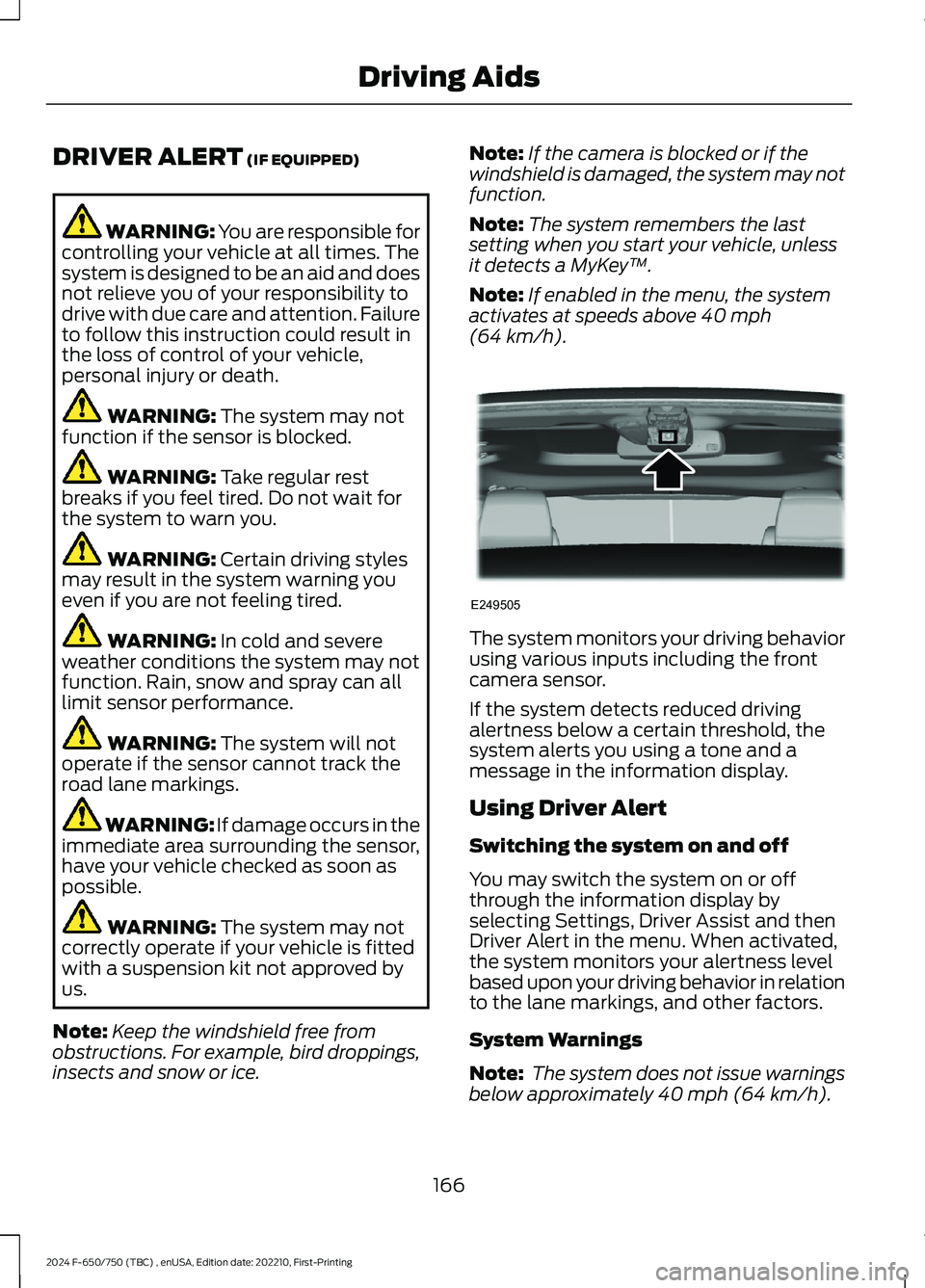
Note:If the camera is blocked or if thewindshield is damaged, the system may notfunction.
Note:The system remembers the lastsetting when you start your vehicle, unlessit detects a MyKey™.
Note:If enabled in the menu, the systemactivates at speeds above 40 mph(64 km/h).
The system monitors your driving behaviorusing various inputs including the frontcamera sensor.
If the system detects reduced drivingalertness below a certain threshold, thesystem alerts you using a tone and amessage in the information display.
Using Driver Alert
Switching the system on and off
You may switch the system on or offthrough the information display byselecting Settings, Driver Assist and thenDriver Alert in the menu. When activated,the system monitors your alertness levelbased upon your driving behavior in relationto the lane markings, and other factors.
System Warnings
Note: The system does not issue warningsbelow approximately 40 mph (64 km/h).
166
2024 F-650/750 (TBC) , enUSA, Edition date: 202210, First-PrintingDriving AidsE249505
Page 176 of 386
Pre-Collision Assist Settings
Active braking turns on every time youswitch the ignition on. You cannot adjustthe Pre-Collision Assist settings.
Note:We recommend that you switch thesystem off if you install a snow plow orsimilar object in such a way that it mayblock the radar sensor. Your vehicleremembers the system status across keycycles.
Blocked Sensors
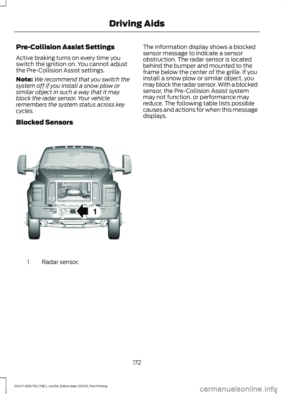
Radar sensor.1
The information display shows a blockedsensor message to indicate a sensorobstruction. The radar sensor is locatedbehind the bumper and mounted to theframe below the center of the grille. If youinstall a snow plow or similar object, youmay block the radar sensor. With a blockedsensor, the Pre-Collision Assist systemmay not function, or performance mayreduce. The following table lists possiblecauses and actions for when this messagedisplays.
172
2024 F-650/750 (TBC) , enUSA, Edition date: 202210, First-PrintingDriving AidsE312316
Page 180 of 386
Note:Switch the system off if you install asnowplow or similar object in such a waythat it may block the radar sensor. Yourvehicle remembers the selected settingacross key cycles.
Blocked Sensors
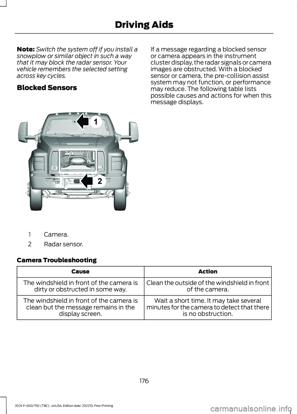
Camera.1
Radar sensor.2
If a message regarding a blocked sensoror camera appears in the instrumentcluster display, the radar signals or cameraimages are obstructed. With a blockedsensor or camera, the pre-collision assistsystem may not function, or performancemay reduce. The following table listspossible causes and actions for when thismessage displays.
Camera Troubleshooting
ActionCause
Clean the outside of the windshield in frontof the camera.The windshield in front of the camera isdirty or obstructed in some way.
Wait a short time. It may take severalminutes for the camera to detect that thereis no obstruction.
The windshield in front of the camera isclean but the message remains in thedisplay screen.
176
2024 F-650/750 (TBC) , enUSA, Edition date: 202210, First-PrintingDriving AidsE311873
Page 190 of 386

GENERAL DRIVING POINTS
General Information
•Accelerate smoothly and evenly. Rapidacceleration increases fuelconsumption without increasing engineperformance.
•When approaching a hill, press theaccelerator smoothly to start theincline at full power, and then shiftdown as needed to maintain vehiclespeed.
•When going down a hill, or long steepgrades, prevent overspeeding of theengine. Normally, choose the samegear to descend the hill that you use toascend the hill. The engine governorhas no control over engine speed whenit is being pushed by a loaded vehicle.
•Do not operate in a gear that permitsan engine speed more than themaximum governed speed or high-idleRPM (no load).
•Always shift to a lower gear at highaltitudes to prevent engine smoking.
Backing Up
WARNING: All vehicles have blindspots. To reduce the risk of severe injuryor property damage, never move yourvehicle to the side or rear or change laneswithout being sure your way is clear onboth sides and to your rear.
WARNING: To reduce the risk ofthe possibility of personal injury whilebacking up the vehicle, always be sureyour vehicle’s path is clear.
Before backing up your vehicle, be sure youcan do so safely. If anything behind the cablimits your view, do not rely on mirrorsalone to make sure that your intended pathis clear. If other people are in the vicinity,have someone standing well behind yourvehicle and outside of your intended path(visible through an exterior mirror) guideyou as you back up.
Although OSHA or some governmentalregulations may require the use of anelectrical or mechanical back up alarm towarn bystanders, such an alarm does notguarantee that the intended path is clear.When in doubt, get out of your vehicle andvisually check the intended path is clear.Back up slowly as to allow others time tomove, if necessary.
If you install an electrical back up alarm,connect it to the backup lamp circuit.
Parking
WARNING: When parking yourvehicle, do not leave the transmission ingear; if the key is in the on position andthe vehicle rolls, the engine could start.Failure to follow these instructions couldresult in an unattended vehicle moving,possibly causing personal injury orproperty damage.
Always use the parking brake. Whenparking on a grade, block the wheels andturn the front wheels to one side so that ifyour vehicle rolls, the front tires act againstthe curb to stop your vehicle. The frontwheels are more effective at stopping arolling vehicle than the rear wheels.
186
2024 F-650/750 (TBC) , enUSA, Edition date: 202210, First-PrintingDriving Hints
Page 198 of 386
ROADSIDE ASSISTANCE
Vehicles Sold in the United States:Getting Roadside Assistance
If you have a vehicle concern, Ford MotorCompany offers a complimentary roadsideassistance program. This program isseparate from the New Vehicle LimitedWarranty.
The service is available:
•24 hours a day, seven days a week.
•For the coverage period supplied withyour vehicle.
Knowing your vehicle's VIN, mileage andyour specific location allows help to get toyou faster.
Roadside Assistance covers:
•A flat tire change with a good spare(except vehicles supplied with a tireinflation kit).
•Battery jump start.
•Lock-out assistance (key replacementcost is the customer's responsibility).
•Fuel delivery — independent servicecontractors, if not prohibited by state,local or municipal law, shall deliver upto 2 gal (8 L) of gasoline or 5 gal (20 L)of diesel fuel to a disabled vehicle.Roadside assistance limits fuel deliveryservice to two no-charge occurrenceswithin a 12-month period.
•Winch out — available within 100 ft(30 m) of a paved or countymaintained road, no recoveries.
•Towing — independent servicecontractors, if not prohibited by state,local or municipal law, shall tow Fordeligible vehicles to an authorized dealerwithin 50 mi (80 km) of thedisablement location or to the nearestauthorized dealer. If a memberrequests a tow to an authorized dealerthat is more than 50 mi (80 km) fromthe disablement location, the membershall be responsible for any mileagecosts in excess of 50 mi (80 km).Warranty towing, non-warranty towingand collision towing are available.
•Roadside Assistance includes up to$200 for a towed trailer if the disabledeligible vehicle requires service at thenearest authorized dealer. If the towingvehicle is operational but the trailer isnot, then the trailer does not qualify forany roadside services.
Vehicles Sold in the United States:Using Roadside Assistance
United States vehicle customers whorequire Roadside Assistance, call1-800-241-3673.
If you need to arrange roadside assistanceon your own, Ford Motor Companyreimburses a reasonable amount fortowing to the nearest dealership within50 mi (80 km). To obtain reimbursementinformation, United States vehiclecustomers call 1-800-241-3673.Customers need to submit their originalreceipts.
Vehicles Sold in Canada: GettingRoadside Assistance
If you have a vehicle concern, Ford MotorCompany of Canada, Limited offers acomplimentary roadside assistanceprogram. This program is eligible withinCanada or the continental United States.
The service is available 24 hours a day,seven days a week.
194
2024 F-650/750 (TBC) , enUSA, Edition date: 202210, First-PrintingCrash and Breakdown Information
Page 218 of 386
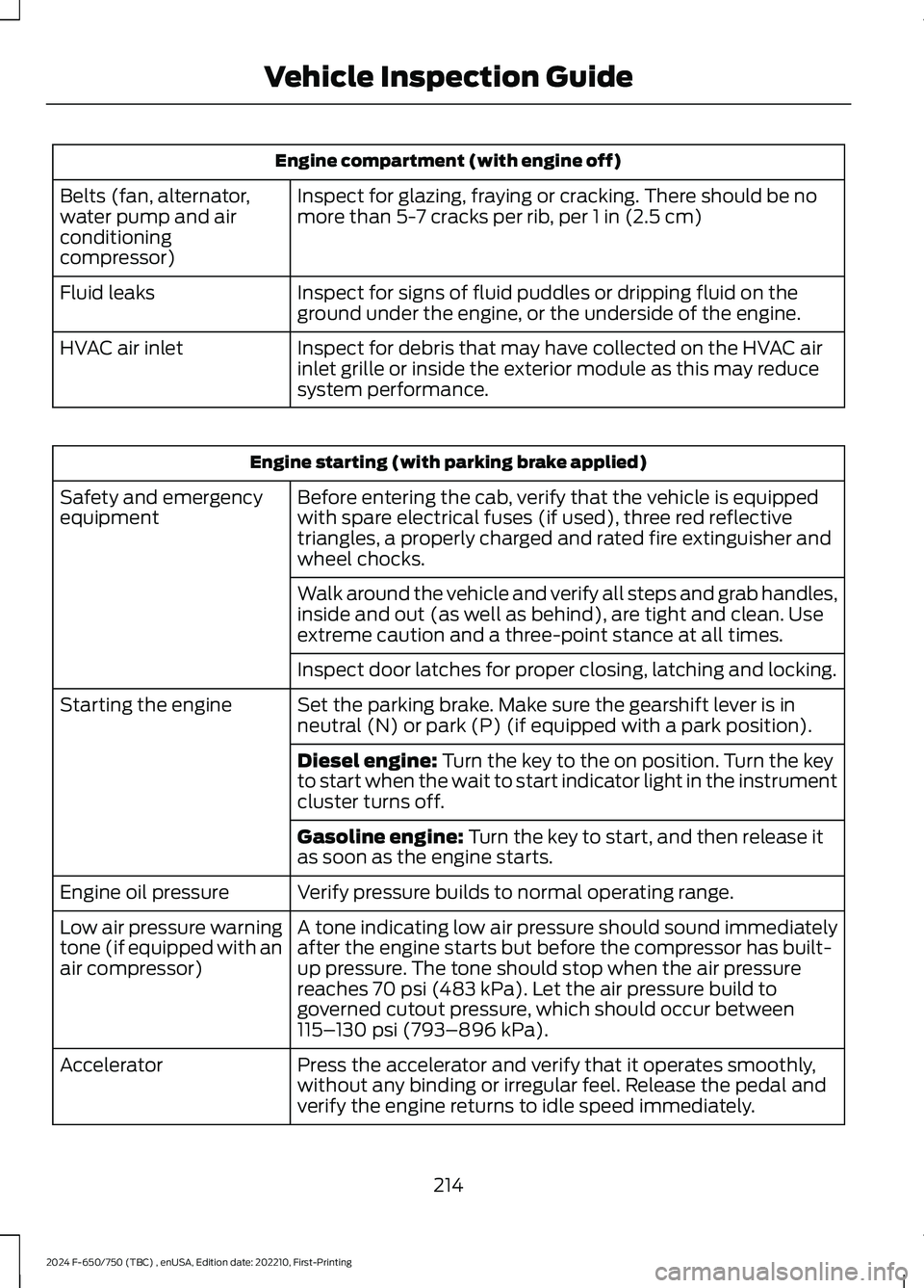
Engine compartment (with engine off)
Inspect for glazing, fraying or cracking. There should be nomore than 5-7 cracks per rib, per 1 in (2.5 cm)Belts (fan, alternator,water pump and airconditioningcompressor)
Inspect for signs of fluid puddles or dripping fluid on theground under the engine, or the underside of the engine.Fluid leaks
Inspect for debris that may have collected on the HVAC airinlet grille or inside the exterior module as this may reducesystem performance.
HVAC air inlet
Engine starting (with parking brake applied)
Before entering the cab, verify that the vehicle is equippedwith spare electrical fuses (if used), three red reflectivetriangles, a properly charged and rated fire extinguisher andwheel chocks.
Safety and emergencyequipment
Walk around the vehicle and verify all steps and grab handles,inside and out (as well as behind), are tight and clean. Useextreme caution and a three-point stance at all times.
Inspect door latches for proper closing, latching and locking.
Set the parking brake. Make sure the gearshift lever is inneutral (N) or park (P) (if equipped with a park position).Starting the engine
Diesel engine: Turn the key to the on position. Turn the keyto start when the wait to start indicator light in the instrumentcluster turns off.
Gasoline engine: Turn the key to start, and then release itas soon as the engine starts.
Verify pressure builds to normal operating range.Engine oil pressure
A tone indicating low air pressure should sound immediatelyafter the engine starts but before the compressor has built-up pressure. The tone should stop when the air pressurereaches 70 psi (483 kPa). Let the air pressure build togoverned cutout pressure, which should occur between115–130 psi (793–896 kPa).
Low air pressure warningtone (if equipped with anair compressor)
Press the accelerator and verify that it operates smoothly,without any binding or irregular feel. Release the pedal andverify the engine returns to idle speed immediately.
Accelerator
214
2024 F-650/750 (TBC) , enUSA, Edition date: 202210, First-PrintingVehicle Inspection Guide
Page 219 of 386
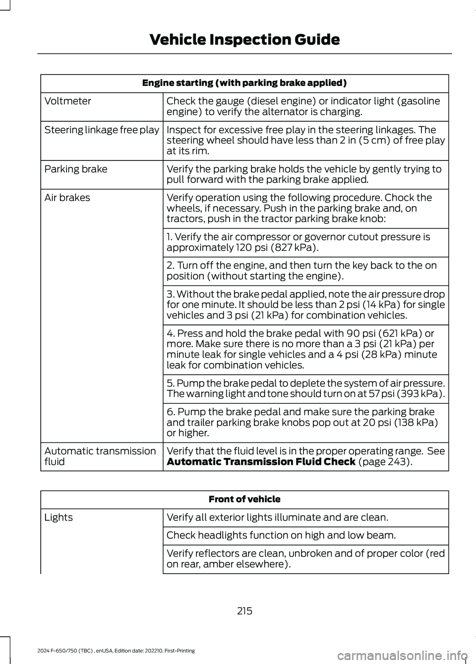
Engine starting (with parking brake applied)
Check the gauge (diesel engine) or indicator light (gasolineengine) to verify the alternator is charging.Voltmeter
Inspect for excessive free play in the steering linkages. Thesteering wheel should have less than 2 in (5 cm) of free playat its rim.
Steering linkage free play
Verify the parking brake holds the vehicle by gently trying topull forward with the parking brake applied.Parking brake
Verify operation using the following procedure. Chock thewheels, if necessary. Push in the parking brake and, ontractors, push in the tractor parking brake knob:
Air brakes
1. Verify the air compressor or governor cutout pressure isapproximately 120 psi (827 kPa).
2. Turn off the engine, and then turn the key back to the onposition (without starting the engine).
3. Without the brake pedal applied, note the air pressure dropfor one minute. It should be less than 2 psi (14 kPa) for singlevehicles and 3 psi (21 kPa) for combination vehicles.
4. Press and hold the brake pedal with 90 psi (621 kPa) ormore. Make sure there is no more than a 3 psi (21 kPa) perminute leak for single vehicles and a 4 psi (28 kPa) minuteleak for combination vehicles.
5. Pump the brake pedal to deplete the system of air pressure.The warning light and tone should turn on at 57 psi (393 kPa).
6. Pump the brake pedal and make sure the parking brakeand trailer parking brake knobs pop out at 20 psi (138 kPa)or higher.
Verify that the fluid level is in the proper operating range. SeeAutomatic Transmission Fluid Check (page 243).Automatic transmissionfluid
Front of vehicle
Verify all exterior lights illuminate and are clean.Lights
Check headlights function on high and low beam.
Verify reflectors are clean, unbroken and of proper color (redon rear, amber elsewhere).
215
2024 F-650/750 (TBC) , enUSA, Edition date: 202210, First-PrintingVehicle Inspection Guide
Page 220 of 386
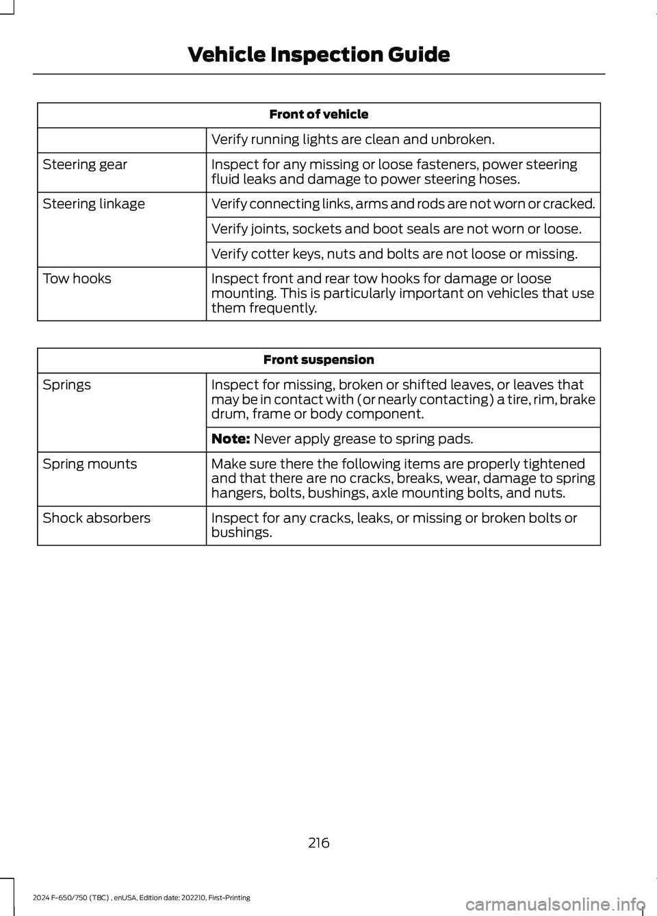
Front of vehicle
Verify running lights are clean and unbroken.
Inspect for any missing or loose fasteners, power steeringfluid leaks and damage to power steering hoses.Steering gear
Verify connecting links, arms and rods are not worn or cracked.Steering linkage
Verify joints, sockets and boot seals are not worn or loose.
Verify cotter keys, nuts and bolts are not loose or missing.
Inspect front and rear tow hooks for damage or loosemounting. This is particularly important on vehicles that usethem frequently.
Tow hooks
Front suspension
Inspect for missing, broken or shifted leaves, or leaves thatmay be in contact with (or nearly contacting) a tire, rim, brakedrum, frame or body component.
Springs
Note: Never apply grease to spring pads.
Make sure there the following items are properly tightenedand that there are no cracks, breaks, wear, damage to springhangers, bolts, bushings, axle mounting bolts, and nuts.
Spring mounts
Inspect for any cracks, leaks, or missing or broken bolts orbushings.Shock absorbers
216
2024 F-650/750 (TBC) , enUSA, Edition date: 202210, First-PrintingVehicle Inspection Guide
Page 252 of 386
the driver that battery protection actionsare active. These messages are only fornotification that an action is taking place,and not intended to indicate an electricalproblem or that the battery requiresreplacement.
Electrical accessory installation
To ensure proper operation of the BMS,any electrical devices that are added tothe vehicle should not have their groundconnection made directly at the negativebattery post. A connection at the negativebattery post can cause inaccuratemeasurements of the battery conditionand potential incorrect system operation.
Note:Electrical or electronic accessoriesadded to the vehicle by the dealer or theowner may adversely affect batteryperformance and durability, and may alsoaffect the performance of other electricalsystems in the vehicle.
When a battery replacement is required,the battery should only be replaced witha Ford recommended replacement batterywhich matches the electrical requirementsof the vehicle. After battery replacement,or in some cases after charging the batterywith the external charger, the BMS requireseight hours of vehicle sleep time (key offwith doors closed) to relearn the newbattery state of charge. Prior to relearningthe state of charge, the BMS may disableelectrical features (to protect the battery)earlier than normal.
ADJUSTING THE HEADLAMPS
Vertical Aim Adjustment
The headlamps on your vehicle areproperly aimed at the assembly plant. Ifyour vehicle has been in an accident, thealignment of your headlamps should bechecked by your authorized dealer.
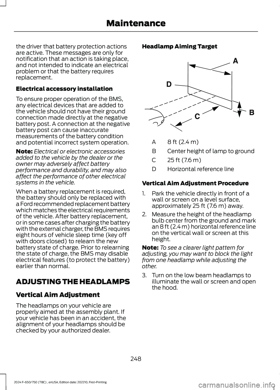
Headlamp Aiming Target
8 ft (2.4 m)A
Center height of lamp to groundB
25 ft (7.6 m)C
Horizontal reference lineD
Vertical Aim Adjustment Procedure
1.Park the vehicle directly in front of awall or screen on a level surface,approximately 25 ft (7.6 m) away.
2.Measure the height of the headlampbulb center from the ground and markan 8 ft (2.4 m) horizontal reference lineon the vertical wall or screen at thisheight.
Note:To see a clearer light pattern foradjusting, you may want to block the lightfrom one headlamp while adjusting theother.
3.Turn on the low beam headlamps toilluminate the wall or screen and openthe hood.
248
2024 F-650/750 (TBC) , enUSA, Edition date: 202210, First-PrintingMaintenanceE142592
Page 325 of 386
AUXILIARY SWITCHES (IF
EQUIPPED)
For maximum vehicle performance, keepthe following information in mind whenadding accessories or equipment to yourvehicle:
•When adding accessories, equipment,passengers and luggage to yourvehicle, do not exceed the total weightcapacity of the vehicle or of the frontor rear axle (GVWR or GAWR asindicated on the Safety ComplianceCertification label). Ask an authorizeddealer for specific weight information.
•The Federal CommunicationsCommission (FCC) and CanadianRadio TelecommunicationsCommission (CRTC) regulate the useof mobile communications systemsequipped with radio transmitters, forexample, two-way radios, telephonesand theft alarms. Any such equipmentinstalled in your vehicle should complywith Federal CommunicationsCommission (FCC) and CanadianRadio TelecommunicationsCommission (CRTC) regulations, andshould be installed by an authorizeddealer.
•An authorized dealer needs to installmobile communications systems.Improper installation may harm theoperation of your vehicle, particularlyif the manufacturer did not design themobile communication systemspecifically for automotive use.
•If you or an authorized Ford dealer addany non-Ford electrical or electronicaccessories or components to yourvehicle, you may adversely affectbattery performance and durability. Inaddition, you may also adversely affectthe performance of other electricalsystems in the vehicle.
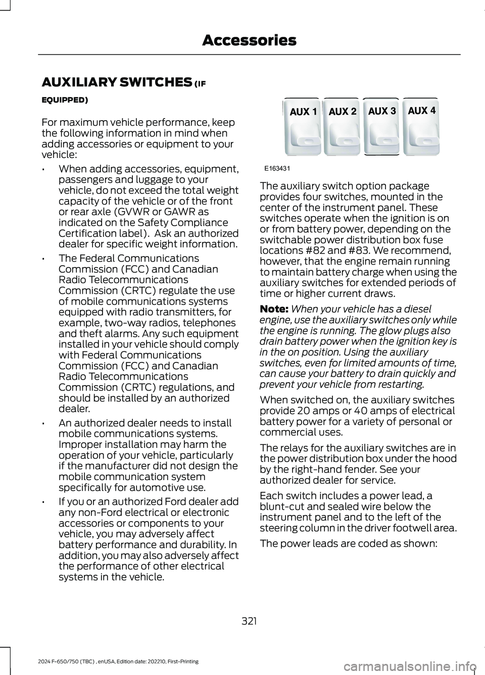
The auxiliary switch option packageprovides four switches, mounted in thecenter of the instrument panel. Theseswitches operate when the ignition is onor from battery power, depending on theswitchable power distribution box fuselocations #82 and #83. We recommend,however, that the engine remain runningto maintain battery charge when using theauxiliary switches for extended periods oftime or higher current draws.
Note:When your vehicle has a dieselengine, use the auxiliary switches only whilethe engine is running. The glow plugs alsodrain battery power when the ignition key isin the on position. Using the auxiliaryswitches, even for limited amounts of time,can cause your battery to drain quickly andprevent your vehicle from restarting.
When switched on, the auxiliary switchesprovide 20 amps or 40 amps of electricalbattery power for a variety of personal orcommercial uses.
The relays for the auxiliary switches are inthe power distribution box under the hoodby the right-hand fender. See yourauthorized dealer for service.
Each switch includes a power lead, ablunt-cut and sealed wire below theinstrument panel and to the left of thesteering column in the driver footwell area.
The power leads are coded as shown:
321
2024 F-650/750 (TBC) , enUSA, Edition date: 202210, First-PrintingAccessoriesE163431