relay FORD F650/750 2024 Owners Manual
[x] Cancel search | Manufacturer: FORD, Model Year: 2024, Model line: F650/750, Model: FORD F650/750 2024Pages: 386, PDF Size: 8.7 MB
Page 185 of 386
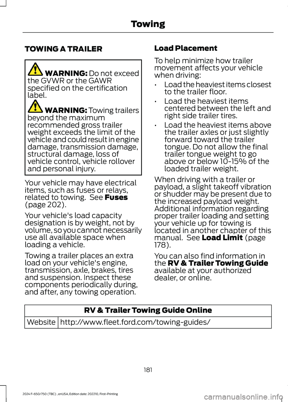
TOWING A TRAILER
WARNING: Do not exceedthe GVWR or the GAWRspecified on the certificationlabel.
WARNING: Towing trailersbeyond the maximumrecommended gross trailerweight exceeds the limit of thevehicle and could result in enginedamage, transmission damage,structural damage, loss ofvehicle control, vehicle rolloverand personal injury.
Your vehicle may have electricalitems, such as fuses or relays,related to towing. See Fuses(page 202).
Your vehicle's load capacitydesignation is by weight, not byvolume, so you cannot necessarilyuse all available space whenloading a vehicle.
Towing a trailer places an extraload on your vehicle's engine,transmission, axle, brakes, tiresand suspension. Inspect thesecomponents periodically during,and after, any towing operation.
Load Placement
To help minimize how trailermovement affects your vehiclewhen driving:
•Load the heaviest items closestto the trailer floor.
•Load the heaviest itemscentered between the left andright side trailer tires.
•Load the heaviest items abovethe trailer axles or just slightlyforward toward the trailertongue. Do not allow the finaltrailer tongue weight to goabove or below 10-15% of theloaded trailer weight.
When driving with a trailer orpayload, a slight takeoff vibrationor shudder may be present due tothe increased payload weight.Additional information regardingproper trailer loading and settingyour vehicle up for towing islocated in another chapter of thismanual. See Load Limit (page178).
You can also find information inthe RV & Trailer Towing Guideavailable at your authorizeddealer, or online.
RV & Trailer Towing Guide Online
http://www.fleet.ford.com/towing-guides/Website
181
2024 F-650/750 (TBC) , enUSA, Edition date: 202210, First-PrintingTowing
Page 207 of 386
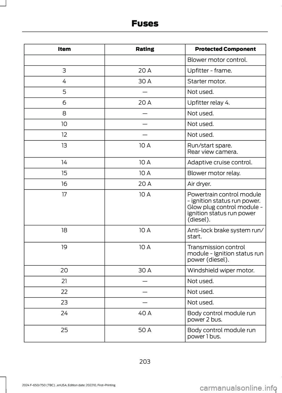
Protected ComponentRatingItem
Blower motor control.
Upfitter - frame.20 A3
Starter motor.30 A4
Not used.—5
Upfitter relay 4.20 A6
Not used.—8
Not used.—10
Not used.—12
Run/start spare.10 A13Rear view camera.
Adaptive cruise control.10 A14
Blower motor relay.10 A15
Air dryer.20 A16
Powertrain control module- ignition status run power.10 A17
Glow plug control module -ignition status run power(diesel).
Anti-lock brake system run/start.10 A18
Transmission controlmodule - Ignition status runpower (diesel).
10 A19
Windshield wiper motor.30 A20
Not used.—21
Not used.—22
Not used.—23
Body control module runpower 2 bus.40 A24
Body control module runpower 1 bus.50 A25
203
2024 F-650/750 (TBC) , enUSA, Edition date: 202210, First-PrintingFuses
Page 208 of 386
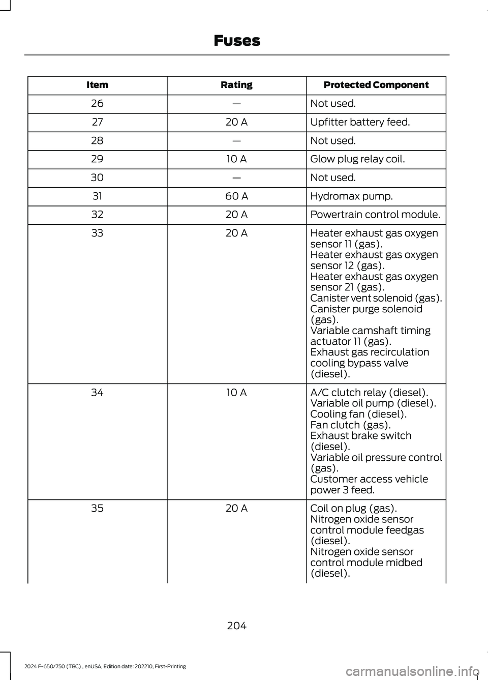
Protected ComponentRatingItem
Not used.—26
Upfitter battery feed.20 A27
Not used.—28
Glow plug relay coil.10 A29
Not used.—30
Hydromax pump.60 A31
Powertrain control module.20 A32
Heater exhaust gas oxygensensor 11 (gas).20 A33
Heater exhaust gas oxygensensor 12 (gas).Heater exhaust gas oxygensensor 21 (gas).Canister vent solenoid (gas).Canister purge solenoid(gas).Variable camshaft timingactuator 11 (gas).Exhaust gas recirculationcooling bypass valve(diesel).
A/C clutch relay (diesel).10 A34Variable oil pump (diesel).Cooling fan (diesel).Fan clutch (gas).Exhaust brake switch(diesel).Variable oil pressure control(gas).Customer access vehiclepower 3 feed.
Coil on plug (gas).20 A35Nitrogen oxide sensorcontrol module feedgas(diesel).Nitrogen oxide sensorcontrol module midbed(diesel).
204
2024 F-650/750 (TBC) , enUSA, Edition date: 202210, First-PrintingFuses
Page 209 of 386
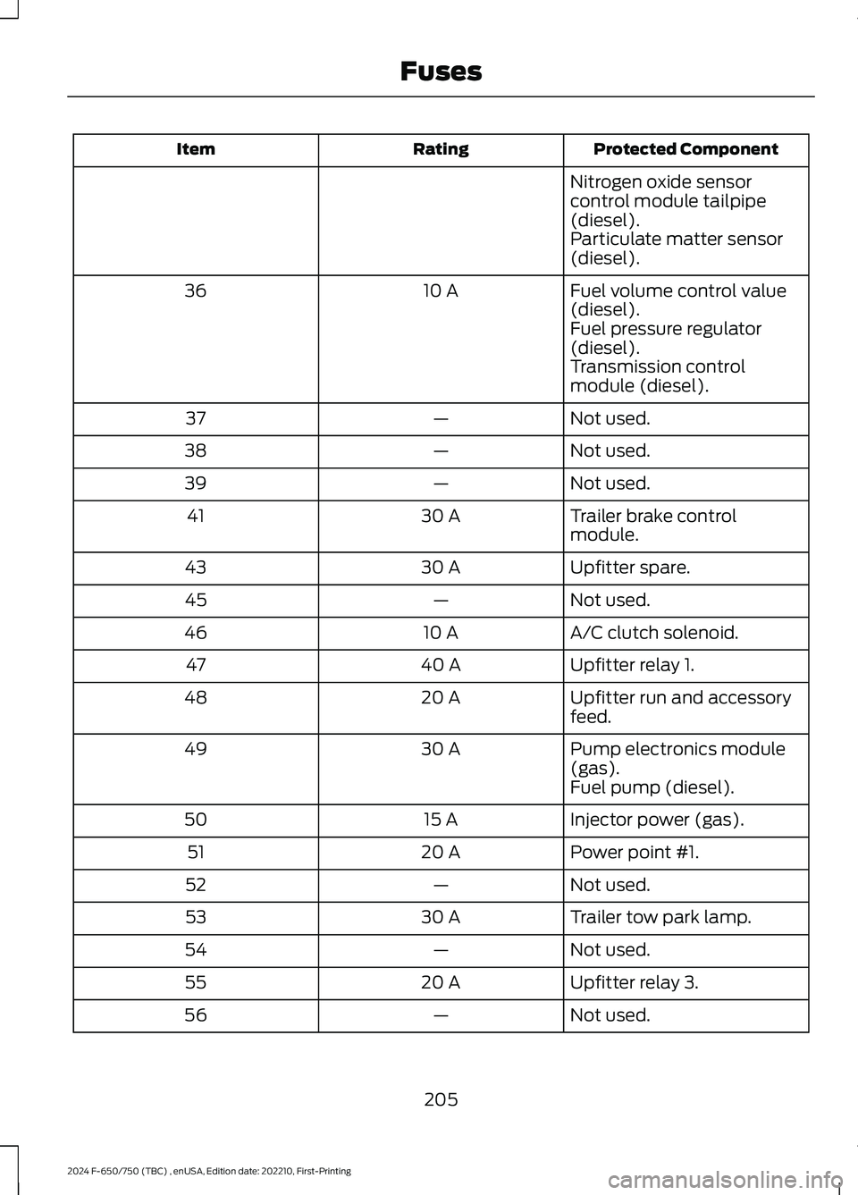
Protected ComponentRatingItem
Nitrogen oxide sensorcontrol module tailpipe(diesel).Particulate matter sensor(diesel).
Fuel volume control value(diesel).10 A36
Fuel pressure regulator(diesel).Transmission controlmodule (diesel).
Not used.—37
Not used.—38
Not used.—39
Trailer brake controlmodule.30 A41
Upfitter spare.30 A43
Not used.—45
A/C clutch solenoid.10 A46
Upfitter relay 1.40 A47
Upfitter run and accessoryfeed.20 A48
Pump electronics module(gas).30 A49
Fuel pump (diesel).
Injector power (gas).15 A50
Power point #1.20 A51
Not used.—52
Trailer tow park lamp.30 A53
Not used.—54
Upfitter relay 3.20 A55
Not used.—56
205
2024 F-650/750 (TBC) , enUSA, Edition date: 202210, First-PrintingFuses
Page 210 of 386
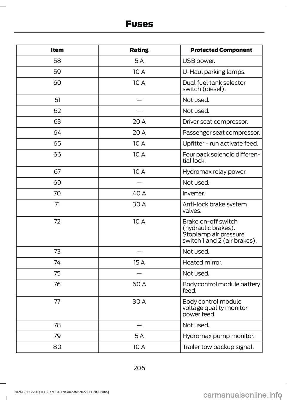
Protected ComponentRatingItem
USB power.5 A58
U-Haul parking lamps.10 A59
Dual fuel tank selectorswitch (diesel).10 A60
Not used.—61
Not used.—62
Driver seat compressor.20 A63
Passenger seat compressor.20 A64
Upfitter - run activate feed.10 A65
Four pack solenoid differen-tial lock.10 A66
Hydromax relay power.10 A67
Not used.—69
Inverter.40 A70
Anti-lock brake systemvalves.30 A71
Brake on-off switch(hydraulic brakes).10 A72
Stoplamp air pressureswitch 1 and 2 (air brakes).
Not used.—73
Heated mirror.15 A74
Not used.—75
Body control module batteryfeed.60 A76
Body control modulevoltage quality monitorpower feed.
30 A77
Not used.—78
Hydromax pump monitor.5 A79
Trailer tow backup signal.10 A80
206
2024 F-650/750 (TBC) , enUSA, Edition date: 202210, First-PrintingFuses
Page 211 of 386
Protected ComponentRatingItem
Not used.—81
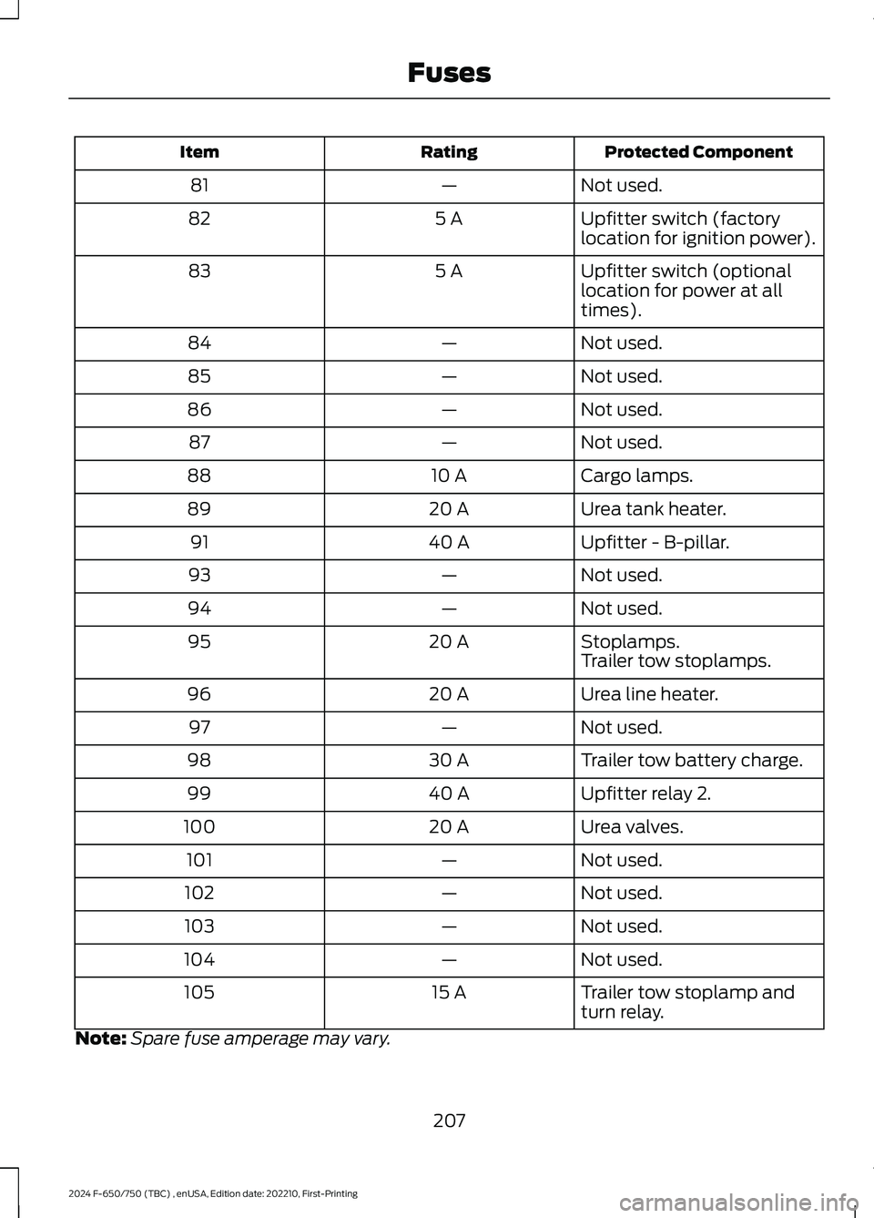
Upfitter switch (factorylocation for ignition power).5 A82
Upfitter switch (optionallocation for power at alltimes).
5 A83
Not used.—84
Not used.—85
Not used.—86
Not used.—87
Cargo lamps.10 A88
Urea tank heater.20 A89
Upfitter - B-pillar.40 A91
Not used.—93
Not used.—94
Stoplamps.20 A95Trailer tow stoplamps.
Urea line heater.20 A96
Not used.—97
Trailer tow battery charge.30 A98
Upfitter relay 2.40 A99
Urea valves.20 A100
Not used.—101
Not used.—102
Not used.—103
Not used.—104
Trailer tow stoplamp andturn relay.15 A105
Note:Spare fuse amperage may vary.
207
2024 F-650/750 (TBC) , enUSA, Edition date: 202210, First-PrintingFuses
Page 214 of 386
Protected ComponentRatingItem
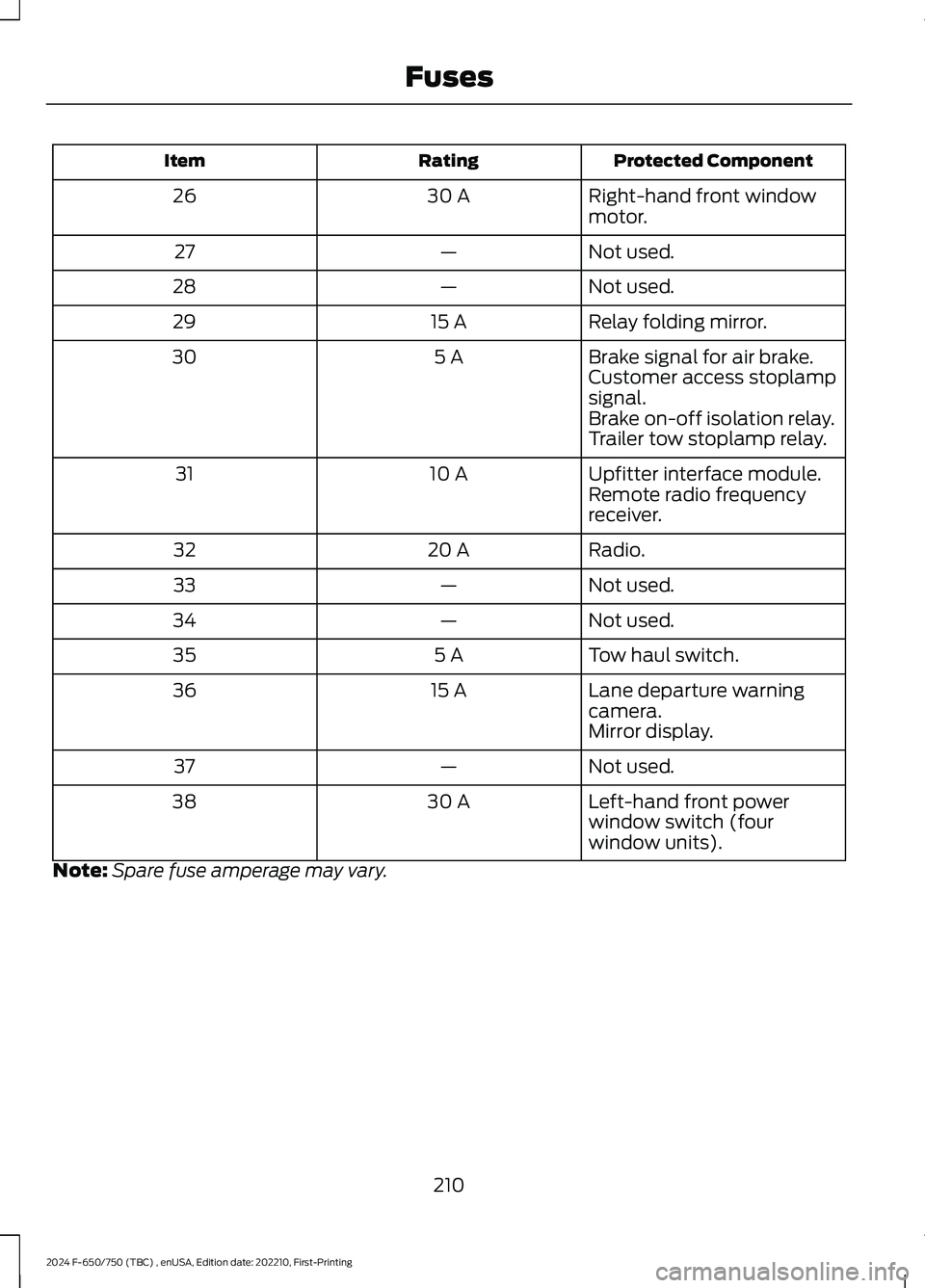
Right-hand front windowmotor.30 A26
Not used.—27
Not used.—28
Relay folding mirror.15 A29
Brake signal for air brake.5 A30Customer access stoplampsignal.Brake on-off isolation relay.Trailer tow stoplamp relay.
Upfitter interface module.10 A31Remote radio frequencyreceiver.
Radio.20 A32
Not used.—33
Not used.—34
Tow haul switch.5 A35
Lane departure warningcamera.15 A36
Mirror display.
Not used.—37
Left-hand front powerwindow switch (fourwindow units).
30 A38
Note:Spare fuse amperage may vary.
210
2024 F-650/750 (TBC) , enUSA, Edition date: 202210, First-PrintingFuses
Page 325 of 386
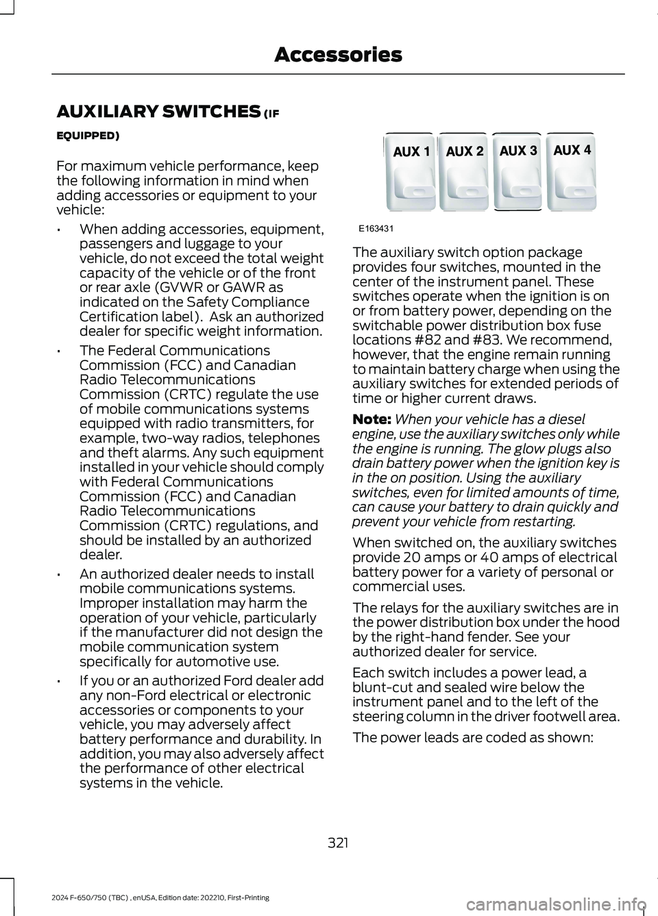
AUXILIARY SWITCHES (IF
EQUIPPED)
For maximum vehicle performance, keepthe following information in mind whenadding accessories or equipment to yourvehicle:
•When adding accessories, equipment,passengers and luggage to yourvehicle, do not exceed the total weightcapacity of the vehicle or of the frontor rear axle (GVWR or GAWR asindicated on the Safety ComplianceCertification label). Ask an authorizeddealer for specific weight information.
•The Federal CommunicationsCommission (FCC) and CanadianRadio TelecommunicationsCommission (CRTC) regulate the useof mobile communications systemsequipped with radio transmitters, forexample, two-way radios, telephonesand theft alarms. Any such equipmentinstalled in your vehicle should complywith Federal CommunicationsCommission (FCC) and CanadianRadio TelecommunicationsCommission (CRTC) regulations, andshould be installed by an authorizeddealer.
•An authorized dealer needs to installmobile communications systems.Improper installation may harm theoperation of your vehicle, particularlyif the manufacturer did not design themobile communication systemspecifically for automotive use.
•If you or an authorized Ford dealer addany non-Ford electrical or electronicaccessories or components to yourvehicle, you may adversely affectbattery performance and durability. Inaddition, you may also adversely affectthe performance of other electricalsystems in the vehicle.
The auxiliary switch option packageprovides four switches, mounted in thecenter of the instrument panel. Theseswitches operate when the ignition is onor from battery power, depending on theswitchable power distribution box fuselocations #82 and #83. We recommend,however, that the engine remain runningto maintain battery charge when using theauxiliary switches for extended periods oftime or higher current draws.
Note:When your vehicle has a dieselengine, use the auxiliary switches only whilethe engine is running. The glow plugs alsodrain battery power when the ignition key isin the on position. Using the auxiliaryswitches, even for limited amounts of time,can cause your battery to drain quickly andprevent your vehicle from restarting.
When switched on, the auxiliary switchesprovide 20 amps or 40 amps of electricalbattery power for a variety of personal orcommercial uses.
The relays for the auxiliary switches are inthe power distribution box under the hoodby the right-hand fender. See yourauthorized dealer for service.
Each switch includes a power lead, ablunt-cut and sealed wire below theinstrument panel and to the left of thesteering column in the driver footwell area.
The power leads are coded as shown:
321
2024 F-650/750 (TBC) , enUSA, Edition date: 202210, First-PrintingAccessoriesE163431
Page 326 of 386
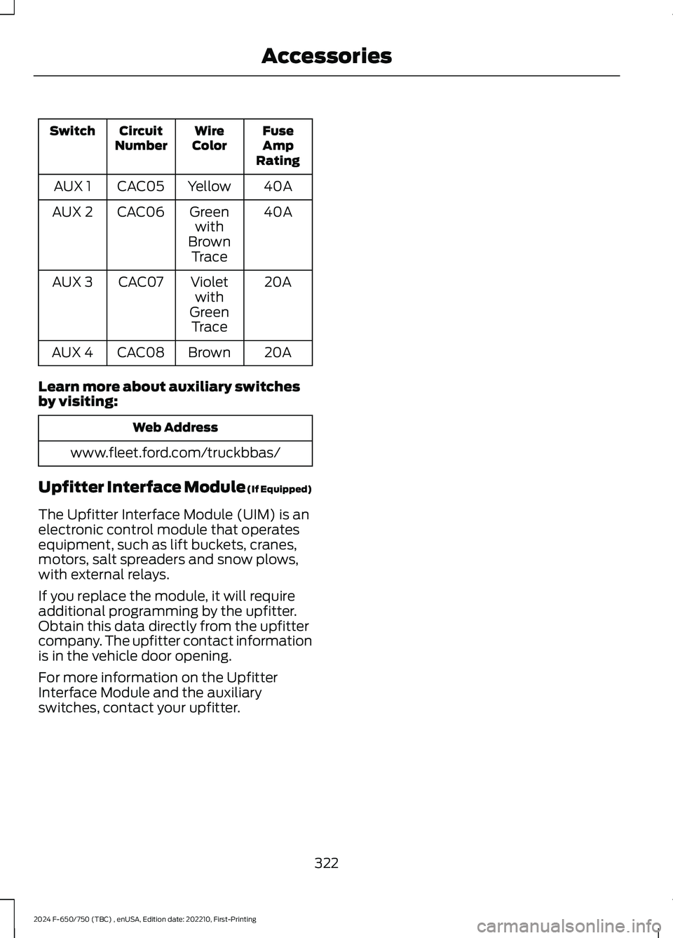
FuseAmpRating
WireColorCircuitNumberSwitch
40AYellowCAC05AUX 1
40AGreenwithBrownTrace
CAC06AUX 2
20AVioletwithGreenTrace
CAC07AUX 3
20ABrownCAC08AUX 4
Learn more about auxiliary switchesby visiting:
Web Address
www.fleet.ford.com/truckbbas/
Upfitter Interface Module (If Equipped)
The Upfitter Interface Module (UIM) is anelectronic control module that operatesequipment, such as lift buckets, cranes,motors, salt spreaders and snow plows,with external relays.
If you replace the module, it will requireadditional programming by the upfitter.Obtain this data directly from the upfittercompany. The upfitter contact informationis in the vehicle door opening.
For more information on the UpfitterInterface Module and the auxiliaryswitches, contact your upfitter.
322
2024 F-650/750 (TBC) , enUSA, Edition date: 202210, First-PrintingAccessories