FORD F750 2000 10.G Owners Manual
Manufacturer: FORD, Model Year: 2000, Model line: F750, Model: FORD F750 2000 10.GPages: 208, PDF Size: 1.08 MB
Page 111 of 208
The PTO gear is in constant mesh with the drive gear in the torque
converter housing. A friction clutch or constant drive is used to transmit
power to the PTO.
Power take-off (PTO) operation on vehicles equipped with a
Caterpillar 3126E engine
If your vehicle is equipped with a Caterpillar 3126E engine, the PTO will
only operate if the vehicle is in Neutral. This feature can be overriden by
a special service tool; see your dealer or service representative for more
information.
MAXIMUM VEHICLE LOADING
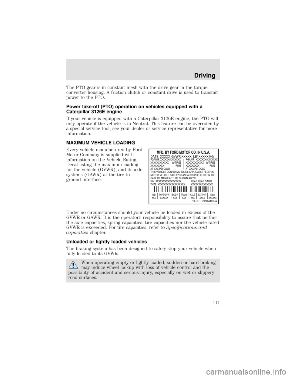
Every vehicle manufactured by Ford
Motor Company is supplied with
information on the Vehicle Rating
Decal listing the maximum loading
for the vehicle (GVWR), and its axle
systems (GAWR) at the tire to
ground interface.
Under no circumstances should your vehicle be loaded in excess of the
GVWR or GAWR. It is the operator’s responsibility to assure that neither
the axle capacities, spring capacities, tire capacities nor the vehicle rated
GVWR is exceeded. For tire capacities, refer toSpecifications and
capacitieschapter.
Unloaded or lightly loaded vehicles
The braking system has been designed to safely stop your vehicle when
fully loaded to its GVWR.
When operating empty or lightly loaded, sudden or hard braking
may induce wheel lockup with loss of vehicle control and the
possibility of accident and serious injury, especially on wet or slippery
road surfaces.
MFD. BY FORD MOTOR CO. IN U.S.A.
WB TYPE/GVW BODY TRANS AXLE EXT PNT DSO
XXX XXXXXX XXX XXX XXX XXXX XXXXXX
∇FOHT-15294A10-GA
DATE: XXXXX GVWR:XXXXX LB/ XXXXX KGFGAWR: XXXXXX/XXXXXXX RGAWR: XXXXXXX/XXXXXXX
XXXXXXXXXXXX W/TIRES XXXXXXXXXXXX W/TIRES
XXXXXXXXX RIMS XXXXXXXXX RIMS
AT XXX PSI COLD AT XXX PSI COLD
THIS VEHICLE CONFORMS TO ALL APPLICABLE FEDERAL
MOTOR VEHICLE SAFETY STANDARDS IN EFFECT ON THE
DATE OF MANUFACTURE SHOWN ABOVE.
VIN: XXXXXXXXXXXXXXXXX REAR REAR GAWR
TYPE: XXXXXXXXXXXXXXXXXX XXXXXXX/XXXXXXX
Driving
111
Page 112 of 208

Driving through water
Do not drive quickly through standing water, especially if the depth is
unknown. Traction or brake capability may be limited and if the ignition
system gets wet, your engine may stall. Water may also enter your
engine’s air intake and severely damage your engine.
If driving through deep or standing water is unavoidable, proceed very
slowly. Never drive through water that is higher than the bottom of the
hubs (for trucks) or the bottom of the wheel rims (for cars).
Once through the water, always try the brakes. Wet brakes do not stop
the vehicle as effectively as dry brakes. Drying can be improved by
moving your vehicle slowly while applying light pressure on the brake
pedal.
Driving through deep water where the transmission vent tube is
submerged may allow water into the transmission and cause
internal transmission damage.
FUEL CONSUMPTION IMPROVEMENT MEASURES
There are two important factors you can control to improve fuel
economy: the mechanical condition of your vehicle and how you drive it.
A properly maintained vehicle will deliver better performance than a
neglected vehicle. Always follow your maintenance schedule to keep your
vehicle in top operating condition.
Also, your driving habits have a significant influence on use of fuel. By
following these suggestions, you can stretch your fuel use:
•Avoid changes in speed as much as possible.
•Anticipate changing traffic conditions. Sudden stops and fast
acceleration waste fuel.
•Avoid extensive idling.
•Do not drive with your foot resting on the brake pedal.
Driving
112
Page 113 of 208

WINTER FRONTS
If using an aftermarket winter front (not recommended), it must have a
permanent opening directly in line with the center of the fan drive. The
minimum opening size must be at least 774 square cm (120 square
inches).
The use of an aftermarket winter front or other air flow restriction
device mounted in front of the radiator is not recommended on vehicles
equipped with chassis mounted air-to-air aftercooling. Air flow restriction
will cause high exhaust temperatures, power loss, excessive fan usage
and a reduction in fuel economy.
Driving
113
Page 114 of 208
GETTING ROADSIDE ASSISTANCE
To fully assist you should you have a vehicle concern, Ford offers a
complimentary roadside assistance program. This program is separate
from the New Vehicle Limited Warranty. The service is available:
•24–hours, seven days a week
•for the New Vehicle Limited Warranty period (U.S.) of two years
(unlimited miles)
Roadside assistance will cover:
•jump-starts
•lock-out assistance
•towing to the nearest Ford Motor Company dealership, or towing to
your selling dealership if within 56 km (35 miles). Even non-warranty
related tows, like accidents or getting stuck in the mud or snow, are
covered (some exclusions apply, such as impound towing or
repossession).
Using roadside assistance
Complete the roadside assistance identification card and place it in your
wallet for quick reference. This card is found in the Owner Guide
portfolio in the glove compartment.
To receive roadside assistance in the United States, call 1-800-241-3673.
In Canada call 1–800–665–2006.
Should you need to arrange roadside assistance for yourself, Ford will
reimburse a reasonable amount. To obtain information about
reimbursement, call 1-800-241-3673.
Roadside emergencies
114
Page 115 of 208
HAZARD FLASHER
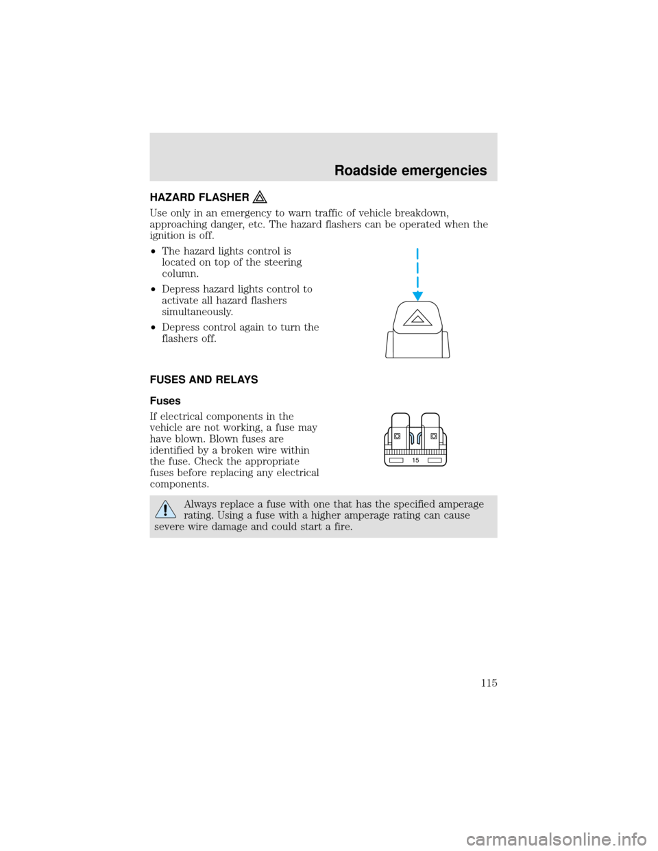
Use only in an emergency to warn traffic of vehicle breakdown,
approaching danger, etc. The hazard flashers can be operated when the
ignition is off.
•The hazard lights control is
located on top of the steering
column.
•Depress hazard lights control to
activate all hazard flashers
simultaneously.
•Depress control again to turn the
flashers off.
FUSES AND RELAYS
Fuses
If electrical components in the
vehicle are not working, a fuse may
have blown. Blown fuses are
identified by a broken wire within
the fuse. Check the appropriate
fuses before replacing any electrical
components.
Always replace a fuse with one that has the specified amperage
rating. Using a fuse with a higher amperage rating can cause
severe wire damage and could start a fire.
15
Roadside emergencies
115
Page 116 of 208
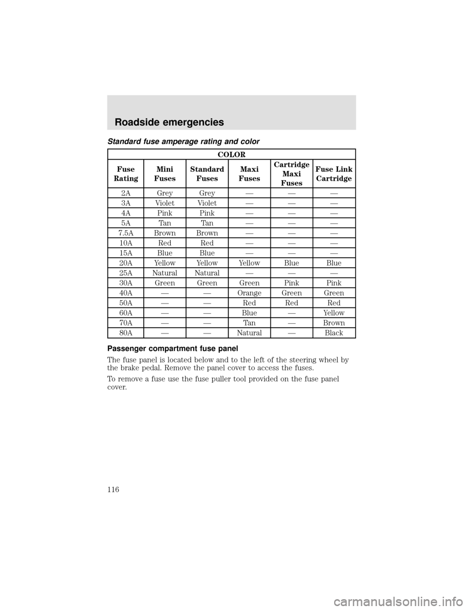
Standard fuse amperage rating and color
COLOR
Fuse
RatingMini
FusesStandard
FusesMaxi
FusesCartridge
Maxi
FusesFuse Link
Cartridge
2A Grey Grey———
3A Violet Violet———
4A Pink Pink———
5A Tan Tan———
7.5A Brown Brown———
10A Red Red———
15A Blue Blue———
20A Yellow Yellow Yellow Blue Blue
25A Natural Natural———
30A Green Green Green Pink Pink
40A——Orange Green Green
50A——Red Red Red
60A——Blue—Yellow
70A——Ta n—Brown
80A——Natural—Black
Passenger compartment fuse panel
The fuse panel is located below and to the left of the steering wheel by
the brake pedal. Remove the panel cover to access the fuses.
To remove a fuse use the fuse puller tool provided on the fuse panel
cover.
Roadside emergencies
116
Page 117 of 208

The fuses are coded as follows.
Fuse/Relay
LocationFuse Amp
RatingPassenger Compartment
Fuse Panel Description
1 20A Horn
2 15A Turn/Hazard Lamps
3 20A Cigar Lighter
4 10A Diagnostic Connectors
5 15A Back-Up Lamps, DRL Relays, Blend Door
Actuator
6—Not Used
7—Not Used
8 5A Radio, GEM
9 5A Switch Illumination (Headlamp, Power
Windows, Power Door Locks), Power
Window Relay
10—Not Used
11 30A Wiper Motor, Washer Pump Relay
12 10A Stoplamp Switch (Hydraulic Vehicles Only)
Relay #1
Relay #2
Relay #3
Horn
Relay #4
Relay #5 One Touch
Down Interior
Lamps#1
#12#22
#2
#3
#4
#5
#6
#7
#8
#9
#10
#11#13
#23
#14
#15
#16
#17#24
#25
#26
#27
#18
#28
#19
#29
#20
#21#30
#31
Roadside emergencies
117
Page 118 of 208
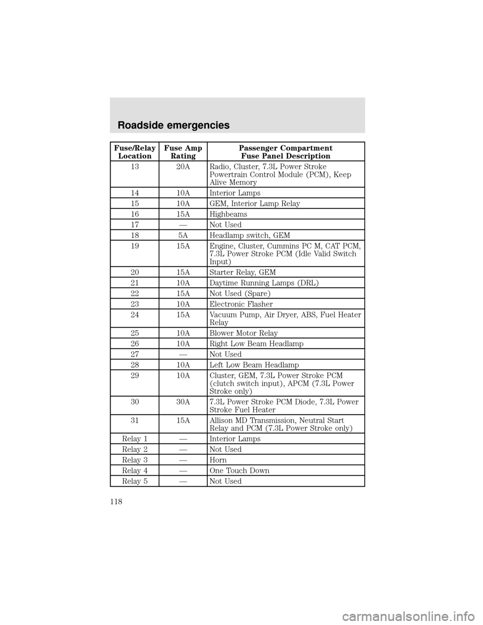
Fuse/Relay
LocationFuse Amp
RatingPassenger Compartment
Fuse Panel Description
13 20A Radio, Cluster, 7.3L Power Stroke
Powertrain Control Module (PCM), Keep
Alive Memory
14 10A Interior Lamps
15 10A GEM, Interior Lamp Relay
16 15A Highbeams
17—Not Used
18 5A Headlamp switch, GEM
19 15A Engine, Cluster, Cummins PC M, CAT PCM,
7.3L Power Stroke PCM (Idle Valid Switch
Input)
20 15A Starter Relay, GEM
21 10A Daytime Running Lamps (DRL)
22 15A Not Used (Spare)
23 10A Electronic Flasher
24 15A Vacuum Pump, Air Dryer, ABS, Fuel Heater
Relay
25 10A Blower Motor Relay
26 10A Right Low Beam Headlamp
27—Not Used
28 10A Left Low Beam Headlamp
29 10A Cluster, GEM, 7.3L Power Stroke PCM
(clutch switch input), APCM (7.3L Power
Stroke only)
30 30A 7.3L Power Stroke PCM Diode, 7.3L Power
Stroke Fuel Heater
31 15A Allison MD Transmission, Neutral Start
Relay and PCM (7.3L Power Stroke only)
Relay 1—Interior Lamps
Relay 2—Not Used
Relay 3—Horn
Relay 4—One Touch Down
Relay 5—Not Used
Roadside emergencies
118
Page 119 of 208
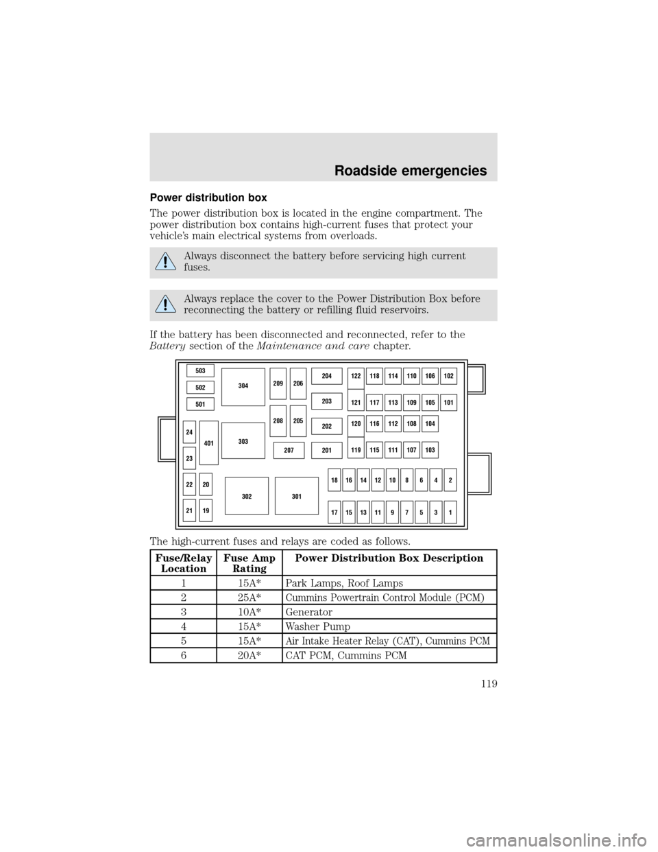
Power distribution box
The power distribution box is located in the engine compartment. The
power distribution box contains high-current fuses that protect your
vehicle’s main electrical systems from overloads.
Always disconnect the battery before servicing high current
fuses.
Always replace the cover to the Power Distribution Box before
reconnecting the battery or refilling fluid reservoirs.
If the battery has been disconnected and reconnected, refer to the
Batterysection of theMaintenance and carechapter.
The high-current fuses and relays are coded as follows.
Fuse/Relay
LocationFuse Amp
RatingPower Distribution Box Description
1 15A* Park Lamps, Roof Lamps
2 25A*
Cummins Powertrain Control Module (PCM)
3 10A* Generator
4 15A* Washer Pump
5 15A*
Air Intake Heater Relay (CAT), Cummins PCM
6 20A* CAT PCM, Cummins PCM
503
304
303
302301
502
501
207201
202
203
204122118114110106102
121117113109105101
120116112108104
119115111107103
24
209206
208
18161412108642
1715131197531
205
23
22
21
401
20
19
Roadside emergencies
119
Page 120 of 208
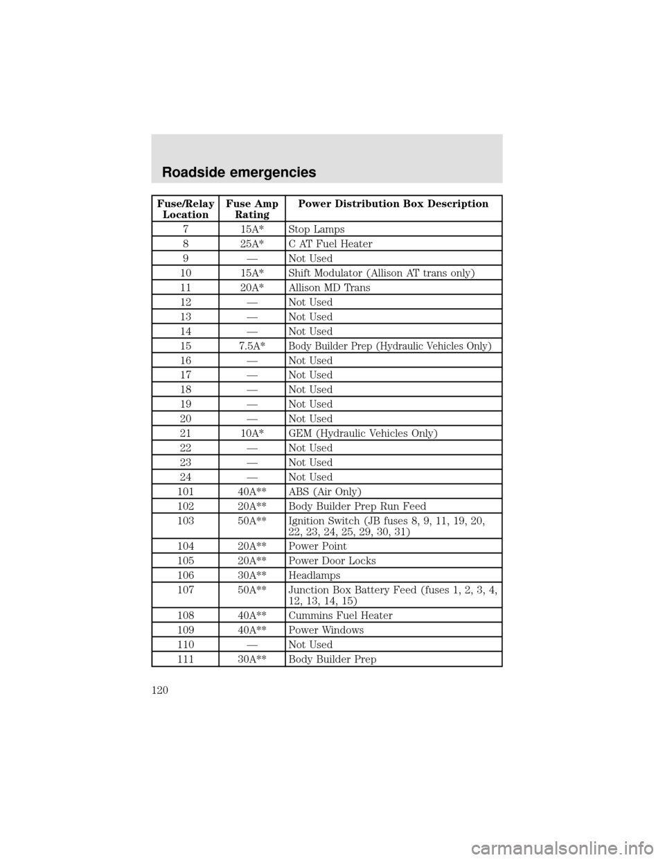
Fuse/Relay
LocationFuse Amp
RatingPower Distribution Box Description
7 15A* Stop Lamps
8 25A* C AT Fuel Heater
9—Not Used
10 15A* Shift Modulator (Allison AT trans only)
11 20A* Allison MD Trans
12—Not Used
13—Not Used
14—Not Used
15 7.5A*
Body Builder Prep (Hydraulic Vehicles Only)
16—Not Used
17—Not Used
18—Not Used
19—Not Used
20—Not Used
21 10A* GEM (Hydraulic Vehicles Only)
22—Not Used
23—Not Used
24—Not Used
101 40A** ABS (Air Only)
102 20A** Body Builder Prep Run Feed
103 50A** Ignition Switch (JB fuses 8, 9, 11, 19, 20,
22, 23, 24, 25, 29, 30, 31)
104 20A** Power Point
105 20A** Power Door Locks
106 30A** Headlamps
107 50A** Junction Box Battery Feed (fuses 1, 2, 3, 4,
12, 13, 14, 15)
108 40A** Cummins Fuel Heater
109 40A** Power Windows
110—Not Used
111 30A** Body Builder Prep
Roadside emergencies
120