FORD F750 2000 10.G Owners Manual
Manufacturer: FORD, Model Year: 2000, Model line: F750, Model: FORD F750 2000 10.GPages: 208, PDF Size: 1.08 MB
Page 121 of 208

Fuse/Relay
LocationFuse Amp
RatingPower Distribution Box Description
112 40A** Blower Motor
113—Not Used
114—Not Used
115 40A** Ignition Switch (JB fuses 5, 8, 9, 11, 21)
116 30A** Body Builder Prep
117 20A** 7.3L Power Stroke PCM
118 30A** IDM (7.3L Power Stroke only)
119
12060A** Hydraulic ABS
121
12260A** Hydromax Motor
201—Washer Pump Relay
202—Wiper Speed Relay
203—Wiper Run/Park Relay
204—Cummins VP44 Relay/7.3L Power Stroke
Neutral Start Relay
205—Right Hand Stop/Turn Relay
206—Left Hand Stop/Turn Relay
207—Shift Modulator Relay
208—Backup Lamps Relay
209—Stop Lamps Relay
301—Fuel Heater Relay (CAT and Cummins
only)/7.3L Power Stroke PCM Relay
302—Park Lamps Relay
303—Blower Motor Relay
304—Air ABS Relay
401—Not Used
501—Not Used
502—Not Used
503 Diode 7.3L Power Stroke PCM Diode
* Mini Fuses ** Maxi Fuses
Roadside emergencies
121
Page 122 of 208
JUMP STARTING YOUR VEHICLE
The gases around the battery can explode if exposed to flames,
sparks, or lit cigarettes. An explosion could result in injury or
vehicle damage.
Do not push start your vehicle. You could damage the catalytic
converter.
Batteries contain sulfuric acid which burns skin, eyes, and
clothing.
Preparing your vehicle
Also see the label on the battery.
1. Use only a 12–volt supply to start your vehicle. If you connect your
battery to a 24–volt power supply you can damage your starter, ignition
system and other electrical components. Do not attach the jumper cables
to the glow plug relay as this could severely damage the glow plugs,
injector driver module and PCM.
2. Do not disconnect the battery of the disabled vehicle as this could
damage the vehicle’s electrical system.
3. Park the booster vehicle close to the disabled vehicle making sure
theydo nottouch. Set the parking brake on both vehicles and stay clear
of the engine cooling fan and other moving parts.
4. Check all battery terminals and remove any excessive corrosion before
you attach the battery cables.
5. Turn the heater fan on in both vehicles to protect any electrical
surges. Turn all other accessories off.
Roadside emergencies
122
Page 123 of 208
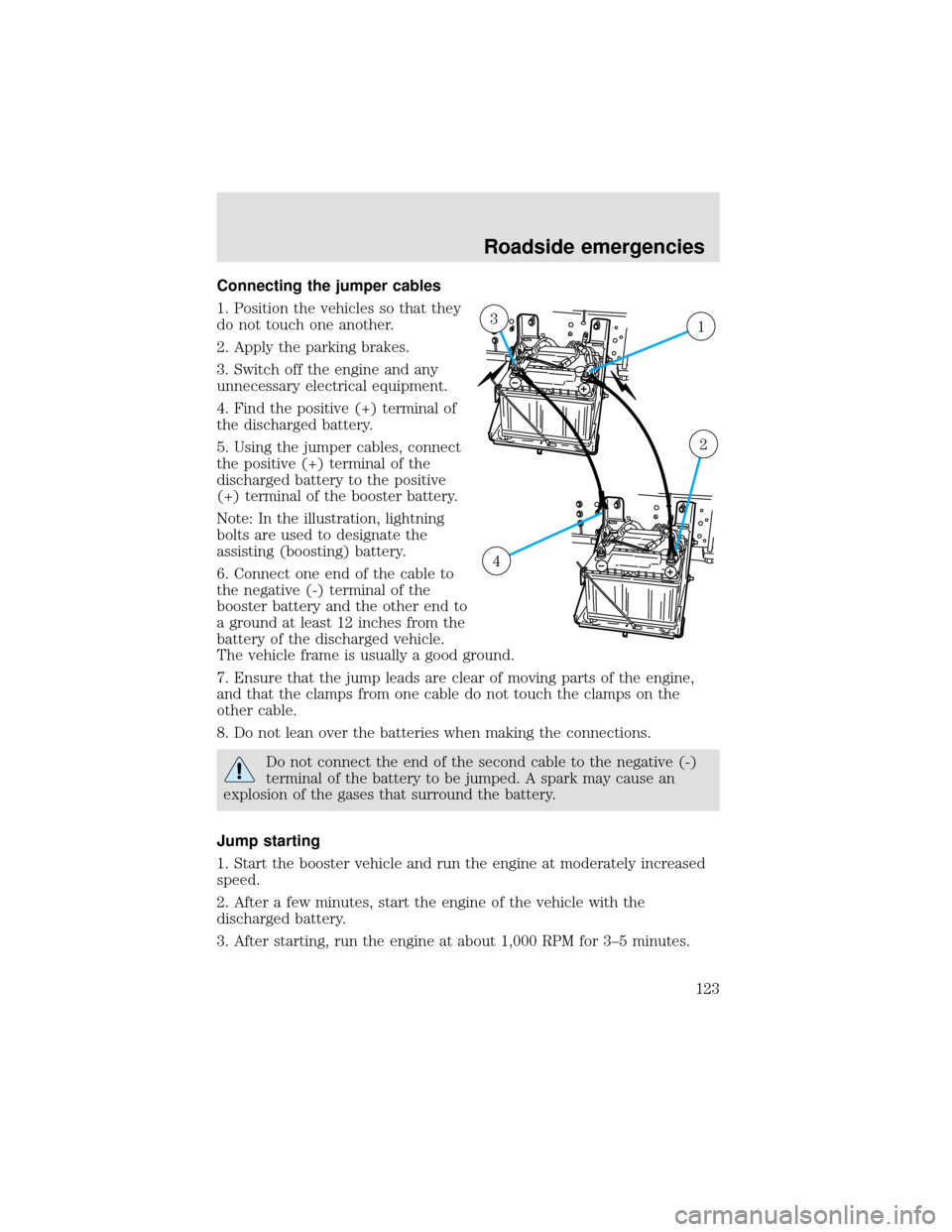
Connecting the jumper cables
1. Position the vehicles so that they
do not touch one another.
2. Apply the parking brakes.
3. Switch off the engine and any
unnecessary electrical equipment.
4. Find the positive (+) terminal of
the discharged battery.
5. Using the jumper cables, connect
the positive (+) terminal of the
discharged battery to the positive
(+) terminal of the booster battery.
Note: In the illustration, lightning
bolts are used to designate the
assisting (boosting) battery.
6. Connect one end of the cable to
the negative (-) terminal of the
booster battery and the other end to
a ground at least 12 inches from the
battery of the discharged vehicle.
The vehicle frame is usually a good ground.
7. Ensure that the jump leads are clear of moving parts of the engine,
and that the clamps from one cable do not touch the clamps on the
other cable.
8. Do not lean over the batteries when making the connections.
Do not connect the end of the second cable to the negative (-)
terminal of the battery to be jumped. A spark may cause an
explosion of the gases that surround the battery.
Jump starting
1. Start the booster vehicle and run the engine at moderately increased
speed.
2. After a few minutes, start the engine of the vehicle with the
discharged battery.
3. After starting, run the engine at about 1,000 RPM for 3–5 minutes.
13
2
4
Roadside emergencies
123
Page 124 of 208
Do not operate the starter longer than 30 seconds. Wait at least
two minutes between starting attempts to allow the starter to
cool. If the engine does not start after several attempts, call for
road service.
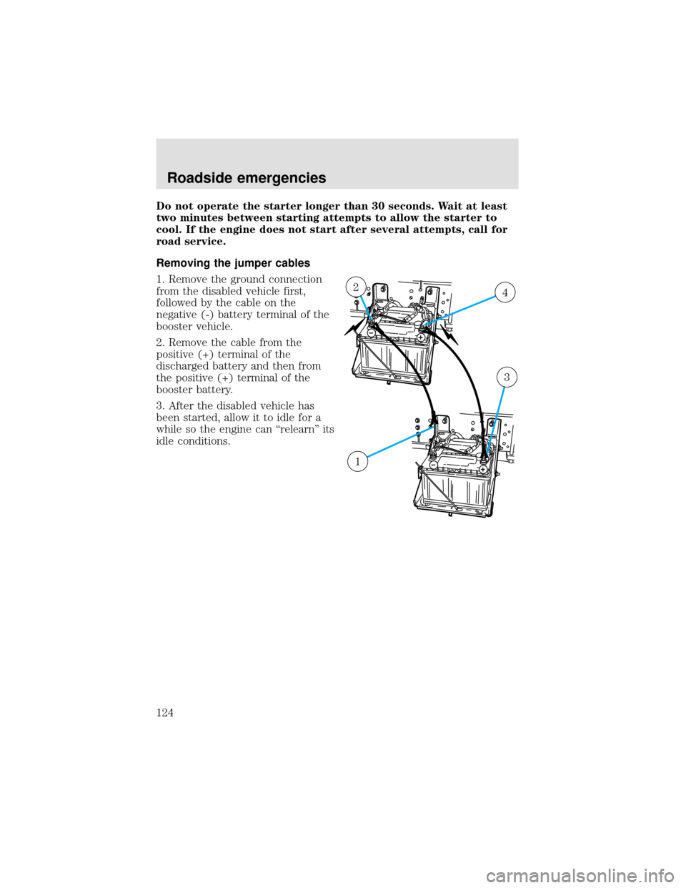
Removing the jumper cables
1. Remove the ground connection
from the disabled vehicle first,
followed by the cable on the
negative (-) battery terminal of the
booster vehicle.
2. Remove the cable from the
positive (+) terminal of the
discharged battery and then from
the positive (+) terminal of the
booster battery.
3. After the disabled vehicle has
been started, allow it to idle for a
while so the engine can“relearn”its
idle conditions.
42
3
1
Roadside emergencies
124
Page 125 of 208

WRECKER TOWING
Always unload your vehicle before towing it. The recommended method
of towing is with the drive wheels off the ground.
Before towing, make sure:
•the parking brake is released.
•if air pressure has been lost, to release the brakes manually.
Improper towing of the vehicle will not allow sufficient lubrication of the
transmission which may cause serious damage to internal transmission
components. Always follow the outlined towing procedures.
•To tow a vehicle on the front wheels,the steering wheel must be
in the straight ahead position. Secure the steering wheel with a
holding device (such as provided by a towing company).
•To tow a vehicle on the rear wheels,it will be necessary to remove
the drive axles or disconnect the driveshaft. If the drive axles are
removed, the ends of the axle housing must be sealed to prevent the
loss of axle lubricant during towing.
•To tow a vehicle with an inoperative rear axle,the rear wheels
must be raised onto a dolly or tow the vehicle on the front wheels.
•If your vehicle is equipped with tow hooks,chains must be
fastened directly to the tow hooks on the vehicle.
•If your vehicle is not equipped with tow hooks,chains must be
routed under the bottom edge of the bumper with a protection bar to
protect the bumper, and attached to the vehicle chassis. Under no
circumstances is the vehicle to be lifted or towed by attaching chains
directly to the bumper.
RAISING THE VEHICLE
Never lift the vehicle by the bumper. When raising the vehicle, attach
chains to or place the jack(s) directly beneath the main structural
members of the vehicle.
PUSH-STARTING YOUR VEHICLE
Avoid attempting to start a vehicle by pushing. Instead, use jumper
cables as described underJump starting your vehiclein theRoadside
emergencieschapter. Vehicles with an automatic transmission cannot be
started by pushing.
Roadside emergencies
125
Page 126 of 208
CHECKING UNDER THE HOOD
Opening the hood
The hood and fenders are held in position by a latch located on each
fender.
The parking brake must be fully set before opening the hood or
possible personal injury may occur.
If you must leave the engine running while checking under the
hood, do not allow any loose clothing, jewelry, hair or other
items to get near moving engine components or possible personal
injury may occur.
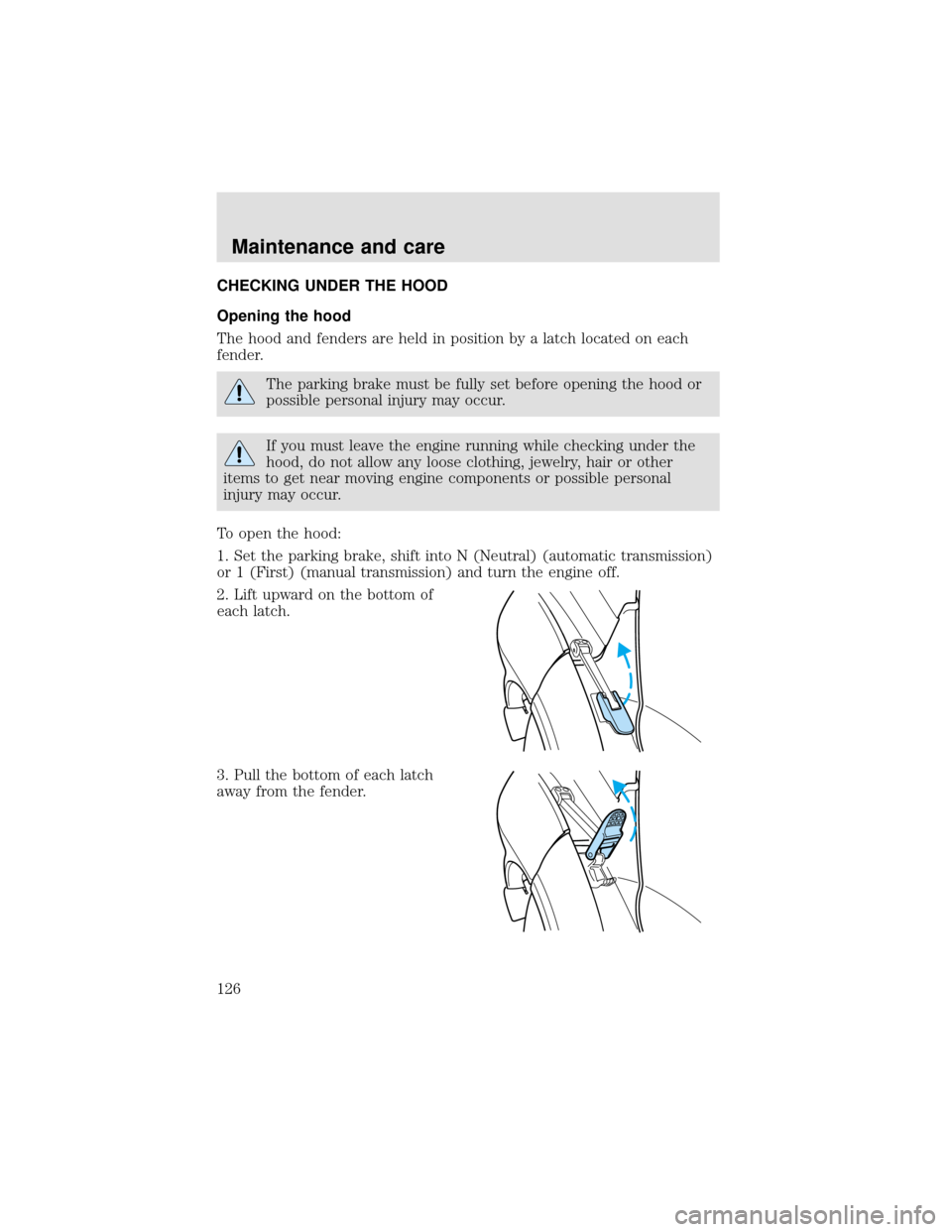
To open the hood:
1. Set the parking brake, shift into N (Neutral) (automatic transmission)
or 1 (First) (manual transmission) and turn the engine off.
2. Lift upward on the bottom of
each latch.
3. Pull the bottom of each latch
away from the fender.
Maintenance and care
126
Page 127 of 208
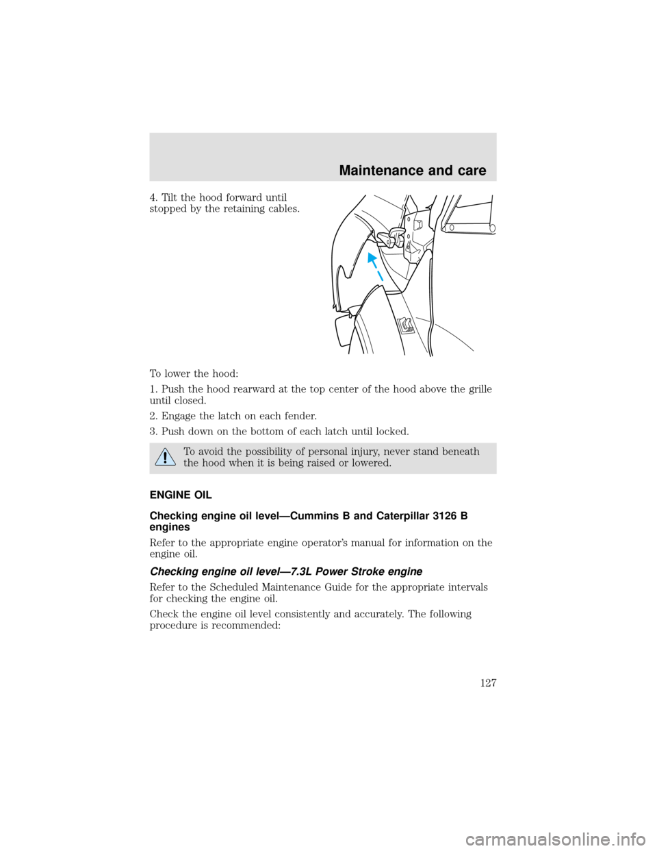
4. Tilt the hood forward until
stopped by the retaining cables.
To lower the hood:
1. Push the hood rearward at the top center of the hood above the grille
until closed.
2. Engage the latch on each fender.
3. Push down on the bottom of each latch until locked.
To avoid the possibility of personal injury, never stand beneath
the hood when it is being raised or lowered.
ENGINE OIL
Checking engine oil level—Cummins B and Caterpillar 3126 B
engines
Refer to the appropriate engine operator’s manual for information on the
engine oil.
Checking engine oil level—7.3L Power Stroke engine
Refer to the Scheduled Maintenance Guide for the appropriate intervals
for checking the engine oil.
Check the engine oil level consistently and accurately. The following
procedure is recommended:
Maintenance and care
127
Page 128 of 208
1. Start the engine and let it run until it reaches normal operating
temperature (the engine coolant temperature gauge indicator will be
near the center of the normal area between H and C).
2. Park the vehicle on level ground.
3. Set the parking brake and shift into N (Neutral) (automatic
transmission) or 1 (First) (manual transmission).
4. Turn off the engine and wait a few minutes for the oil to drain
completely into the oil pan.
5. Open the hood. Protect yourself from engine heat.
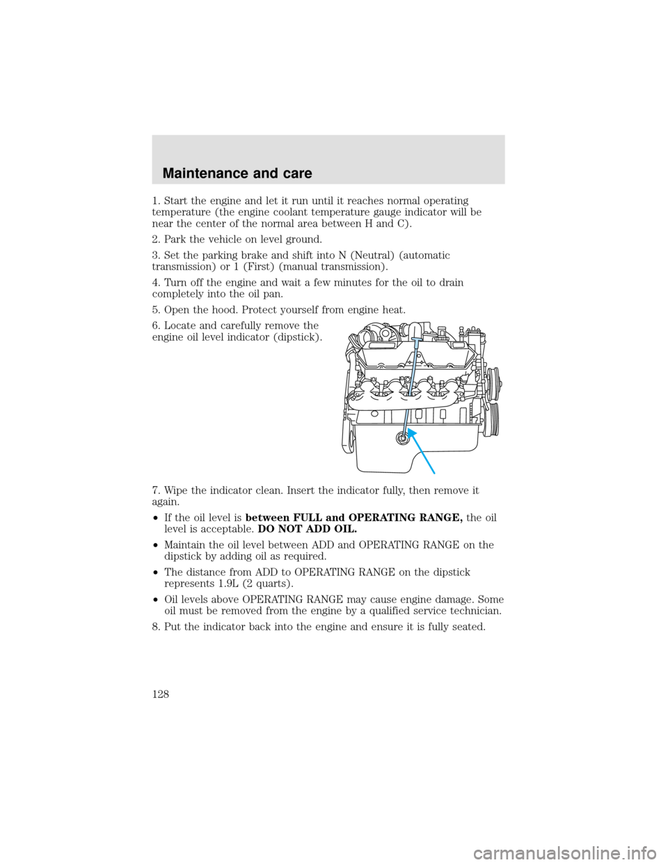
6. Locate and carefully remove the
engine oil level indicator (dipstick).
7. Wipe the indicator clean. Insert the indicator fully, then remove it
again.
•If the oil level isbetween FULL and OPERATING RANGE,the oil
level is acceptable.DO NOT ADD OIL.
•Maintain the oil level between ADD and OPERATING RANGE on the
dipstick by adding oil as required.
•The distance from ADD to OPERATING RANGE on the dipstick
represents 1.9L (2 quarts).
•Oil levels above OPERATING RANGE may cause engine damage. Some
oil must be removed from the engine by a qualified service technician.
8. Put the indicator back into the engine and ensure it is fully seated.
Maintenance and care
128
Page 129 of 208

Engine oil and filter recommendations—Cummins B and Caterpillar
3126 B engines
Refer to the appropriate engine operator’s manual for information on the
engine oil.
Engine oil and filter recommendations—7.3L Power Stroke engine
To help achieve proper engine performance and durability, it is important
that you:
•Use only engine lubricating oils and oil filters of the proper quality.
•Change the engine oil and filterno laterthan the recommended
service interval. Refer to the Scheduled Maintenance Guide for the
appropriate intervals for changing the engine oil and filter.
•Change your engine oil and filter more frequently if your vehicle
operation includes extended periods of idling or low-speed operation,
driving for a long time in cold temperatures or short driving distances.
Diesel engines require specially formulated oil to resist contamination.
Proper quality oils also provide maximum efficiency of the crankcase
ventilation system which reduces air pollution.
Use Motorcraft motor oil or an equivalent oil meeting Ford specification
WSS-M2C171–B or API service category designation CH-4/SJ. Do not use
oils labeled with only one of the category designations SG, SH, SJ, CE,
CF-4, CH-4 or CG-4, as they could cause engine damage.
Diesel engine oils with improved fuel economy properties (energy
conserving) are currently available. If you use an energy conserving oil,
be sure it meets Ford specification WSS-M2C171–B or API service
category designation CH-4/SJ and is of the proper viscosity grade for the
temperature range in which you expect to operate your vehicle. Some
energy conserving oils do not meet the requirements necessary for your
diesel engine.
Maintenance and care
129
Page 130 of 208
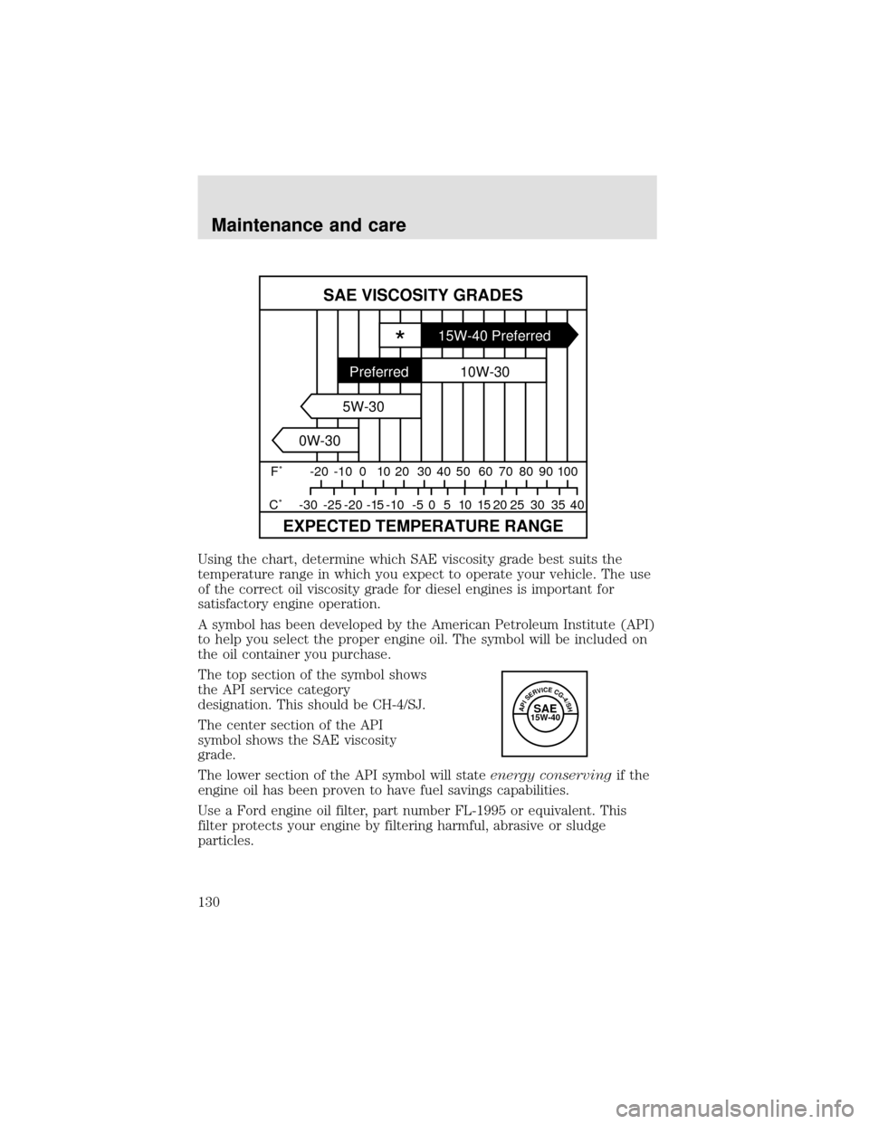
Using the chart, determine which SAE viscosity grade best suits the
temperature range in which you expect to operate your vehicle. The use
of the correct oil viscosity grade for diesel engines is important for
satisfactory engine operation.
A symbol has been developed by the American Petroleum Institute (API)
to help you select the proper engine oil. The symbol will be included on
the oil container you purchase.
The top section of the symbol shows
the API service category
designation. This should be CH-4/SJ.
The center section of the API
symbol shows the SAE viscosity
grade.
The lower section of the API symbol will stateenergy conservingif the
engine oil has been proven to have fuel savings capabilities.
Use a Ford engine oil filter, part number FL-1995 or equivalent. This
filter protects your engine by filtering harmful, abrasive or sludge
particles.
SAE VISCOSITY GRADES
EXPECTED TEMPERATURE RANGE
F˚ -20 -10 0 10 20 30 40
40 35 30 25 20 15 10 5 0 -5 -10 -15 -20 -25 -30 C˚50 60 70 80 90 100
*15W-40 Preferred
10W-30
5W-30
0W-30Preferred
APISERVICECG-4/SHSAE15W-40
Maintenance and care
130