battery FORD F750 2000 10.G Owners Manual
[x] Cancel search | Manufacturer: FORD, Model Year: 2000, Model line: F750, Model: FORD F750 2000 10.GPages: 208, PDF Size: 1.08 MB
Page 5 of 208
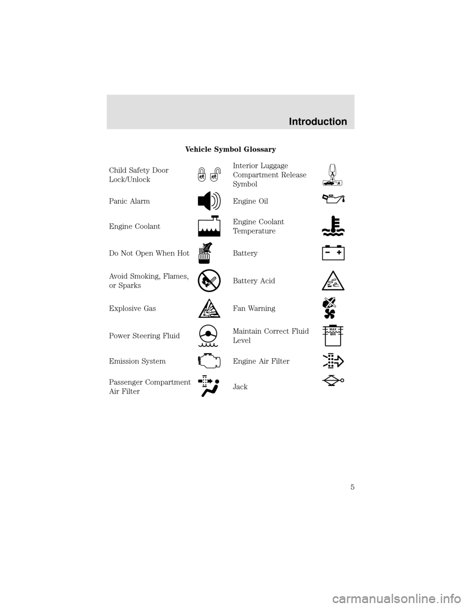
Vehicle Symbol Glossary
Child Safety Door
Lock/Unlock
Interior Luggage
Compartment Release
Symbol
Panic AlarmEngine Oil
Engine CoolantEngine Coolant
Temperature
Do Not Open When HotBattery
Avoid Smoking, Flames,
or SparksBattery Acid
Explosive GasFan Warning
Power Steering FluidMaintain Correct Fluid
LevelMAX
MIN
Emission SystemEngine Air Filter
Passenger Compartment
Air FilterJack
Introduction
5
Page 18 of 208
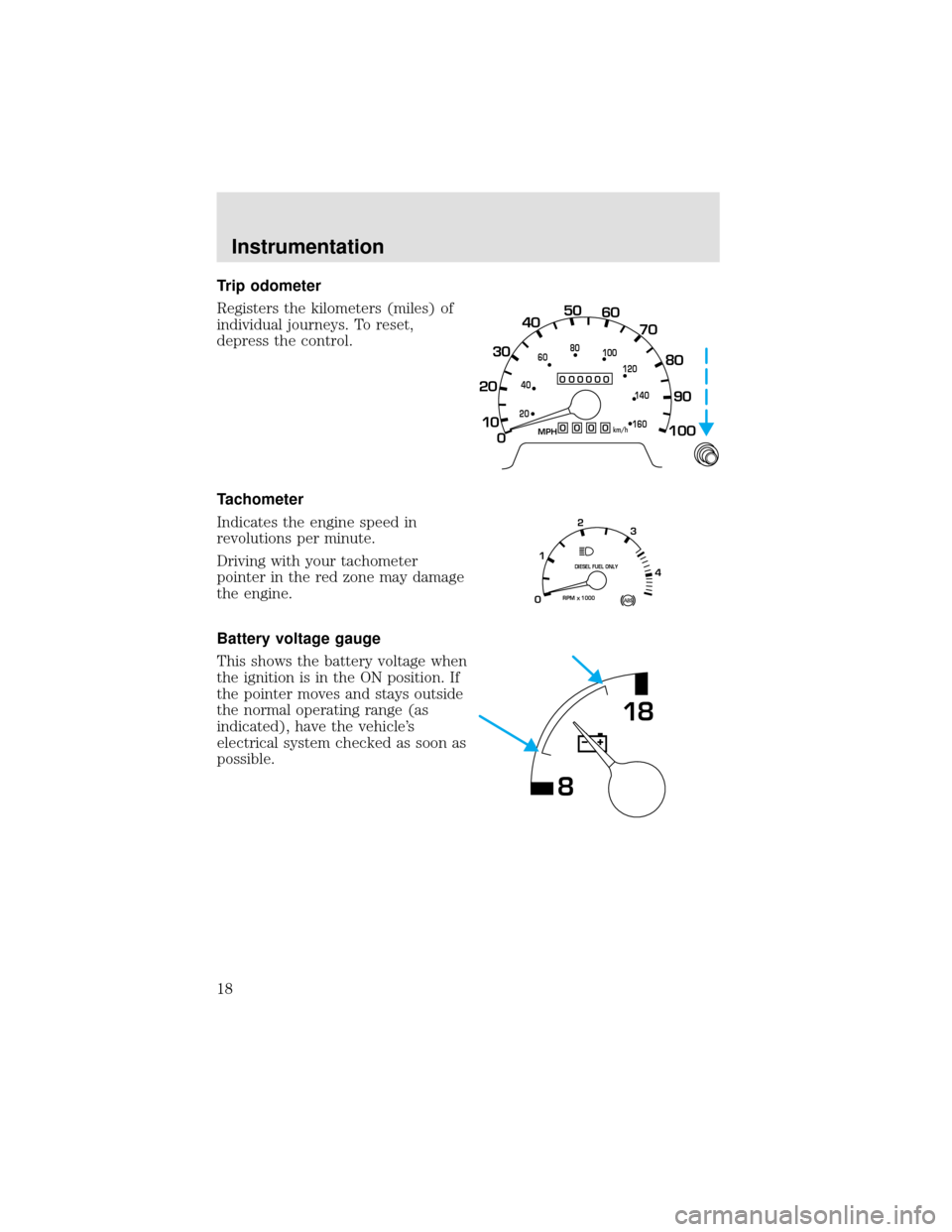
Trip odometer
Registers the kilometers (miles) of
individual journeys. To reset,
depress the control.
Tachometer
Indicates the engine speed in
revolutions per minute.
Driving with your tachometer
pointer in the red zone may damage
the engine.
Battery voltage gauge
This shows the battery voltage when
the ignition is in the ON position. If
the pointer moves and stays outside
the normal operating range (as
indicated), have the vehicle’s
electrical system checked as soon as
possible.
0
000000000
MPH
20km/h
406080
100
120
140
160
0
10 20304050
60
70
80
90
100
RPM1000
DIESEL FUEL ONLY
X012
3
4
818
Instrumentation
18
Page 80 of 208
Excessive full throttle operation below peak torque RPM will shorten
engine life to overhaul and can cause serious engine damage. Operation
of the engine below peak torque RPM can occur during gear shifting due
to difference of gear ratios.
COLD WEATHER STARTING
Perform the following to assure efficient starting in cold weather:
•Use the proper grade oil for your climate. Refer to your engine
operator’s manual for proper grade oil.
•Test the battery more frequently to assure ample power for starting.
•All electrical connections should be tight and in good condition to
prevent losses through loose or corroded connections.
USING THE ENGINE BLOCK HEATER (IF EQUIPPED)
An engine block heater warms the engine coolant, which improves
starting, warms up the engine faster and allows the heater-defroster
system to respond quickly. Use of an engine block heater is strongly
recommended if you live in a region where temperatures reach -23°C
(-10°F) or below.
For best results, plug the heater in at least three hours before starting the
vehicle. Using the heater for longer than three hours will not harm the
engine, so the heater can be plugged in the night before starting the vehicle.
To prevent electrical shock, do not use your heater with
ungrounded electrical systems or two-pronged (cheater)
adapters.
ENGINE SHUTDOWN SYSTEM (IF EQUIPPED)
This system is designed to help prevent engine damage that could result
from operating the engine during a prolonged period of low engine oil
pressure, high engine coolant temperature or low coolant level. If any of
these conditions occur, a warning light will illuminate and a chime will
sound warning the operator that the engine will shutdown in 30 seconds.
This is to allow time for the operator to move the vehicle off the road. If
additional time is required, the engine can be restarted and run each
time for approximately 30 seconds.
Do not attempt to use this restarting feature to drive the vehicle, serious
engine damage could result.
Starting
80
Page 119 of 208
Power distribution box
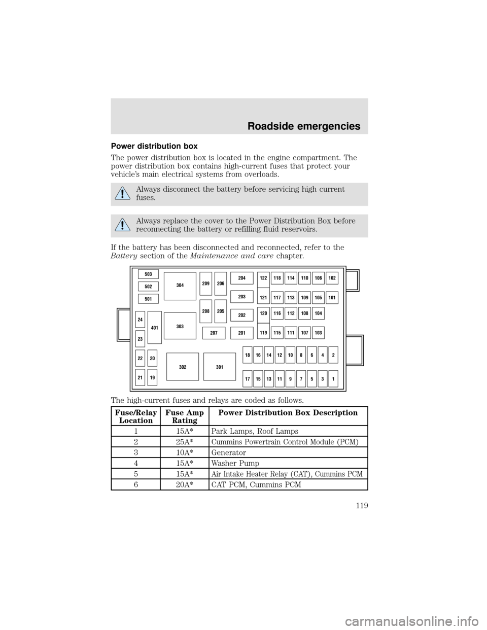
The power distribution box is located in the engine compartment. The
power distribution box contains high-current fuses that protect your
vehicle’s main electrical systems from overloads.
Always disconnect the battery before servicing high current
fuses.
Always replace the cover to the Power Distribution Box before
reconnecting the battery or refilling fluid reservoirs.
If the battery has been disconnected and reconnected, refer to the
Batterysection of theMaintenance and carechapter.
The high-current fuses and relays are coded as follows.
Fuse/Relay
LocationFuse Amp
RatingPower Distribution Box Description
1 15A* Park Lamps, Roof Lamps
2 25A*
Cummins Powertrain Control Module (PCM)
3 10A* Generator
4 15A* Washer Pump
5 15A*
Air Intake Heater Relay (CAT), Cummins PCM
6 20A* CAT PCM, Cummins PCM
503
304
303
302301
502
501
207201
202
203
204122118114110106102
121117113109105101
120116112108104
119115111107103
24
209206
208
18161412108642
1715131197531
205
23
22
21
401
20
19
Roadside emergencies
119
Page 120 of 208

Fuse/Relay
LocationFuse Amp
RatingPower Distribution Box Description
7 15A* Stop Lamps
8 25A* C AT Fuel Heater
9—Not Used
10 15A* Shift Modulator (Allison AT trans only)
11 20A* Allison MD Trans
12—Not Used
13—Not Used
14—Not Used
15 7.5A*
Body Builder Prep (Hydraulic Vehicles Only)
16—Not Used
17—Not Used
18—Not Used
19—Not Used
20—Not Used
21 10A* GEM (Hydraulic Vehicles Only)
22—Not Used
23—Not Used
24—Not Used
101 40A** ABS (Air Only)
102 20A** Body Builder Prep Run Feed
103 50A** Ignition Switch (JB fuses 8, 9, 11, 19, 20,
22, 23, 24, 25, 29, 30, 31)
104 20A** Power Point
105 20A** Power Door Locks
106 30A** Headlamps
107 50A** Junction Box Battery Feed (fuses 1, 2, 3, 4,
12, 13, 14, 15)
108 40A** Cummins Fuel Heater
109 40A** Power Windows
110—Not Used
111 30A** Body Builder Prep
Roadside emergencies
120
Page 122 of 208
JUMP STARTING YOUR VEHICLE
The gases around the battery can explode if exposed to flames,
sparks, or lit cigarettes. An explosion could result in injury or
vehicle damage.
Do not push start your vehicle. You could damage the catalytic
converter.
Batteries contain sulfuric acid which burns skin, eyes, and
clothing.
Preparing your vehicle
Also see the label on the battery.
1. Use only a 12–volt supply to start your vehicle. If you connect your
battery to a 24–volt power supply you can damage your starter, ignition
system and other electrical components. Do not attach the jumper cables
to the glow plug relay as this could severely damage the glow plugs,
injector driver module and PCM.
2. Do not disconnect the battery of the disabled vehicle as this could
damage the vehicle’s electrical system.
3. Park the booster vehicle close to the disabled vehicle making sure
theydo nottouch. Set the parking brake on both vehicles and stay clear
of the engine cooling fan and other moving parts.
4. Check all battery terminals and remove any excessive corrosion before
you attach the battery cables.
5. Turn the heater fan on in both vehicles to protect any electrical
surges. Turn all other accessories off.
Roadside emergencies
122
Page 123 of 208
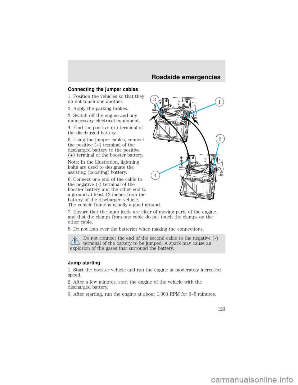
Connecting the jumper cables
1. Position the vehicles so that they
do not touch one another.
2. Apply the parking brakes.
3. Switch off the engine and any
unnecessary electrical equipment.
4. Find the positive (+) terminal of
the discharged battery.
5. Using the jumper cables, connect
the positive (+) terminal of the
discharged battery to the positive
(+) terminal of the booster battery.
Note: In the illustration, lightning
bolts are used to designate the
assisting (boosting) battery.
6. Connect one end of the cable to
the negative (-) terminal of the
booster battery and the other end to
a ground at least 12 inches from the
battery of the discharged vehicle.
The vehicle frame is usually a good ground.
7. Ensure that the jump leads are clear of moving parts of the engine,
and that the clamps from one cable do not touch the clamps on the
other cable.
8. Do not lean over the batteries when making the connections.
Do not connect the end of the second cable to the negative (-)
terminal of the battery to be jumped. A spark may cause an
explosion of the gases that surround the battery.
Jump starting
1. Start the booster vehicle and run the engine at moderately increased
speed.
2. After a few minutes, start the engine of the vehicle with the
discharged battery.
3. After starting, run the engine at about 1,000 RPM for 3–5 minutes.
13
2
4
Roadside emergencies
123
Page 124 of 208
Do not operate the starter longer than 30 seconds. Wait at least
two minutes between starting attempts to allow the starter to
cool. If the engine does not start after several attempts, call for
road service.
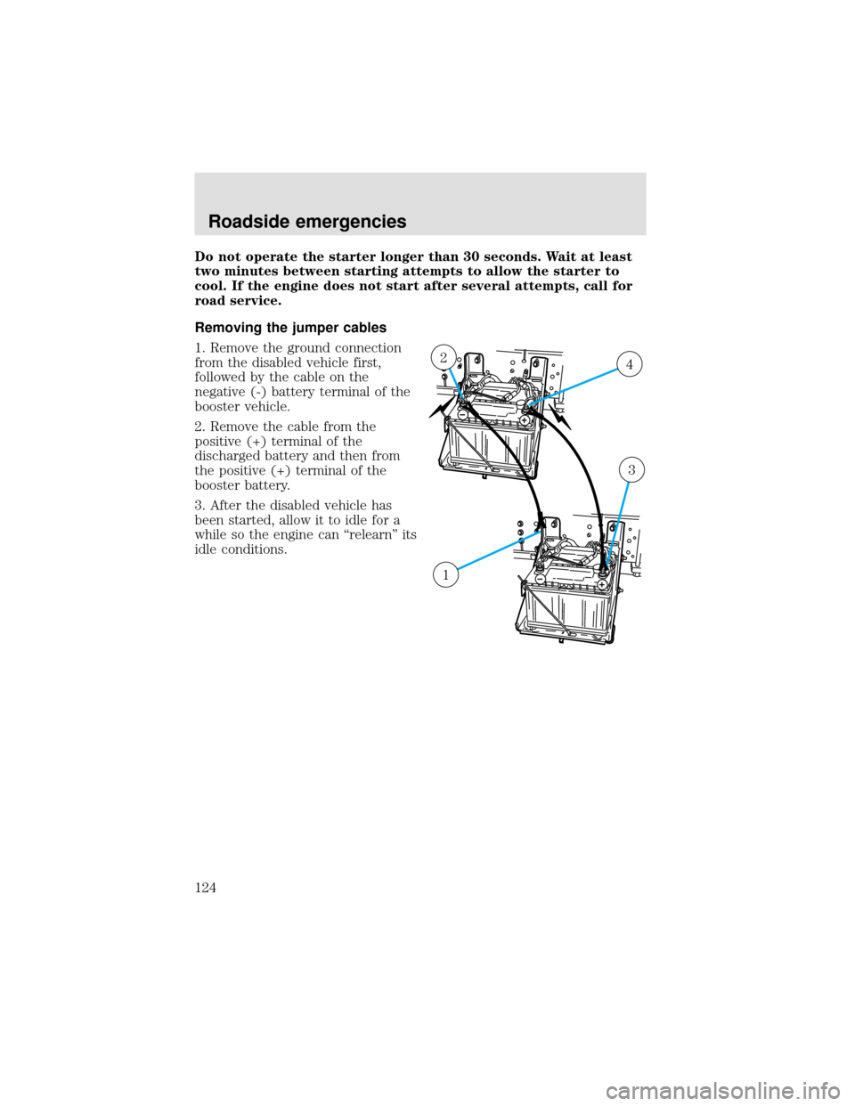
Removing the jumper cables
1. Remove the ground connection
from the disabled vehicle first,
followed by the cable on the
negative (-) battery terminal of the
booster vehicle.
2. Remove the cable from the
positive (+) terminal of the
discharged battery and then from
the positive (+) terminal of the
booster battery.
3. After the disabled vehicle has
been started, allow it to idle for a
while so the engine can“relearn”its
idle conditions.
42
3
1
Roadside emergencies
124
Page 140 of 208
3. Set the parking brake and shift into N (Neutral) (automatic
transmission) or 1 (First) (manual transmission) and turn the engine off.
4. Clean any dirt from around the rear axle filler and drain plugs.
5. Remove the filler and drain plugs and drain the lubricant into a
suitable container. Dispose all used automotive fluids in a responsible
manner following your local authorized standards.
6. Clean and install the drain plug securely.
7. Add enough lubricant through the filler plug opening so that the
lubricant level is up to the bottom of the opening.
8. Clean and install the filler plug securely.
BATTERY
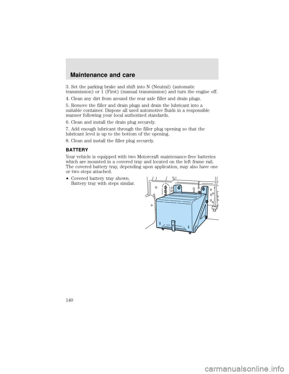
Your vehicle is equipped with two Motorcraft maintenance-free batteries
which are mounted in a covered tray and located on the left frame rail.
The covered battery tray, depending upon application, may also have one
or two steps attached.
•Covered battery tray shown.
Battery tray with steps similar.
Maintenance and care
140
Page 141 of 208
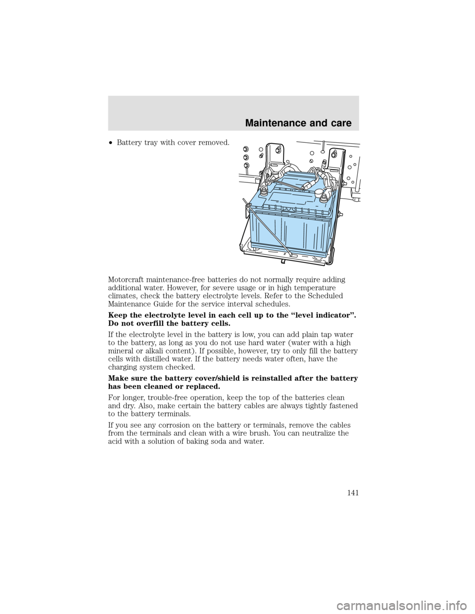
•Battery tray with cover removed.
Motorcraft maintenance-free batteries do not normally require adding
additional water. However, for severe usage or in high temperature
climates, check the battery electrolyte levels. Refer to the Scheduled
Maintenance Guide for the service interval schedules.
Keep the electrolyte level in each cell up to the “level indicator”.
Do not overfill the battery cells.
If the electrolyte level in the battery is low, you can add plain tap water
to the battery, as long as you do not use hard water (water with a high
mineral or alkali content). If possible, however, try to only fill the battery
cells with distilled water. If the battery needs water often, have the
charging system checked.
Make sure the battery cover/shield is reinstalled after the battery
has been cleaned or replaced.
For longer, trouble-free operation, keep the top of the batteries clean
and dry. Also, make certain the battery cables are always tightly fastened
to the battery terminals.
If you see any corrosion on the battery or terminals, remove the cables
from the terminals and clean with a wire brush. You can neutralize the
acid with a solution of baking soda and water.
Maintenance and care
141