clutch FORD F750 2002 10.G User Guide
[x] Cancel search | Manufacturer: FORD, Model Year: 2002, Model line: F750, Model: FORD F750 2002 10.GPages: 256, PDF Size: 1.75 MB
Page 147 of 256

Axle downshift
In order to shift from HIGH to LOW,
²Push the axle shift control down.
²Release the accelerator (while pushing the axle shift control down).
²Depress the accelerator to resume driving.
Split upshift
A split upshift is when there is an axle downshift with a transmission
upshift.
A split upshift can be done as follows:
²Depress the clutch.
²Shift the transmission, while keeping the axle shift control up in
HIGH.
²After the transmission lever movement has ended, push the axle shift
control down.
²Release the clutch.
²Depress the accelerator.
When split shifting, the axle shift control must stay UP in the
HIGH range until after any transmission lever movement.
Split downshift
A split downshift is when there is an axle upshift with a transmission
downshift.
A split downshift can be done as follows:
²Pull the axle shift control up.
²Depress the clutch.
²Shift the transmission, while keeping the axle shift control up in
HIGH.
²Release the clutch.
Split shift sequence
123 4 567891011
1st 1st 2nd 2nd 3rd 3rd 4th 4th 5th 6th 6th
LO HI LO HI LO HI LO HI LO LO HI
Driving
147
Page 153 of 256
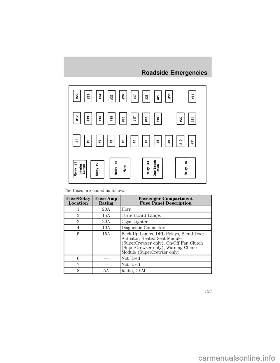
The fuses are coded as follows:
Fuse/Relay
LocationFuse Amp
RatingPassenger Compartment
Fuse Panel Description
1 20A Horn
2 15A Turn/Hazard Lamps
3 20A Cigar Lighter
4 10A Diagnostic Connectors
5 15A Back-Up Lamps, DRL Relays, Blend Door
Actuator, Heated Seat Module
(SuperCrewzer only), On/Off Fan Clutch
(SuperCrewzer only), Warning Chime
Module (SuperCrewzer only)
6 Ð Not Used
7 Ð Not Used
8 5A Radio, GEM
Relay #1
Relay #2
Relay #3
Horn
Relay #4
Relay #5 One Touch
Down Interior
Lamps#1
#12#22
#2
#3
#4
#5
#6
#7
#8
#9
#10
#11#13
#23
#14
#15
#16
#17#24
#25
#26
#27
#18
#28
#19
#29
#20
#21#30
#31
Roadside Emergencies
153
Page 155 of 256

Fuse/Relay
LocationFuse Amp
RatingPassenger Compartment
Fuse Panel Description
28 10A Left Low Beam Headlamp
29 10A Cluster, GEM, 7.3L Power Stroke PCM
(clutch switch input), APCM (7.3L Power
Stroke only), Overhead Console
(SuperCrewzer only), Keyless Entry
Module (SuperCrewzer only), Traxx (Fuel)
Module (SuperCrewzer only)
30 30A 7.3L Power Stroke PCM Diode, 7.3L Power
Stroke Fuel Heater
31 15A Allison MD Transmission, Neutral Start
Relay and PCM (7.3L Power Stroke only)
Relay 1 Ð Interior Lamps
Relay 2 Ð Not Used
Relay 3 Ð Horn
Relay 4 Ð One Touch Down
Relay 5 Ð Not Used
Power distribution box
The power distribution box is located in the engine compartment. The
power distribution box contains high-current fuses that protect your
vehicle's main electrical systems from overloads.
Always disconnect the battery before servicing high current
fuses.
Always replace the cover to the power distribution box before
reconnecting the battery or refilling fluid reservoirs
If the battery has been disconnected and reconnected, refer to the
Batterysection of theMaintenance and specificationschapter.
Roadside Emergencies
155
Page 195 of 256
If you drive in extremely hot climates:
²It is still necessary to maintain the coolant concentration
above 40%.
²NEVER decrease the coolant concentration below 40%.
²Decreased engine coolant concentrations below 40% will
decrease the corrosion protection characteristics of the engine
coolant and may cause engine damage.
²Decreased engine coolant concentrations below 40% will
decrease the freeze protection characteristics of the engine
coolant and may cause engine damage.
²Refer to the chart on the coolant container to ensure the
coolant concentration in your vehicle will provide adequate
protection at the temperatures in which you drive.
Vehicles driven year-round in non-extreme climates should use a 50/50
mixture of engine coolant and distilled water for optimum cooling system
and engine protection.
Coolant conditioner (liquid)
For engines filled with green-colored Motorcraft Premium Engine
Coolant, a supplemental coolant additive FW-16 meeting Ford
specification ESN-M99B169±A has been added to the coolant in this
engine.
This additive aids in the prevention of rust and scale buildup on the
internal parts of the cooling system. Prevention of rust and scale buildup
allows for proper dissipation of heat generated by combustion.
See the ªscheduled maintenance guideº for recommended intervals.
Fan clutches
Your vehicle's cooling system is equipped with a viscous variable speed
fan clutch.
²The fan clutch helps control cooling, increase performance, improve
fuel economy and reduce noise.
²The fan clutch is controlled by bimetallic spring sensors. Do not
tamper with these sensors as this may change their calibration or keep
the fan clutch from operating at all.
Maintenance and Specifications
195
Page 206 of 256
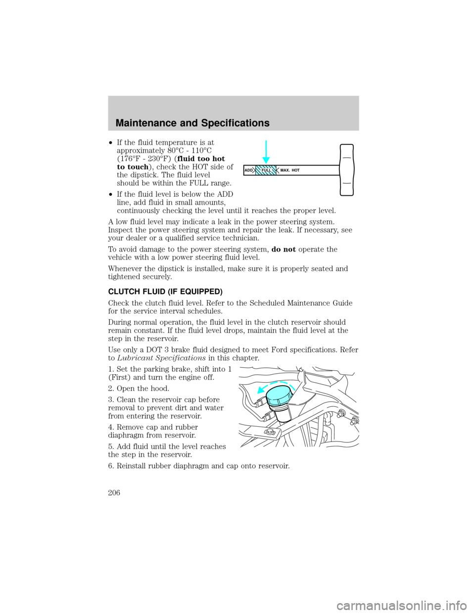
²If the fluid temperature is at
approximately 80ÉC - 110ÉC
(176ÉF - 230ÉF) (fluid too hot
to touch), check the HOT side of
the dipstick. The fluid level
should be within the FULL range.
²If the fluid level is below the ADD
line, add fluid in small amounts,
continuously checking the level until it reaches the proper level.
A low fluid level may indicate a leak in the power steering system.
Inspect the power steering system and repair the leak. If necessary, see
your dealer or a qualified service technician.
To avoid damage to the power steering system,do notoperate the
vehicle with a low power steering fluid level.
Whenever the dipstick is installed, make sure it is properly seated and
tightened securely.
CLUTCH FLUID (IF EQUIPPED)
Check the clutch fluid level. Refer to the Scheduled Maintenance Guide
for the service interval schedules.
During normal operation, the fluid level in the clutch reservoir should
remain constant. If the fluid level drops, maintain the fluid level at the
step in the reservoir.
Use only a DOT 3 brake fluid designed to meet Ford specifications. Refer
toLubricant Specificationsin this chapter.
1. Set the parking brake, shift into 1
(First) and turn the engine off.
2. Open the hood.
3. Clean the reservoir cap before
removal to prevent dirt and water
from entering the reservoir.
4. Remove cap and rubber
diaphragm from reservoir.
5. Add fluid until the level reaches
the step in the reservoir.
6. Reinstall rubber diaphragm and cap onto reservoir.
ADD MAX. HOTFULL
Maintenance and Specifications
206
Page 207 of 256

Clutch (if equipped)Ðlinkage lubrication
Lubricate the clutch linkage using the following procedure. Refer to the
Scheduled Maintenance Guide for the service interval schedules.
Use a grease which meets Ford specifications. Refer toLubricant
Specificationsin this chapter.
1. Set the parking brake, shift into 1 (First) and turn the engine off.
2. Remove the inspection cover from the clutch housing.
²Transmission and clutch
removed for clarity.
3. With a grease gun, lubricate the clutch release bearing (at one
location) and the clutch release shaft (at two locations) using the grease
fittings provided.
4. Lubricate clutch release wear pads at the two locations where they
contact the clutch release bearing using a brush or similar tool.
5. Install the inspection cover onto the clutch housing.
Maintenance and Specifications
207
Page 222 of 256
REAR AXLE REFILL CAPACITIES
Make and model Approximate capacity
Rockwell RS-17-144116.6L (35 pints)
Rockwell RS-17-1451, 216.6L (35 pints)
Rockwell RS-21-1451, 216.6L (35 pints)
Rockwell RS-23-1601, 218.9L (40 pints)
1Quantities listed are approximate. Fill axle until the lubricant level is at
bottom of filler hole, with vehicle on level ground.
2If hubs have been removed, add an additional 0.75 liter (1.6 pints) of
axle lubricant. Add lubricant through the axle vent.
FUEL TANK CAPACITIES
Type Approximate capacity
Single tank 246.09L (65 gallons)
Dual tank 492.18L (130 gallons)
LUBRICANT SPECIFICATIONS
Item Ford Part NameFord Part
NumberFord
Specification
Brake and
clutch fluid
(if equipped)Motorcraft High
Performance DOT
3 Motor Vehicle
Brake FluidPM-1 ESA-M6C25-A
and DOT 3
Body hinges,
hood hinges
and latches.Multi-Purpose
GreaseXGÐ4 or
F5AZ-19G209-AAESR-M1C159-A
Lock cylinders Penetrating
LubricantXL-1 N/A
Maintenance and Specifications
222
Page 223 of 256

Item Ford Part NameFord Part
NumberFord
Specification
Front axle
spindle pins,
steering
linkage, front
and rear
spring shackle
pins, steering
column
U-joints,
steering shaft
slip yoke and
universal joint,
steering shaft
pillow block
bearing,
clutch linkage
fittings.Premium Long
Life GreaseXG-1-C or
XG-1-KESA-M1C75-B
Maintenance and Specifications
223
Page 224 of 256
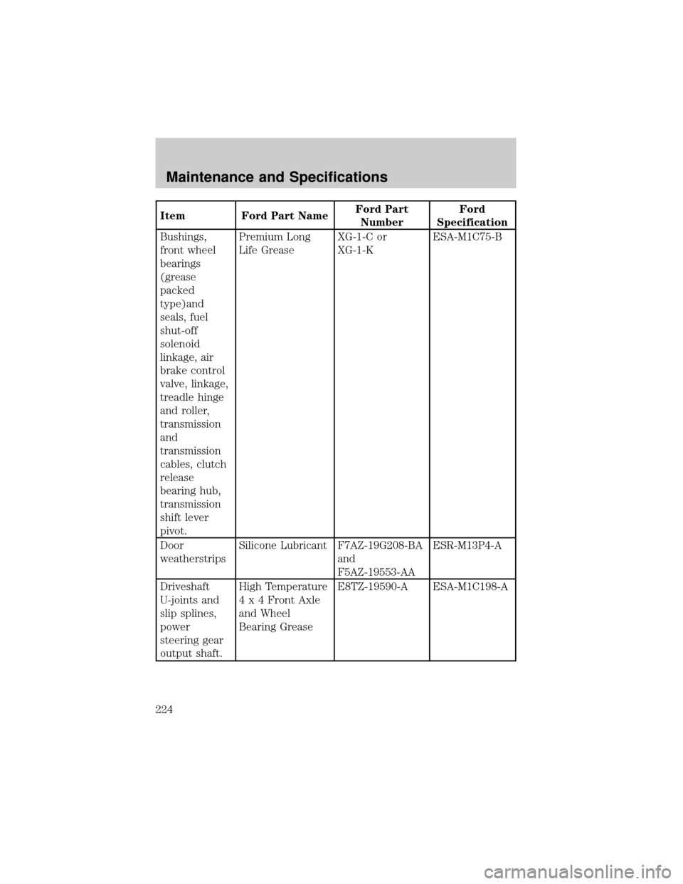
Item Ford Part NameFord Part
NumberFord
Specification
Bushings,
front wheel
bearings
(grease
packed
type)and
seals, fuel
shut-off
solenoid
linkage, air
brake control
valve, linkage,
treadle hinge
and roller,
transmission
and
transmission
cables, clutch
release
bearing hub,
transmission
shift lever
pivot.Premium Long
Life GreaseXG-1-C or
XG-1-KESA-M1C75-B
Door
weatherstripsSilicone Lubricant F7AZ-19G208-BA
and
F5AZ-19553-AAESR-M13P4-A
Driveshaft
U-joints and
slip splines,
power
steering gear
output shaft.High Temperature
4 x 4 Front Axle
and Wheel
Bearing GreaseE8TZ-19590-A ESA-M1C198-A
Maintenance and Specifications
224
Page 225 of 256

Item Ford Part NameFord Part
NumberFord
Specification
Spring leaves,
transmission
linkage pivots,
brake and
clutch pedal
pivots and
clevises,
transmatic
detent stop,
starter motor.Motorcraft SAE
10W30 Super
Duty Motor OilXO-10W30-QSD WSS-M2C171-C
Automatic
transmissionRefer to the Allison Automatic Transmission Operator's
manual.
Rear axle and
front wheel
bearings (oil
filled)
1
Motorcraft SAE
80W-90 Premium
Rear Axle
LubricantXY-80W90-QL WSP-M2C197-A
Motorcraft SAE
75W-140 High
Performance Rear
Axle LubricantXY-75W-140±QL WSL-M2C192-A
Manual
transmission
1Motor oil SAE 50
(above -18ÉC
[0ÉF])2WSE-M2C908-A
Motorcraft SAE 30
Super Duty Motor
oil (below -18ÉC
[0ÉF])XO-30-QSD
3WSS-M2C171-C
Engine oil
-7.3L Power
Stroke
engine
1, 4
Motorcraft Super
Duty Motor oilXO-15W40-QSD3
XO-10W30-QSD3WSS-M2C171-C
Motorcraft SAE
0W-30 Super All
Season Motor oil
(synthetic)XO-0W30-LAS
Maintenance and Specifications
225