trailer FORD F750 2006 11.G Owner's Manual
[x] Cancel search | Manufacturer: FORD, Model Year: 2006, Model line: F750, Model: FORD F750 2006 11.GPages: 272, PDF Size: 1.86 MB
Page 149 of 272
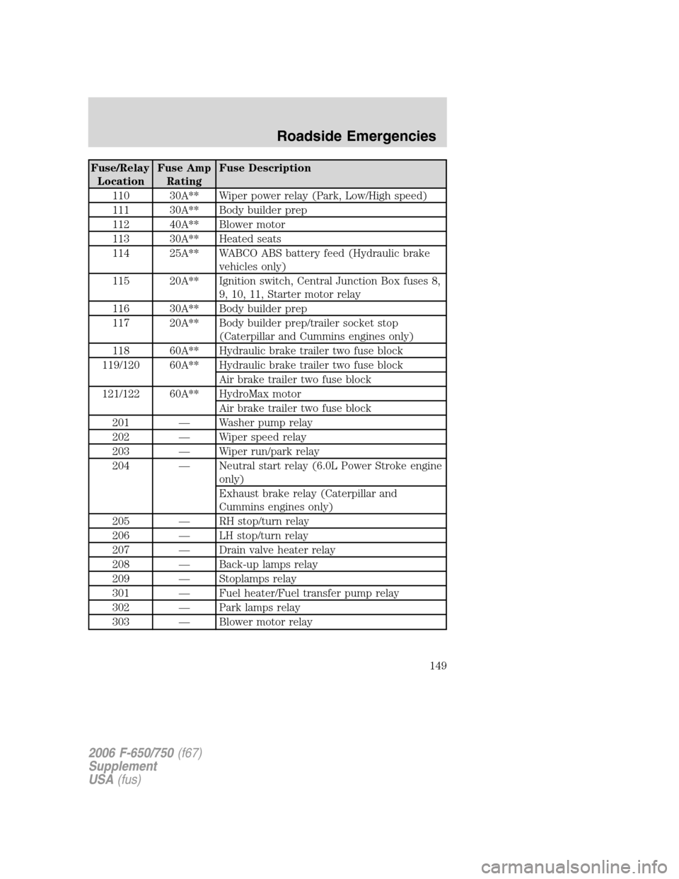
Fuse/Relay
LocationFuse Amp
RatingFuse Description
110 30A** Wiper power relay (Park, Low/High speed)
111 30A** Body builder prep
112 40A** Blower motor
113 30A** Heated seats
114 25A** WABCO ABS battery feed (Hydraulic brake
vehicles only)
115 20A** Ignition switch, Central Junction Box fuses 8,
9, 10, 11, Starter motor relay
116 30A** Body builder prep
117 20A** Body builder prep/trailer socket stop
(Caterpillar and Cummins engines only)
118 60A** Hydraulic brake trailer two fuse block
119/120 60A** Hydraulic brake trailer two fuse block
Air brake trailer two fuse block
121/122 60A** HydroMax motor
Air brake trailer two fuse block
201 — Washer pump relay
202 — Wiper speed relay
203 — Wiper run/park relay
204 — Neutral start relay (6.0L Power Stroke engine
only)
Exhaust brake relay (Caterpillar and
Cummins engines only)
205 — RH stop/turn relay
206 — LH stop/turn relay
207 — Drain valve heater relay
208 — Back-up lamps relay
209 — Stoplamps relay
301 — Fuel heater/Fuel transfer pump relay
302 — Park lamps relay
303 — Blower motor relay
2006 F-650/750(f67)
Supplement
USA(fus)
Roadside Emergencies
149
Page 150 of 272
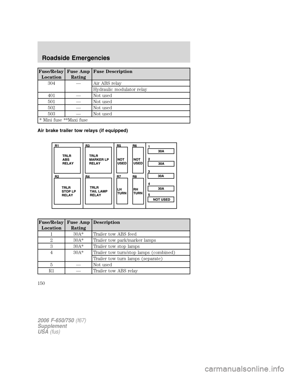
Fuse/Relay
LocationFuse Amp
RatingFuse Description
304 — Air ABS relay
Hydraulic modulator relay
401 — Not used
501 — Not used
502 — Not used
503 — Not used
* Mini fuse **Maxi fuse
Air brake trailer tow relays (if equipped)
Fuse/Relay
LocationFuse Amp
RatingDescription
1 30A* Trailer tow ABS feed
2 30A* Trailer tow park/marker lamps
3 30A* Trailer tow stop lamps
4 30A* Trailer tow turn/stop lamps (combined)
Trailer tow turn lamps (separate)
5 — Not used
R1 — Trailer tow ABS relay
2006 F-650/750(f67)
Supplement
USA(fus)
Roadside Emergencies
150
Page 151 of 272
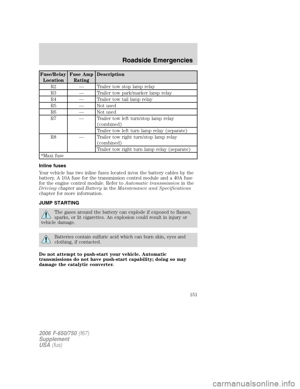
Fuse/Relay
LocationFuse Amp
RatingDescription
R2 — Trailer tow stop lamp relay
R3 — Trailer tow park/marker lamp relay
R4 — Trailer tow tail lamp relay
R5 — Not used
R6 — Not used
R7 — Trailer tow left turn/stop lamp relay
(combined)
Trailer tow left turn lamp relay (separate)
R8 — Trailer tow right turn/stop lamp relay
(combined)
Trailer tow right turn lamp relay (separate)
*Maxi fuse
Inline fuses
Your vehicle has two inline fuses located in/on the battery cables by the
battery. A 10A fuse for the transmission control module and a 40A fuse
for the engine control module. Refer toAutomatic transmissionin the
Drivingchapter andBatteryin theMaintenance and Specifications
chapter for more information.
JUMP STARTING
The gases around the battery can explode if exposed to flames,
sparks, or lit cigarettes. An explosion could result in injury or
vehicle damage.
Batteries contain sulfuric acid which can burn skin, eyes and
clothing, if contacted.
Do not attempt to push-start your vehicle. Automatic
transmissions do not have push-start capability; doing so may
damage the catalytic converter.
2006 F-650/750(f67)
Supplement
USA(fus)
Roadside Emergencies
151
Page 172 of 272
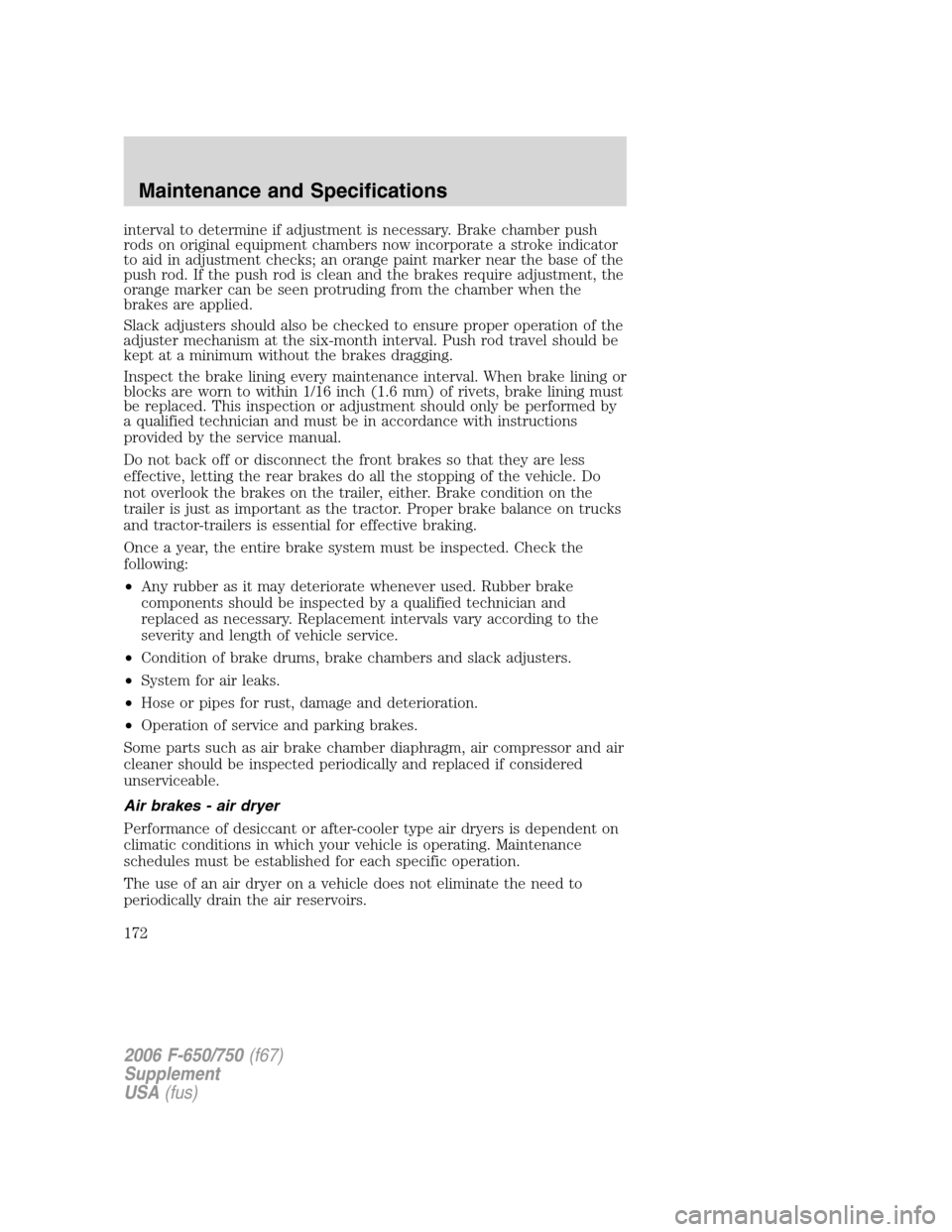
interval to determine if adjustment is necessary. Brake chamber push
rods on original equipment chambers now incorporate a stroke indicator
to aid in adjustment checks; an orange paint marker near the base of the
push rod. If the push rod is clean and the brakes require adjustment, the
orange marker can be seen protruding from the chamber when the
brakes are applied.
Slack adjusters should also be checked to ensure proper operation of the
adjuster mechanism at the six-month interval. Push rod travel should be
kept at a minimum without the brakes dragging.
Inspect the brake lining every maintenance interval. When brake lining or
blocks are worn to within 1/16 inch (1.6 mm) of rivets, brake lining must
be replaced. This inspection or adjustment should only be performed by
a qualified technician and must be in accordance with instructions
provided by the service manual.
Do not back off or disconnect the front brakes so that they are less
effective, letting the rear brakes do all the stopping of the vehicle. Do
not overlook the brakes on the trailer, either. Brake condition on the
trailer is just as important as the tractor. Proper brake balance on trucks
and tractor-trailers is essential for effective braking.
Once a year, the entire brake system must be inspected. Check the
following:
•Any rubber as it may deteriorate whenever used. Rubber brake
components should be inspected by a qualified technician and
replaced as necessary. Replacement intervals vary according to the
severity and length of vehicle service.
•Condition of brake drums, brake chambers and slack adjusters.
•System for air leaks.
•Hose or pipes for rust, damage and deterioration.
•Operation of service and parking brakes.
Some parts such as air brake chamber diaphragm, air compressor and air
cleaner should be inspected periodically and replaced if considered
unserviceable.
Air brakes - air dryer
Performance of desiccant or after-cooler type air dryers is dependent on
climatic conditions in which your vehicle is operating. Maintenance
schedules must be established for each specific operation.
The use of an air dryer on a vehicle does not eliminate the need to
periodically drain the air reservoirs.
2006 F-650/750(f67)
Supplement
USA(fus)
Maintenance and Specifications
172
Page 180 of 272
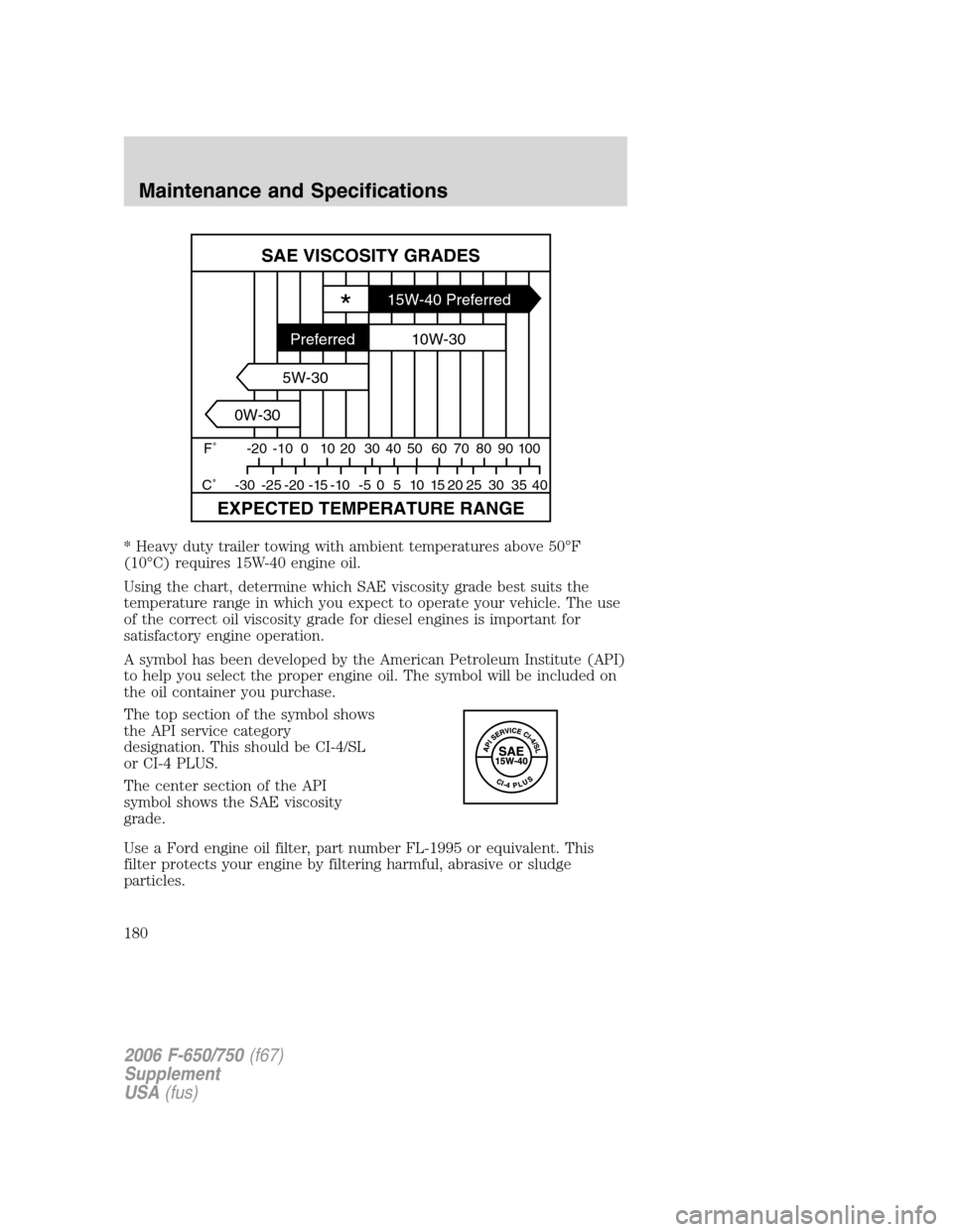
* Heavy duty trailer towing with ambient temperatures above 50°F
(10°C) requires 15W-40 engine oil.
Using the chart, determine which SAE viscosity grade best suits the
temperature range in which you expect to operate your vehicle. The use
of the correct oil viscosity grade for diesel engines is important for
satisfactory engine operation.
A symbol has been developed by the American Petroleum Institute (API)
to help you select the proper engine oil. The symbol will be included on
the oil container you purchase.
The top section of the symbol shows
the API service category
designation. This should be CI-4/SL
or CI-4 PLUS.
The center section of the API
symbol shows the SAE viscosity
grade.
Use a Ford engine oil filter, part number FL-1995 or equivalent. This
filter protects your engine by filtering harmful, abrasive or sludge
particles.
SAE VISCOSITY GRADES
EXPECTED TEMPERATURE RANGE
F˚ -20 -10 0 10 20 30 40
40 35 30 25 20 15 10 5 0 -5 -10 -15 -20 -25 -30 C˚50 60 70 80 90 100
*15W-40 Preferred
10W-30
5W-30
0W-30Preferred
2006 F-650/750(f67)
Supplement
USA(fus)
Maintenance and Specifications
180