stop start FORD F750 2007 11.G Owner's Manual
[x] Cancel search | Manufacturer: FORD, Model Year: 2007, Model line: F750, Model: FORD F750 2007 11.GPages: 280, PDF Size: 1.93 MB
Page 146 of 280
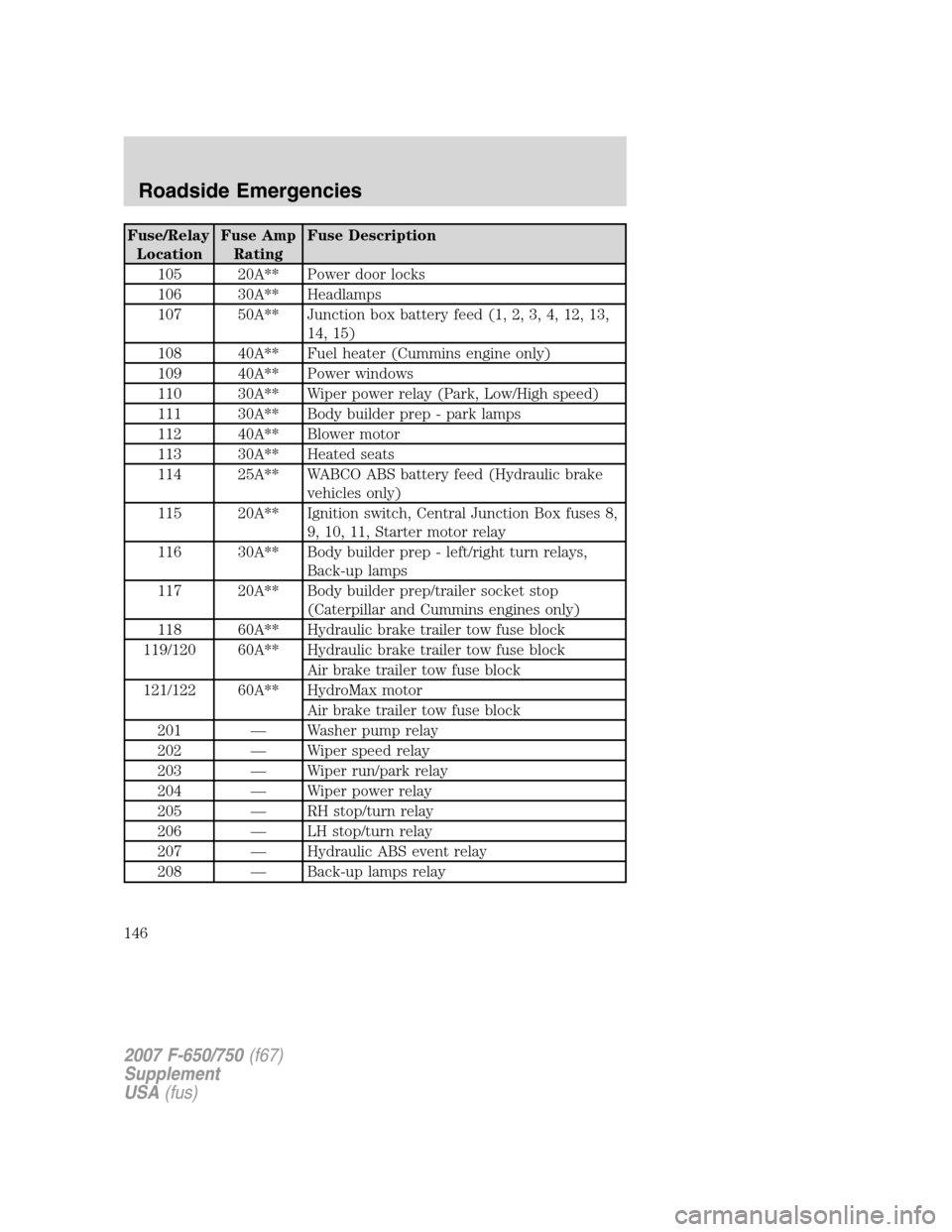
Fuse/Relay
LocationFuse Amp
RatingFuse Description
105 20A** Power door locks
106 30A** Headlamps
107 50A** Junction box battery feed (1, 2, 3, 4, 12, 13,
14, 15)
108 40A** Fuel heater (Cummins engine only)
109 40A** Power windows
110 30A** Wiper power relay (Park, Low/High speed)
111 30A** Body builder prep - park lamps
112 40A** Blower motor
113 30A** Heated seats
114 25A** WABCO ABS battery feed (Hydraulic brake
vehicles only)
115 20A** Ignition switch, Central Junction Box fuses 8,
9, 10, 11, Starter motor relay
116 30A** Body builder prep - left/right turn relays,
Back-up lamps
117 20A** Body builder prep/trailer socket stop
(Caterpillar and Cummins engines only)
118 60A** Hydraulic brake trailer tow fuse block
119/120 60A** Hydraulic brake trailer tow fuse block
Air brake trailer tow fuse block
121/122 60A** HydroMax motor
Air brake trailer tow fuse block
201 — Washer pump relay
202 — Wiper speed relay
203 — Wiper run/park relay
204 — Wiper power relay
205 — RH stop/turn relay
206 — LH stop/turn relay
207 — Hydraulic ABS event relay
208 — Back-up lamps relay
2007 F-650/750(f67)
Supplement
USA(fus)
Roadside Emergencies
146
Page 148 of 280
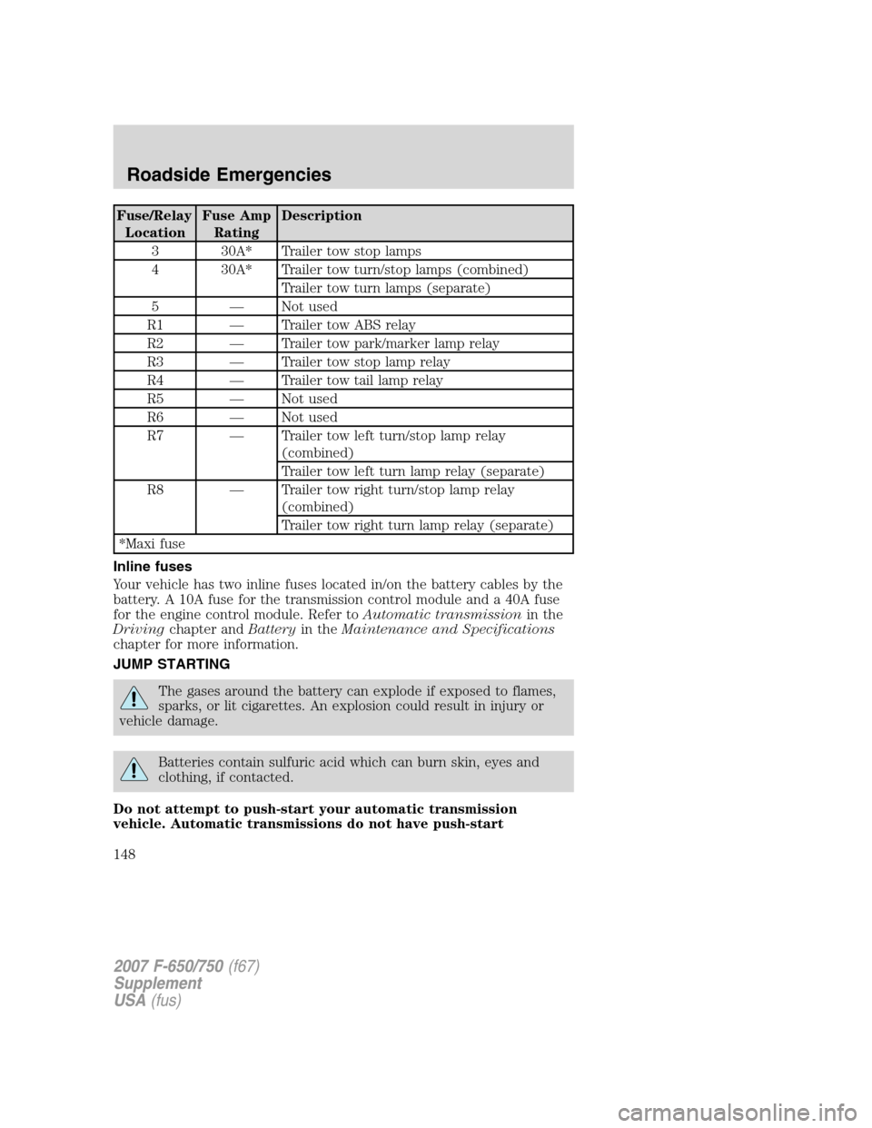
Fuse/Relay
LocationFuse Amp
RatingDescription
3 30A* Trailer tow stop lamps
4 30A* Trailer tow turn/stop lamps (combined)
Trailer tow turn lamps (separate)
5 — Not used
R1 — Trailer tow ABS relay
R2 — Trailer tow park/marker lamp relay
R3 — Trailer tow stop lamp relay
R4 — Trailer tow tail lamp relay
R5 — Not used
R6 — Not used
R7 — Trailer tow left turn/stop lamp relay
(combined)
Trailer tow left turn lamp relay (separate)
R8 — Trailer tow right turn/stop lamp relay
(combined)
Trailer tow right turn lamp relay (separate)
*Maxi fuse
Inline fuses
Your vehicle has two inline fuses located in/on the battery cables by the
battery. A 10A fuse for the transmission control module and a 40A fuse
for the engine control module. Refer toAutomatic transmissionin the
Drivingchapter andBatteryin theMaintenance and Specifications
chapter for more information.
JUMP STARTING
The gases around the battery can explode if exposed to flames,
sparks, or lit cigarettes. An explosion could result in injury or
vehicle damage.
Batteries contain sulfuric acid which can burn skin, eyes and
clothing, if contacted.
Do not attempt to push-start your automatic transmission
vehicle. Automatic transmissions do not have push-start
2007 F-650/750(f67)
Supplement
USA(fus)
Roadside Emergencies
148
Page 182 of 280
If the engine coolant has not been checked at the recommended interval,
the engine coolant reservoir may become low or empty. If the reservoir is
low or empty, add engine coolant to the reservoir. Refer toAdding
engine coolantin this chapter.
Note:Automotive fluids are not interchangeable; do not use engine
coolant, antifreeze or windshield washer fluid outside of its specified
function and vehicle location.
Adding engine coolant - 6.0L Power Stroke
Note:The engine coolant reservoir requires air space for expansion
volume. The proper fill level is identified on the reservoir; do not overfill
the reservoir.
Note:If the coolant should get extremely low and the engine very hot,
let the engine cool for approximately 15 minutes before adding coolant.
After the engine has cooled, start the engine and add coolant slowly.
Adding coolant to a hot engine may crack the cylinder head or
crankcase. Never use only water to fill the cooling system.
When adding coolant, make sure it is a 50/50 mixture of engine coolant
and distilled water. Add the mixture to the coolant reservoir,when the
engine is cool, until the appropriate fill level is obtained.
Do not add engine coolant when the engine is hot. Steam and
scalding liquids released from a hot cooling system can burn you
badly. Also, you can be burned if you spill coolant on hot engine parts.
Do not put engine coolant in the windshield washer fluid
container. If sprayed on the windshield, engine coolant could
make it difficult to see through the windshield.
The cooling system in your vehicle is filled with yellow-colored
Motorcraft Premium Gold Engine Coolant meeting Ford Specification
WSS-M97B51–A1.
Note:Add the coolant type originally equipped in your vehicle.
•Add Motorcraft Premium Gold Engine Coolant, VC-7–B
(yellow-colored).
Note:Use of Motorcraft Cooling System Stop Leak Pellets, VC-6, may
darken the color of Motorcraft Premium Gold Engine Coolant from
yellow to golden tan.
2007 F-650/750(f67)
Supplement
USA(fus)
Maintenance and Specifications
182
Page 186 of 280
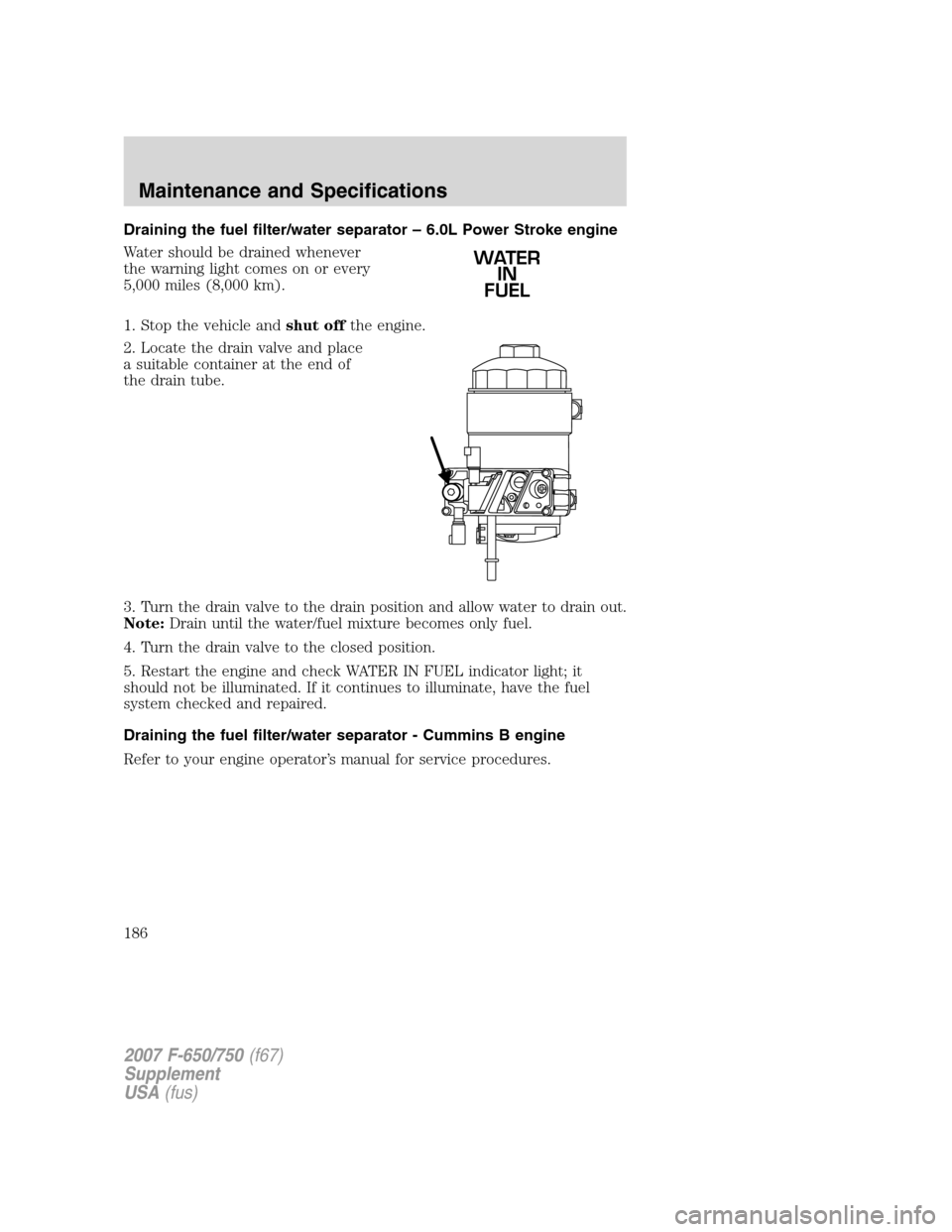
Draining the fuel filter/water separator – 6.0L Power Stroke engine
Water should be drained whenever
the warning light comes on or every
5,000 miles (8,000 km).
1. Stop the vehicle andshut offthe engine.
2. Locate the drain valve and place
a suitable container at the end of
the drain tube.
3. Turn the drain valve to the drain position and allow water to drain out.
Note:Drain until the water/fuel mixture becomes only fuel.
4. Turn the drain valve to the closed position.
5. Restart the engine and check WATER IN FUEL indicator light; it
should not be illuminated. If it continues to illuminate, have the fuel
system checked and repaired.
Draining the fuel filter/water separator - Cummins B engine
Refer to your engine operator’s manual for service procedures.
WATER
IN
FUEL
2007 F-650/750(f67)
Supplement
USA(fus)
Maintenance and Specifications
186
Page 191 of 280
Many of the world’s automakers approved the World-wide Fuel Charter
that recommends diesel fuel specifications to provide improved
performance and emission control system protection for your vehicle.
Diesel fuel that meet the World-wide Fuel Charter should be used when
available. Ask your fuel supplier about fuel that meet the World-Wide
Fuel Charter.
Running out of fuel
Avoid running out of fuel as this will allow air to enter the fuel system,
which will make restarting the vehicle difficult.
If you have run out of fuel:
•If your vehicle is equipped with dual fuel tanks,add at least 4–5
gallons (15–19 liters) of fuel to each tank before attempting to restart
the engine.
•If your vehicle is equipped with a Caterpillar engine,the fuel
system must be primed before attempting to restart the engine. Refer
to the engine operator’s manual for instructions on priming the engine.
•Use caution not to overheat and damage the starterby cranking
the engine for an excessive period of time. You may need to crank the
engine for a longer time than normal. If the engine fails to start in 30
seconds, turn the ignition to the OFF position and wait for two
minutes before cranking the engine again.
•Any remaining trapped air will self-purge from the fuel system once
the engine starts running.
•The engine may run rough and produce white smoke while air is in
the fuel system. This is normal and should stop after a short period of
time.
FUEL CONSUMPTION IMPROVEMENT MEASURES
There are two important factors you can control to improve fuel
economy: the mechanical condition of your vehicle and how you drive it.
A properly maintained vehicle will deliver better performance than a
neglected vehicle. Always follow your maintenance schedule to keep your
vehicle in top operating condition.
Also, your driving habits have a significant influence on use of fuel. By
following these suggestions, you can stretch your fuel use:
•Avoid changes in speed as much as possible.
•Anticipate changing traffic conditions. Sudden stops and fast
acceleration waste fuel.
2007 F-650/750(f67)
Supplement
USA(fus)
Maintenance and Specifications
191
Page 203 of 280
Air suspension U-bolt checks and re-torquing procedures
1. Inspect the threads of the U-bolt and nut for rust and debris. Clean
the threads if contaminated.
2. Using a torque wrench, determine if any nuts can be turned with a
force below the specified torque.
3. Using the lowest discovered torqued nut as a starting point, retighten
the nuts using the sequence listed underAir suspension U-bolt and
U-bolt nut installation.
Air suspension U-bolt and U-bolt nut installation
1. Inspect the threads of the U-bolt and nut for rust and debris. Clean
the threads if contaminated.
2. Install the U-bolts and nuts and torque the nuts to 15 ft. lb. (20 N•m),
using a diagonal pattern.
3. Re-torque the nuts to 100 ft. lb. (136 N•m), using a diagonal pattern.
4. Re-torque the nuts to 200 ft. lb. (271 N•m), using a diagonal pattern.
5. Re-torque the nuts to 400 ft. lb. (542 N•m), using a diagonal pattern.
(For vehicles equipped with 14ACC, 14 ADN and 14ADP axles, do not
use Step 6.)
6. Re-torque the nuts to 425 ft. lb (576 N•m), using a diagonal pattern.
(For vehicles equipped with 14ACC, 14 ADN and 14ADP axles.)
7. Use the same diagonal pattern with each U-bolt nut re-torque.
Spring U-bolt checks
Check U-bolt nuts and re-torque every 36,000 miles (58,000 km) after
initial 1,000 miles (1,600 km) re-torque. The U-bolt and nut threads and
seats should be cleaned and lubricated to ensure peak condition when
re-torqued.
PROPELLER SHAFT
At the regular lubrication interval, check the universal joints for any
evidence of wear or looseness. Should propeller shaft vibrations occur,
stop the vehicle immediately to avoid possible hazardous consequences
or damage to other components.
2007 F-650/750(f67)
Supplement
USA(fus)
Maintenance and Specifications
203
Page 242 of 280
Maintenance Operation Frequency - Observation
Inspect the automatic slack
adjuster functionInsufficient power shown in loaded
practice stop.
Check the operation of the brakes,
the clutch, and the steering
(1),(2)Vehicle handling qualities not up to
par.
Inspect the vehicle for missing,
damaged, or mislocated noise
shieldsExcessive noise emanates from
under the cab or engine
compartment.
Check the engine performance
and the engine governorExcessive engine noise.
Inspect the fan, the fan shroud,
and the fan clutchEngine overheats, fan runs at high
speed constantly, excessive fan
noise, or fan wobble due to worn
bearings.
Check for operation of ABS
warning lampAt each engine start up.
Inspect the entire exhaust system
(including inlet pipe, muffler,
outlet pipe and all exhaust clamps
and fasteners) for holes, leakage,
breakage, looseness and corrosive
damageExcessive noise or the smell of
fumes is experienced.
Inspect the engine air induction
system (including the air ducts
and the air filter) for loose fitting,
damaged or missing componentsExcessive noise emanates from the
engine compartment.
Inspect the tires and check the air
pressure
(3)Poor steering, wandering or
excessive tire wear.
Balance the wheels and the tires Vibration or abnormal tire wear
indicates imbalance.
Check the front end alignment
(3)Poor steering, wandering or
excessive tire wear.
Check the transmission and
engine mountings
(2)Hard shifting or excessive
vibration.
2007 F-650/750(f67)
Supplement
USA(fus)
Scheduled Maintenance Guide
242