coolant FORD F750 2013 12.G Owners Manual
[x] Cancel search | Manufacturer: FORD, Model Year: 2013, Model line: F750, Model: FORD F750 2013 12.GPages: 378, PDF Size: 3.82 MB
Page 5 of 378
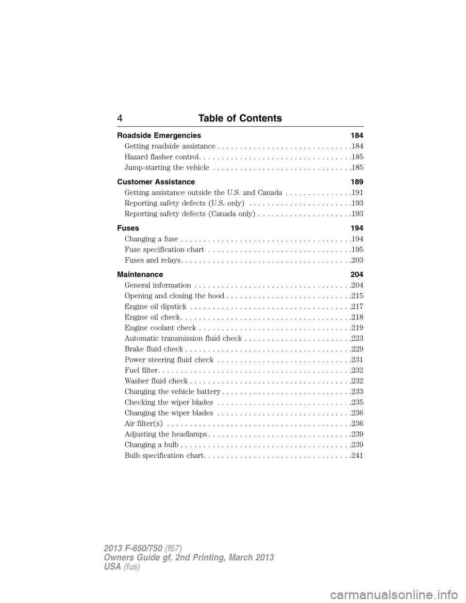
Roadside Emergencies 184
Getting roadside assistance..............................184
Hazard flasher control..................................185
Jump-starting the vehicle...............................185
Customer Assistance 189
Getting assistance outside the U.S. and Canada...............191
Reporting safety defects (U.S. only).......................193
Reporting safety defects (Canada only).....................193
Fuses 194
Changing a fuse......................................194
Fuse specification chart................................195
Fuses and relays......................................203
Maintenance 204
General information...................................204
Opening and closing the hood............................215
Engine oil dipstick....................................217
Engine oil check......................................218
Engine coolant check..................................219
Automatic transmission fluid check........................223
Brake fluid check.....................................229
Power steering fluid check..............................231
Fuel filter...........................................232
Washer fluid check....................................232
Changing the vehicle battery.............................233
Checking the wiper blades..............................235
Changing the wiper blades..............................236
Air filter(s).........................................236
Adjusting the headlamps................................239
Changing a bulb......................................239
Bulb specification chart.................................241
4Table of Contents
2013 F-650/750(f67)
Owners Guide gf, 2nd Printing, March 2013
USA(fus)
Page 9 of 378
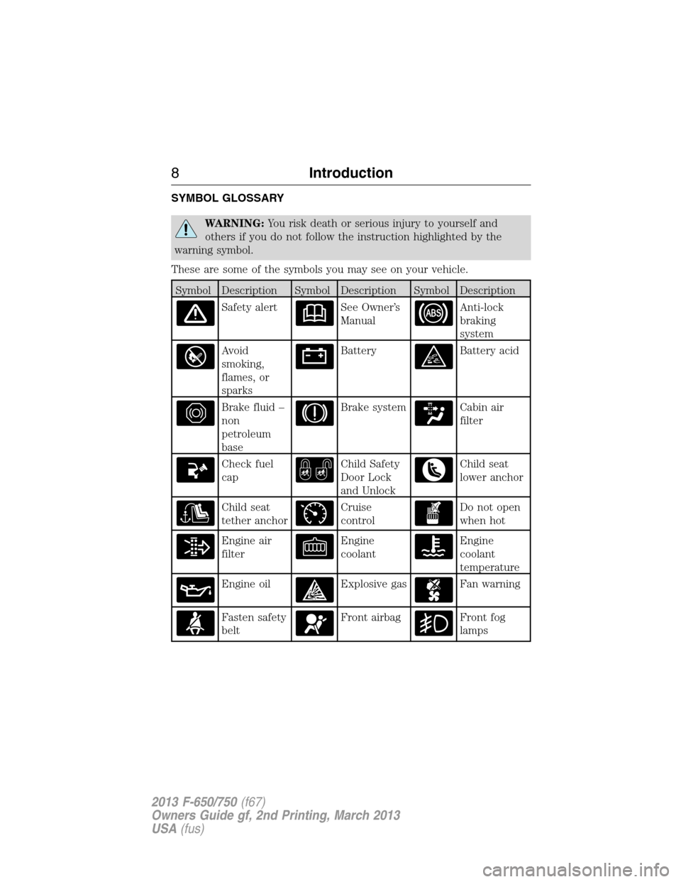
SYMBOL GLOSSARY
WARNING:You risk death or serious injury to yourself and
others if you do not follow the instruction highlighted by the
warning symbol.
These are some of the symbols you may see on your vehicle.
Symbol Description Symbol Description Symbol Description
Safety alertSee Owner’s
ManualAnti-lock
braking
system
Avoid
smoking,
flames, or
sparksBatteryBattery acid
Brake fluid –
non
petroleum
baseBrake systemCabin air
filter
Check fuel
capChild Safety
Door Lock
and UnlockChild seat
lower anchor
Child seat
tether anchorCruise
controlDo not open
when hot
Engine air
filterEngine
coolantEngine
coolant
temperature
Engine oilExplosive gasFan warning
Fasten safety
beltFront airbagFront fog
lamps
8Introduction
2013 F-650/750(f67)
Owners Guide gf, 2nd Printing, March 2013
USA(fus)
Page 15 of 378
VEHICLE INSPECTION INFORMATION
To be sure your vehicle is ready to operate, conduct a pre-trip inspection
at the beginning of each work period. Follow the steps listed in this
section to ensure a proper vehicle inspection procedure. The pages in
this section may be produced locally and used on a regular basis.
WARNING:Exercise great caution when working on a vehicle
equipped with an automatic fan clutch. The fan starts in motion
only after the engine coolant reaches a predetermined temperature or
the refrigerant pressure (if equipped with air conditioning) reaches a
predetermined setting. The fan starts at this point with no advance
warning. Never reach near, or permit objects to protrude into, the fan
blade radius while the engine is running as this could result in vehicle
damage, personal injury or death.
WARNING:Do not operate the vehicle if any suspension
conditions listed in the following charts are evident. Loss of
steering or suspension could result in property damage, personal injury
or death.
WARNING:If a wheel must be changed, obtain expert tire
service help. Mounting and un-mounting of tires should only be
performed by a qualified technician using necessary safety procedures
and equipment, otherwise the result could be property damage,
personal injury or death.
Note:Always make sure the parking brake is applied before starting the
engine.
14Vehicle Inspection Guide
2013 F-650/750(f67)
Owners Guide gf, 2nd Printing, March 2013
USA(fus)
Page 16 of 378
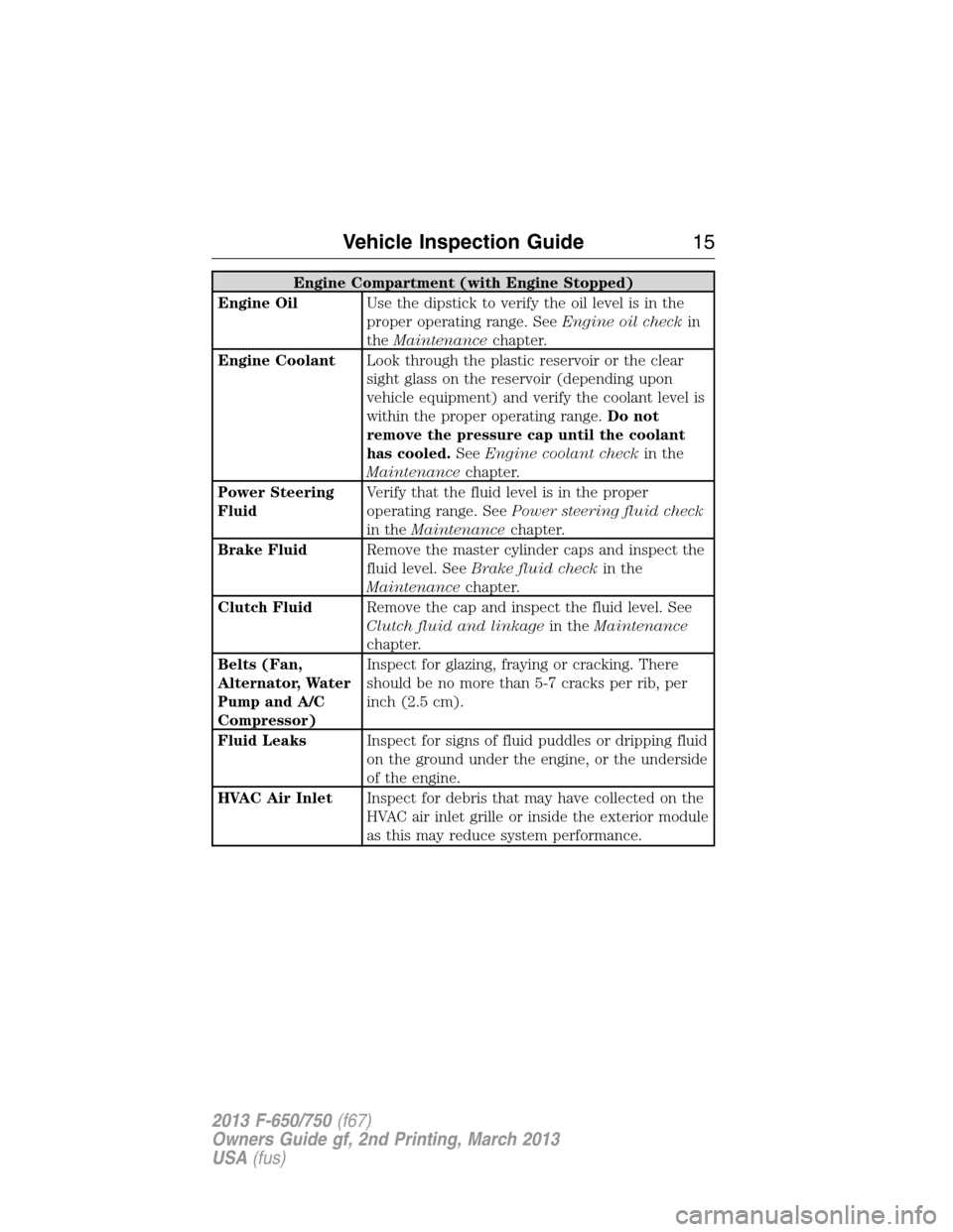
Engine Compartment (with Engine Stopped)
Engine OilUse the dipstick to verify the oil level is in the
proper operating range. SeeEngine oil checkin
theMaintenancechapter.
Engine CoolantLook through the plastic reservoir or the clear
sight glass on the reservoir (depending upon
vehicle equipment) and verify the coolant level is
within the proper operating range.Do not
remove the pressure cap until the coolant
has cooled.SeeEngine coolant checkin the
Maintenancechapter.
Power Steering
FluidVerify that the fluid level is in the proper
operating range. SeePower steering fluid check
in theMaintenancechapter.
Brake FluidRemove the master cylinder caps and inspect the
fluid level. SeeBrake fluid checkin the
Maintenancechapter.
Clutch FluidRemove the cap and inspect the fluid level. See
Clutch fluid and linkagein theMaintenance
chapter.
Belts (Fan,
Alternator, Water
Pump and A/C
Compressor)Inspect for glazing, fraying or cracking. There
should be no more than 5-7 cracks per rib, per
inch (2.5 cm).
Fluid LeaksInspect for signs of fluid puddles or dripping fluid
on the ground under the engine, or the underside
of the engine.
HVAC Air InletInspect for debris that may have collected on the
HVAC air inlet grille or inside the exterior module
as this may reduce system performance.
Vehicle Inspection Guide15
2013 F-650/750(f67)
Owners Guide gf, 2nd Printing, March 2013
USA(fus)
Page 65 of 378
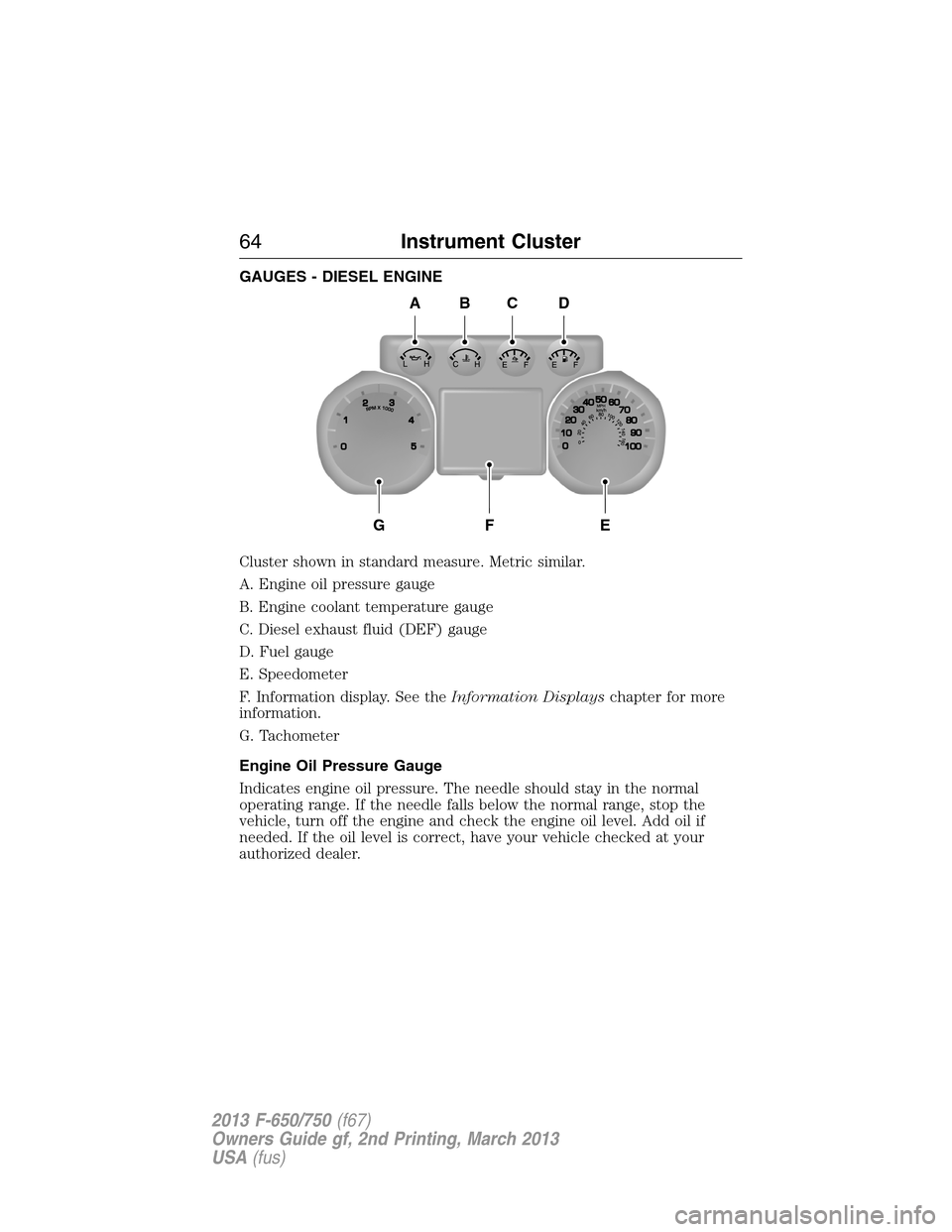
GAUGES - DIESEL ENGINE
Cluster shown in standard measure. Metric similar.
A. Engine oil pressure gauge
B. Engine coolant temperature gauge
C. Diesel exhaust fluid (DEF) gauge
D. Fuel gauge
E. Speedometer
F. Information display. See theInformation Displayschapter for more
information.
G. Tachometer
Engine Oil Pressure Gauge
Indicates engine oil pressure. The needle should stay in the normal
operating range. If the needle falls below the normal range, stop the
vehicle, turn off the engine and check the engine oil level. Add oil if
needed. If the oil level is correct, have your vehicle checked at your
authorized dealer.
A
GFE
BCD
64Instrument Cluster
2013 F-650/750(f67)
Owners Guide gf, 2nd Printing, March 2013
USA(fus)
Page 66 of 378
Engine Coolant Temperature Gauge
Indicates engine coolant temperature. At normal operating temperature,
the level indicator is in the normal range. If the engine coolant
temperature exceeds the normal range, stop the vehicle as soon as safely
possible, switch off the engine and let the engine cool.
WARNING:Never remove the coolant reservoir cap while the
engine is running or hot.
Diesel Exhaust Fluid (DEF) Gauge
Indicates fluid level in DEF tank.
Fuel Gauge
Indicates approximately how much fuel is left in the fuel tank (when the
ignition is on). The fuel gauge may vary slightly when the vehicle is in
motion or on a grade. The fuel icon and arrow indicates which side of
the vehicle the fuel filler door is located.
Information Display
Odometer:Located in the bottom of the information display. Registers
the accumulated distance your vehicle has travelled.
Trip Computer:SeeGeneral informationin theInformation Displays
chapter.
Vehicle Settings and Personalization:SeeGeneral informationin
theInformation Displayschapter.
Instrument Cluster65
2013 F-650/750(f67)
Owners Guide gf, 2nd Printing, March 2013
USA(fus)
Page 67 of 378
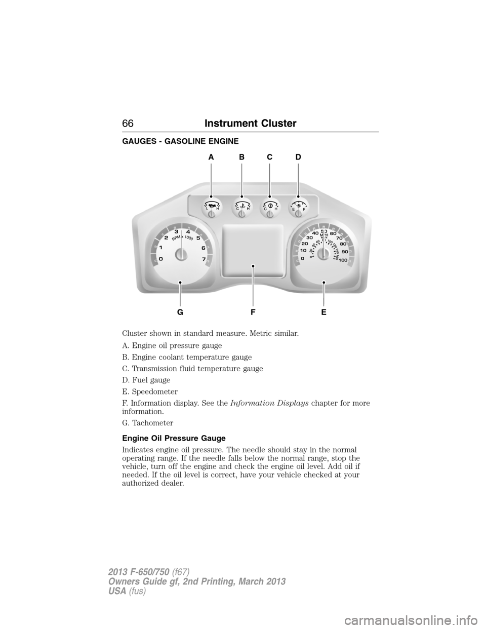
GAUGES - GASOLINE ENGINE
Cluster shown in standard measure. Metric similar.
A. Engine oil pressure gauge
B. Engine coolant temperature gauge
C. Transmission fluid temperature gauge
D. Fuel gauge
E. Speedometer
F. Information display. See theInformation Displayschapter for more
information.
G. Tachometer
Engine Oil Pressure Gauge
Indicates engine oil pressure. The needle should stay in the normal
operating range. If the needle falls below the normal range, stop the
vehicle, turn off the engine and check the engine oil level. Add oil if
needed. If the oil level is correct, have your vehicle checked at your
authorized dealer.
ABCD
GFE
66Instrument Cluster
2013 F-650/750(f67)
Owners Guide gf, 2nd Printing, March 2013
USA(fus)
Page 68 of 378
Engine Coolant Temperature Gauge
Indicates engine coolant temperature. At normal operating temperature,
the level indicator is in the normal range. If the engine coolant
temperature exceeds the normal range, stop the vehicle as soon as safely
possible, switch off the engine and let the engine cool.
WARNING:Never remove the coolant reservoir cap while the
engine is running or hot.
Transmission Fluid Temperature Gauge
Indicates transmission fluid temperature. At normal operating
temperature, the level indicator is in the normal range. If the
transmission fluid temperature exceeds the normal range, stop the
vehicle as soon as safely possible and verify the airflow is not restricted,
such as snow or debris blocking airflow through the grill. Also, higher
than normal operating temperature can be caused by special operation
conditions (i.e., snowplowing, towing or off-road use). Operating the
transmission for extended periods of time with the gauge in the higher
than normal area may cause internal transmission damage. Altering the
severity of the driving conditions is recommended to lower the
transmission temperature into the normal range. If the gauge continues
to show high temperatures, see your authorized dealer.
Fuel Gauge
Indicates approximately how much fuel is left in the fuel tank (when the
ignition is on). The fuel gauge may vary slightly when the vehicle is in
motion or on a grade. The fuel icon and arrow indicates which side of
the vehicle the fuel filler door is located.
Information Display
Odometer:Located in the bottom of the information display. Registers
the accumulated distance your vehicle has travelled.
Trip Computer:SeeGeneral informationin theInformation Displays
chapter.
Vehicle Settings and Personalization:SeeGeneral informationin
theInformation Displayschapter.
Instrument Cluster67
2013 F-650/750(f67)
Owners Guide gf, 2nd Printing, March 2013
USA(fus)
Page 106 of 378
STARTING A DIESEL ENGINE
WARNING:Operation of a diesel engine near flammable vapors
in the air may cause the engine speed to increase uncontrollably
and over speed. If this situation occurs, mechanical damage, fire,
explosion, personal injury or death could result.Turning off the
ignition key does not slow or stop the engine due to uncontrollable
fueling of the engine through flammable vapors being drawn into
the engine air inlet.Operation of components such as starter,
alternator, electric motors, etc. and static electricity could also ignite
flammable vapors.
Do not operate the truck in the possible presence of flammable vapors
unless both a complete hazard analysis is performed and necessary
additional safety processes and/or equipment such as vapor testing, air
intake shutoff devices, ventilation, etc. are utilized. The operator is
responsible for using those processes and/or equipment to ensure that
the diesel engine and all other components on the truck can be
operated safely under the specific conditions and hazards that may be
encountered.
WARNING:If equipped with an air intake heater, DO NOT use
ether or any other starting fluids. The use of starting fluids
(ether) in an engine equipped with an air intake heater could cause an
explosion and result in property damage and/or personal injury.
Switch the ignition on and wait until the glow plug indicator
goes off.
Note:You can only operate the starter for a maximum of 30 seconds at
a time. Allow two minutes before cranking the starter again.
Note:On some engines, the glow plug indicator illuminates after the
engine starts. Allow the engine to idle about three minutes, or until the
engine coolant temperature gauge begins to rise. Maintain idle speed
until the glow plug indicator goes off. Operating the engine at higher
speeds reduces the effectiveness of the air inlet heater.
Note:When starting a cold engine, increase the engine RPM slowly to
make sure adequate lubrication is available to the bearings.
Starting and Stopping the Engine105
2013 F-650/750(f67)
Owners Guide gf, 2nd Printing, March 2013
USA(fus)
Page 111 of 378
The exhaust outlet assembly on your vehicle is a uniquely functioning
device that accompanies the DPF assembly. It is designed to help control
the temperature of the exhaust during the DPF regeneration process.
The inlet holes in the side of the assembly are functional. These holes
allow outside air to be drawn into the outlet assembly. The holes need to
be kept clear of mud and other foreign material to maintain proper
functionality of the system. One way to keep the holes clear is to spray
the outlet assembly with a hose when washing the vehicle. Failure to
keep the functional holes clear of foreign material may result in the holes
becoming blocked or plugged.
SWITCHING OFF A DIESEL ENGINE
Allow the engine to idle for three to five minutes before shutting it
down; the larger the engine, the greater the need for this idling period.
Note:Try to limit engine idle to 10 minutes. Excessive idling reduces
fuel economy.
ENGINE AUTOMATIC SHUTDOWN (IF EQUIPPED)
WARNING:In the event of engine shutdown, make sure the
vehicle is safely off the road and the problem is remedied prior to
returning to the road. Failure to remove the vehicle from the road
could result in an accident, causing serious injury or death.
This feature either illuminates a light in the instrument cluster or sounds
a chime (or both) indicating that the engine is being shut down in the
event of high coolant temperature, low engine oil pressure, high diesel
particulate filter soot loading or low engine coolant level. In the event
any of these conditions exist, the engine automatically shuts down.
If the engine shuts down, it can be restarted and operated for
30 seconds at a time or until the problem is corrected. Do not attempt to
use this restarting feature to drive the vehicle very far as serious engine
damage could result.
11 0Starting and Stopping the Engine
2013 F-650/750(f67)
Owners Guide gf, 2nd Printing, March 2013
USA(fus)