warning lights FORD F750 2015 13.G Owners Manual
[x] Cancel search | Manufacturer: FORD, Model Year: 2015, Model line: F750, Model: FORD F750 2015 13.GPages: 384, PDF Size: 4.95 MB
Page 23 of 384
Trailer
If you are pulling a trailer, perform an inspection of the trailer similar to
that of the tractor. The inspection should follow trailer manufacturer
recommendations and should include at a minimum: general condition,
landing gear, doors, sides, lights, reflectors, suspension, brakes, tires,
wheels, cargo placement, stability and tie-downs.
Transmission
WARNING:If the unit starts in gear and/or the neutral start
switch is not functioning correctly, the vehicle may inadvertently
move which could result in property damage, personal injury or death.
If your vehicle is equipped with an automatic transmission, regularly
inspect the transmission’s neutral start switch. The engine should only
start in positionNorP.
Inspect the transmission fluid level and shift linkage for proper
operation.
22Vehicle Inspection Guide
2015 F-650/750(f67)
Owners Guide gf(ownloose), 1st Printing, December 2013
Canadian_French(fr_can)
Page 90 of 384
(Type 2)
HEATED SEATS (IF EQUIPPED)
WARNING:Persons who are unable to feel pain to the skin
because of advanced age, chronic illness, diabetes, spinal cord
injury, medication, alcohol use, exhaustion, or other physical conditions,
must exercise care when using the seat heater. The seat heater may
cause burns even at low temperatures, especially if used for long
periods of time. Do not place anything on the seat that insulates against
heat, such as a blanket or cushion, because this may cause the seat
heater to overheat. Do not puncture the seat with pins, needles, or
other pointed objects because this may damage the heating element
which may cause the seat heater to overheat. An overheated seat may
cause serious personal injury.
Note:Do not do the following:
•Place heavy objects on the seat.
•Operate the seat heater if water or any other liquid is spilled on the
seat. Allow the seat to dry thoroughly.
•Operate the heated seats unless the engine is running. Doing so could
drain your vehicle’s battery.
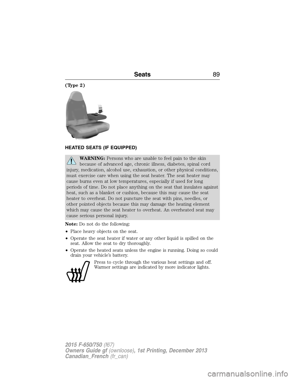
Press to cycle through the various heat settings and off.
Warmer settings are indicated by more indicator lights.
Seats89
2015 F-650/750(f67)
Owners Guide gf(ownloose), 1st Printing, December 2013
Canadian_French(fr_can)
Page 94 of 384
IGNITION SWITCH
Note:When you switch the ignition off and leave your vehicle, do not
leave your key in the ignition. This could discharge your vehicle battery.
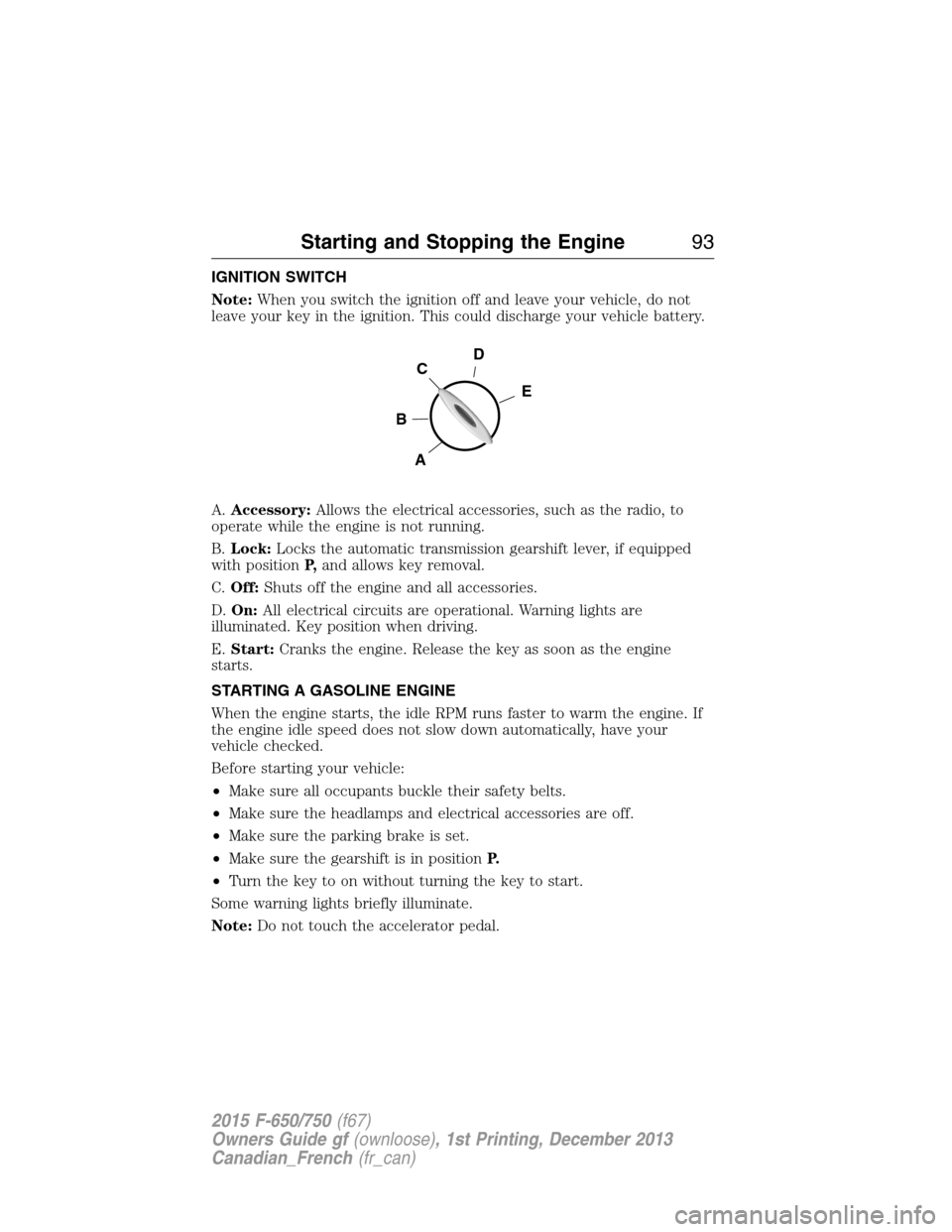
A.Accessory:Allows the electrical accessories, such as the radio, to
operate while the engine is not running.
B.Lock:Locks the automatic transmission gearshift lever, if equipped
with positionP,and allows key removal.
C.Off:Shuts off the engine and all accessories.
D.On:All electrical circuits are operational. Warning lights are
illuminated. Key position when driving.
E.Start:Cranks the engine. Release the key as soon as the engine
starts.
STARTING A GASOLINE ENGINE
When the engine starts, the idle RPM runs faster to warm the engine. If
the engine idle speed does not slow down automatically, have your
vehicle checked.
Before starting your vehicle:
•Make sure all occupants buckle their safety belts.
•Make sure the headlamps and electrical accessories are off.
•Make sure the parking brake is set.
•Make sure the gearshift is in positionP.
•Turn the key to on without turning the key to start.
Some warning lights briefly illuminate.
Note:Do not touch the accelerator pedal.
D
E
C
B
A
Starting and Stopping the Engine93
2015 F-650/750(f67)
Owners Guide gf(ownloose), 1st Printing, December 2013
Canadian_French(fr_can)
Page 111 of 384
Keep a record for at least one month and record the type of driving (city
or highway). This provides an accurate estimate of your vehicle’s fuel
economy under current driving conditions. Additionally, keeping records
during summer and winter shows how temperature impacts fuel
economy. In general, lower temperatures mean lower fuel economy.
SELECTIVE CATALYTIC REDUCTION (SCR) SYSTEM (DIESEL
ENGINE ONLY)
Your vehicle is equipped with a selective catalytic reduction (SCR)
system to help reduce emission levels of oxides of nitrogen from the
exhaust of the diesel engine. The system automatically injects diesel
exhaust fluid (DEF) into the exhaust system to enable proper SCR
function.
Importance of Maintaining the DEF Level
In order for the SCR system to operate properly, you must maintain the
DEF level. Generally, you should fill the DEF tank before the DEF gauge
in the instrument cluster reaches the first low level warning (see
Warning messages and vehicle operations).
The engine control unit monitors the amount of fluid available in the
DEF tank. Failure to maintain an adequate amount of DEF in the system
generates warning messages that appear in the information display and,
unless you refill the DEF tank, leads to a forced reduction of engine
operations.
Warning Messages and Vehicle Operations
The instrument cluster contains a DEF gauge and indicator lights to alert
you to any low DEF level conditions. The indicator lights illuminate if the
DEF gauge level drops below 1 gallon (3.8 liters) in the 5-gallon
(19.0 liters) DEF tank or 2 gallons (7.6 liters) in the 10-gallon
(34.0 liters) DEF tank.
Upon filling the DEF tank after a low-level warning, normal operation
resumes when you restart your vehicle.
11 0Fuel and Refueling
2015 F-650/750(f67)
Owners Guide gf(ownloose), 1st Printing, December 2013
Canadian_French(fr_can)
Page 170 of 384
Safety Chains
Note:Do not attach safety chains to the bumper.
Always connect the trailer’s safety chains to the frame or hook retainers
of your vehicle hitch.
To connect the trailer’s safety chains, cross the chains under the trailer
tongue and allow enough slack for turning tight corners. Do not allow the
chains to drag on the ground.
Trailer Brakes
WARNING:Do not connect a trailer’s hydraulic brake system
directly to your vehicle’s brake system. Your vehicle may not have
enough braking power and your chances of having a crash greatly
increase.
Electric brakes and manual, automatic or surge-type trailer brakes are
safe if you install them properly and adjust them to the manufacturer’s
specifications. The trailer brakes must meet local and federal regulations.
The rating for the tow vehicle’s braking system operation is at
the gross vehicle weight rating, not the gross combined weight
rating.
Trailer Lamps
WARNING:Never connect any trailer lamp wiring to the
vehicle’s tail lamp wiring; this may damage the electrical system
resulting in a fire. Contact an authorized dealer as soon as possible for
assistance in proper trailer tow wiring installation. Additional electrical
equipment may be required.
Trailer lamps are required on most towed vehicles. Make sure all running
lights, brake lights, turn signals and hazard lights are working.
Before Towing a Trailer
Practice turning, stopping and backing up to get the feel of your
vehicle-trailer combination before starting on a trip. When turning, make
wider turns so the trailer wheels clear curbs and other obstacles.
When Towing a Trailer
•Check your hitch, electrical connections and trailer wheel lug nuts
thoroughly after you have traveled 50 miles (80 kilometers).
Towing169
2015 F-650/750(f67)
Owners Guide gf(ownloose), 1st Printing, December 2013
Canadian_French(fr_can)
Page 172 of 384
4. Make sure the coupler release lever is in the locked position.
5. Charge the trailer brake system. Set the trailer brakes, with either
the hand valve or tractor protection valve. Pull against the trailer for
an extra check of proper hook-up. Do not pull hard enough to
damage or strain the equipment.
6. Set the tractor parking brakes and fully raise the trailer landing gear.
See theBrakeschapter for proper operation of the parking brake
and trailer brakes.
7. Check the operation of all trailer lights and correct any lights that
may be faulty.
Un-hook
1. Try to keep the tractor and trailer in a straight line.
2. Apply the parking brakes.
3. Lower the trailer landing gear, making sure it is on solid, level
ground. The weight of the trailer is to be on the landing gear.
4. Block the trailer wheels.
5. Disconnect the brake hoses and light cords. Be sure hoses and cords
are clear.
6. Pull coupler release lever to disengage the fifth wheel jaws.
7. Release the tractor parking brakes.
8. Pull out from the trailer slowly, allowing the landing gear to take the
load gradually.
WRECKER TOWING
WARNING:To reduce the risk of personal injury or property
damage when manually releasing the spring brakes, be sure to
block the wheels so the vehicle cannot move once the brakes are
released.
Note:Make sure to connect your vehicle securely to the tow vehicle and
that the tow vehicle’s parking brakes are set before releasing the disabled
vehicle’s spring brakes.
Before moving the disabled vehicle, check for adequate road clearance of
vehicle components. If possible, unload the disabled vehicle before
towing. This reduces any abnormal load to the vehicle components
resulting from the towing procedures. Before towing, make sure to
release the parking brake fully. You can reset the spring-actuated type
parking brake by recharging the air system with at least 64 psi (441 kPa)
of air. If the brake system does not retain air pressure, then you must
release the spring brakes manually. SeeParking brakein theBrakes
chapter.
Towing171
2015 F-650/750(f67)
Owners Guide gf(ownloose), 1st Printing, December 2013
Canadian_French(fr_can)
Page 195 of 384
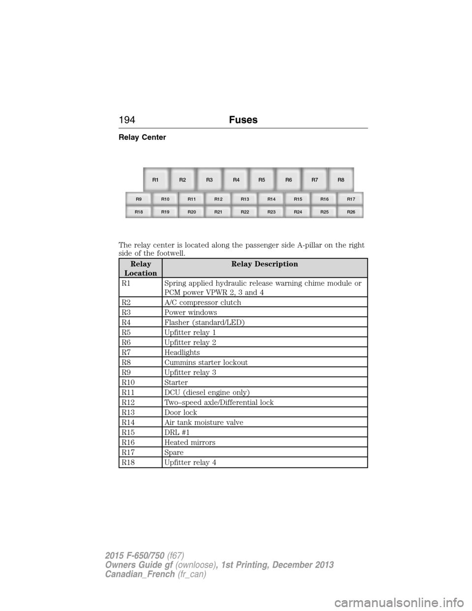
Relay Center
The relay center is located along the passenger side A-pillar on the right
side of the footwell.
Relay
LocationRelay Description
R1 Spring applied hydraulic release warning chime module or
PCM power VPWR 2, 3 and 4
R2 A/C compressor clutch
R3 Power windows
R4 Flasher (standard/LED)
R5 Upfitter relay 1
R6 Upfitter relay 2
R7 Headlights
R8 Cummins starter lockout
R9 Upfitter relay 3
R10 Starter
R11 DCU (diesel engine only)
R12 Two–speed axle/Differential lock
R13 Door lock
R14 Air tank moisture valve
R15 DRL #1
R16 Heated mirrors
R17 Spare
R18 Upfitter relay 4
R1
R9 R10 R11 R12 R13 R14 R15 R16 R17
R18 R19 R20 R21 R22 R23 R24 R25 R26
R2 R3 R4 R5 R6 R7 R8
194Fuses
2015 F-650/750(f67)
Owners Guide gf(ownloose), 1st Printing, December 2013
Canadian_French(fr_can)
Page 196 of 384
Relay
LocationRelay Description
R19 Shift interlock/EPRNDL display
R20 Selective Catalyst Reduction (SCR) system (NOx) (diesel
engine only)
R21 Run
R22 Door unlock
R23 ABS warning indicator
R24 DRL #2
R25 Park lights
R26 Spare
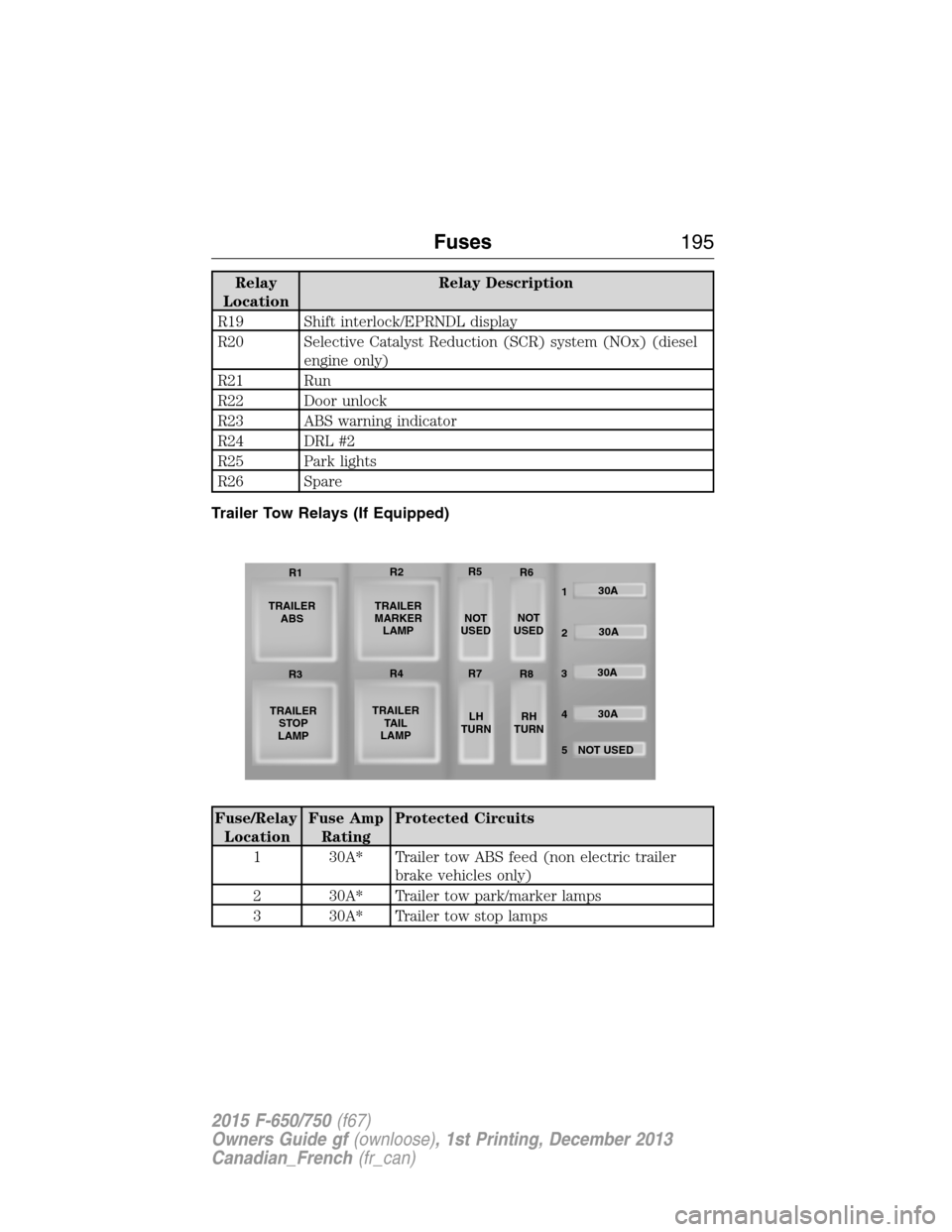
Trailer Tow Relays (If Equipped)
Fuse/Relay
LocationFuse Amp
RatingProtected Circuits
1 30A* Trailer tow ABS feed (non electric trailer
brake vehicles only)
2 30A* Trailer tow park/marker lamps
3 30A* Trailer tow stop lamps
TRAILER
ABS
TRAILER
STOP
LAMPTRAILER
MARKER
LAMP
TRAILER
TA I L
LAMPNOT
USEDNOT
USED
LH
TURNRH
TURN30A
30A
30A
30A
NOT USED
5 4 32 1 R1R2R5
R6
R3R4R7
R8
Fuses195
2015 F-650/750(f67)
Owners Guide gf(ownloose), 1st Printing, December 2013
Canadian_French(fr_can)
Page 199 of 384
Quality service parts are available through an authorized dealer. If dealer
parts are not used, make sure the replacement parts are of equivalent
quality.
WARNING:The use of inferior parts can adversely affect the
quality and reliability of your vehicle which, in turn, can result in
property damage, personal injury or death.
To avoid damage to your vehicle’s electrical components before electric
welding:
•Disconnect both battery cables.
•Attach the welder ground cable as close as possible to the part being
welded.
•We recommend temporarily removing the component if welding close
to an electrical component.
Follow the checks and services in theScheduled Maintenancechapter.
Have an authorized dealer or service center inspect your vehicle at least
once a year. Remember that regular maintenance and inspections usually
prevent serious problems from developing later.
If the owner or operator of the vehicle is a skilled technician and intends
on performing the vehicle maintenance and service, he is strongly urged
to purchase a service manual.
Electrical System
Periodically inspect electrical connectors on the outside of the cab and
on the engine and frame for corrosion and tightness. Exposed terminals,
such as the fuel sender, cranking motor, alternator and feed-through
studs, should be cleaned and re-coated with a lubricant sealing grease
such as Motorcraft Silicone Brake Caliper Grease and Dielectric
Compound XG-3, or equivalent. This should include the ground cable
connector for batteries, engine and cab as well as the jump-starting stud.
Accessory Feed Connections
Vehicle electrical systems are complex and often include powertrain
components, such as engine and transmission controls, instrument panels
and ABS. While most systems operate on battery voltage (12 volts),
some systems can be as high as 90 volts or as low as five volts. See the
Electrical Circuit Diagram Manuals,available from your vehicle’s
manufacturer, to make sure that any extra body lights and accessory
connections to circuits are both appropriate and not overloaded. Do not
make modifications to any vehicle control system without first contacting
an authorized dealer.
198Maintenance
2015 F-650/750(f67)
Owners Guide gf(ownloose), 1st Printing, December 2013
Canadian_French(fr_can)
Page 382 of 384
Lights, warning and indicator ....67
Load limits .................................166
Locks
childproof ..................................40
doors ..........................................52
Lubricant specifications ...........255
Lumbar support, seats ...............84
M
Manual transmission .................122
lubricant specifications ..........255
Media Bluetooth menu options
(adding, connecting, deleting,
turning on/off) ..........................323
Message center ...........................73
warning messages .....................75
Mirrors .........................................59
fold away .............................61–62
side view mirrors (power) .......60
Motorcraft® parts .............234, 272
O
Octane rating ............................106
P
Pairing other phones ................292
Pairing your phone for the first
time ............................................291
Parking brake ....................148, 152
Parts (see Motorcraft®
parts) .........................................272
Phone Bluetooth menu options
(adding, connecting, deleting,
turning on/off) ..........................302
Phone redial ..............................296Playing music (by artist,
album, genre, playlist, tracks,
similar) ......................................320
Power distribution box (see
Fuses) ........................................188
Power door locks ........................52
Power mirrors .............................60
Powerpoint ..................................91
Power steering ..................161, 205
fluid, checking and adding ....222
fluid, refill capacity ................268
fluid, specifications .................255
Power Windows ...........................58
Privacy information ..................288
Putting a call on/off hold .........294
R
Radio ..................................277–278
Single CD ........................277–278
Radio reception .........................275
Rear window defroster ...............76
Receiving a text message .........298
Recommendations for
attaching safety restraints for
children ........................................30
Relays ........................187–188, 192
Remote entry system
locking/unlocking doors ...........51
Roadside assistance ..................177
S
Safety Belt Maintenance ............50
Safety belts (see Safety
restraints) ........................42, 46–47
Safety defects, reporting ..........186
Index381
2015 F-650/750(f67)
Owners Guide gf(ownloose), 1st Printing, December 2013
Canadian_French(fr_can)