FORD F750 2017 13.G Workshop Manual
Manufacturer: FORD, Model Year: 2017, Model line: F750, Model: FORD F750 2017 13.GPages: 382, PDF Size: 5.18 MB
Page 51 of 382
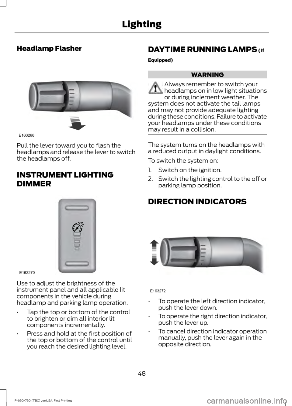
Headlamp Flasher
Pull the lever toward you to flash the
headlamps and release the lever to switch
the headlamps off.
INSTRUMENT LIGHTING
DIMMER
Use to adjust the brightness of the
instrument panel and all applicable lit
components in the vehicle during
headlamp and parking lamp operation.
•
Tap the top or bottom of the control
to brighten or dim all interior lit
components incrementally.
• Press and hold at the first position of
the top or bottom of the control until
you reach the desired lighting level. DAYTIME RUNNING LAMPS (If
Equipped) WARNING
Always remember to switch your
headlamps on in low light situations
or during inclement weather. The
system does not activate the tail lamps
and may not provide adequate lighting
during these conditions. Failure to activate
your headlamps under these conditions
may result in a collision. The system turns on the headlamps with
a reduced output in daylight conditions.
To switch the system on:
1. Switch on the ignition.
2.
Switch the lighting control to the off or
parking lamp position.
DIRECTION INDICATORS •
To operate the left direction indicator,
push the lever down.
• To operate the right direction indicator,
push the lever up.
• To cancel direction indicator operation
manually, push the lever again in the
opposite direction.
48
F-650/750 (TBC) , enUSA, First Printing LightingE163268 E163270 E163272
Page 52 of 382
If your vehicle is a tractor, the direction
indicators may not shut off when you
complete a turn. This is normal. Contact
an authorized dealer if there are any
questions about your vehicle
’s options.
INTERIOR LAMPS
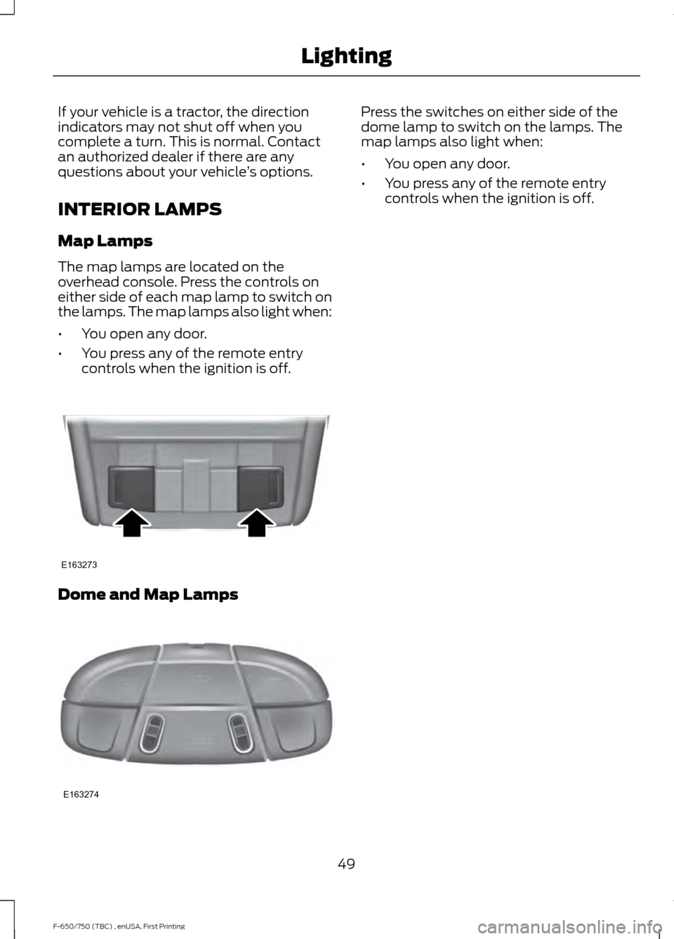
Map Lamps
The map lamps are located on the
overhead console. Press the controls on
either side of each map lamp to switch on
the lamps. The map lamps also light when:
• You open any door.
• You press any of the remote entry
controls when the ignition is off. Dome and Map Lamps Press the switches on either side of the
dome lamp to switch on the lamps. The
map lamps also light when:
•
You open any door.
• You press any of the remote entry
controls when the ignition is off.
49
F-650/750 (TBC) , enUSA, First Printing LightingE163273 E163274
Page 53 of 382
POWER WINDOWS (If Equipped)
WARNINGS
Do not leave children unattended in
your vehicle and do not let them play
with the power windows. They may
seriously injure themselves. When closing the power windows,
you should verify they are free of
obstructions and make sure that
children and pets are not in the proximity
of the window openings. Note:
You may hear a pulsing noise when
just one of the windows is open. Lower the
opposite window slightly to reduce this
noise.
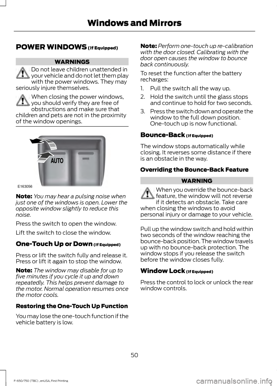
Press the switch to open the window.
Lift the switch to close the window.
One-Touch Up or Down
(If Equipped)
Press or lift the switch fully and release it.
Press or lift it again to stop the window.
Note: The window may disable for up to
five minutes if you cycle it up and down
repeatedly. This helps prevent damage to
the motor. Normal operation resumes once
the motor cools.
Restoring the One-Touch Up Function
You may lose the one-touch function if the
vehicle battery is low. Note:
Perform one-touch up re-calibration
with the door closed. Calibrating with the
door open causes the window to bounce
back continuously.
To reset the function after the battery
recharges:
1. Pull the switch all the way up.
2. Hold the switch until the glass stops and continue to hold for two seconds.
3. Press the switch down and operate the
window to the full down position.
One-touch up is now functional.
Bounce-Back
(If Equipped)
The window stops automatically while
closing. It reverses some distance if there
is an obstacle in the way.
Overriding the Bounce-Back Feature WARNING
When you override the bounce-back
feature, the window will not reverse
if it detects an obstacle. Take care
when closing the windows to avoid
personal injury or damage to your vehicle. Pull up the window switch and hold within
two seconds of the window reaching the
bounce-back position. The window travels
up with no bounce-back protection. The
window stops if you release the switch
before the window closes fully.
Window Lock
(If Equipped)
Press the control to lock or unlock the rear
window controls.
50
F-650/750 (TBC) , enUSA, First Printing Windows and MirrorsE163056
Page 54 of 382
EXTERIOR MIRRORS
Auxiliary Convex Mirrors
Convex mirrors are a ball-stud design for
precise adjustment to maximize viewing
area.
Power Exterior Mirrors (If Equipped)
WARNING
Do not adjust the mirrors when your
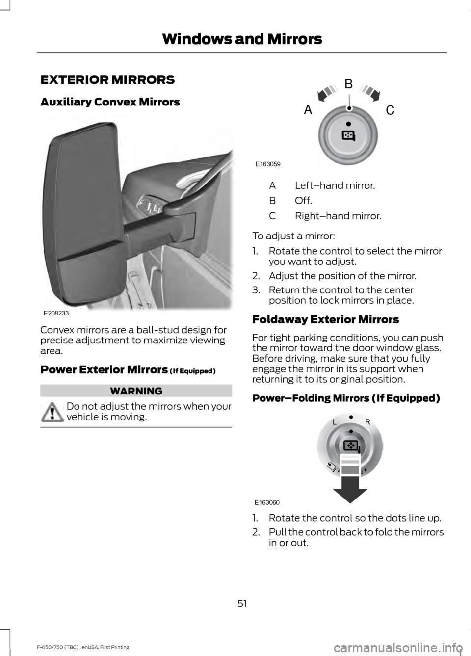
vehicle is moving. Left
–hand mirror.
A
Off.B
Right–hand mirror.
C
To adjust a mirror:
1. Rotate the control to select the mirror you want to adjust.
2. Adjust the position of the mirror.
3. Return the control to the center position to lock mirrors in place.
Foldaway Exterior Mirrors
For tight parking conditions, you can push
the mirror toward the door window glass.
Before driving, make sure that you fully
engage the mirror in its support when
returning it to its original position.
Power–Folding Mirrors (If Equipped) 1. Rotate the control so the dots line up.
2.
Pull the control back to fold the mirrors
in or out.
51
F-650/750 (TBC) , enUSA, First Printing Windows and MirrorsE208233 E163059
B
AC E163060
Page 55 of 382
Note:
If you repeatedly fold and unfold the
mirrors several times within one minute, the
system may disable to protect the motors
from overheating. It resets to normal
function automatically within three to five
minutes.
You can also fold a mirror manually by
pushing it toward the door window glass.
After you manually adjust the mirror, you
need to reset it.
To reset the power –folding mirror system
and return it to its normal function:
• Fold the mirror manually by pushing it
toward the door window glass.
• Use the power –fold control to fold and
unfold the mirror two or three times.
The mirror makes a sound as it resets.
Heated Exterior Mirrors (If Equipped)
See
Heated Exterior Mirrors (page 72).
Signal Indicator Mirrors
(If Equipped)
The outer portion of the appropriate mirror
housing blinks when you use the direction
indicator.
Clearance Lamps
(If Equipped)
The lower, outer part of the mirror housings
light when you switch on the headlamps
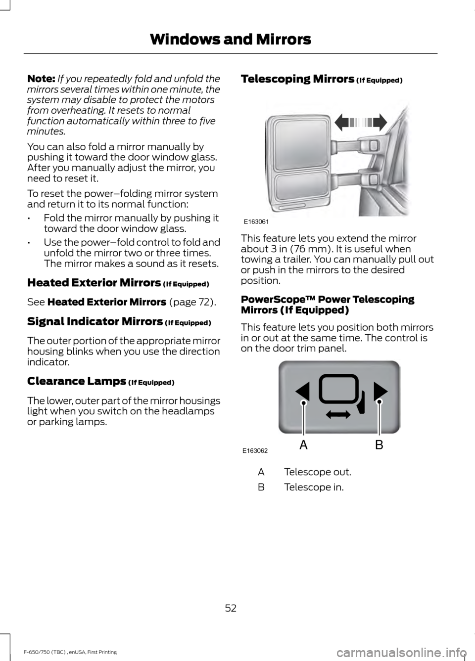
or parking lamps. Telescoping Mirrors
(If Equipped) This feature lets you extend the mirror
about
3 in (76 mm). It is useful when
towing a trailer. You can manually pull out
or push in the mirrors to the desired
position.
PowerScope ™ Power Telescoping
Mirrors (If Equipped)
This feature lets you position both mirrors
in or out at the same time. The control is
on the door trim panel. Telescope out.
A
Telescope in.
B
52
F-650/750 (TBC) , enUSA, First Printing Windows and MirrorsE163061 E163062BA
Page 56 of 382
To adjust the mirrors:
•
Press and hold the control.
• When you position the mirrors in or out,
the motors run as long as you hold the
control. The running motors allow you
to make adjustments as needed.
• After positioning the mirrors, return the
control to the center position to help
protect the motors from overheating.
INTERIOR MIRROR (If Equipped) WARNING
Do not adjust the mirror when your
vehicle is moving.
Note:
Do not clean the housing or glass of
any mirror with harsh abrasives, fuel or other
petroleum or ammonia-based cleaning
products
You can adjust the interior mirror to your
preference. Some mirrors also have a
second pivot point. This lets you move the
mirror head up or down and from side to
side.
Pull the tab below the mirror toward you
to reduce glare at night. SUN VISORS
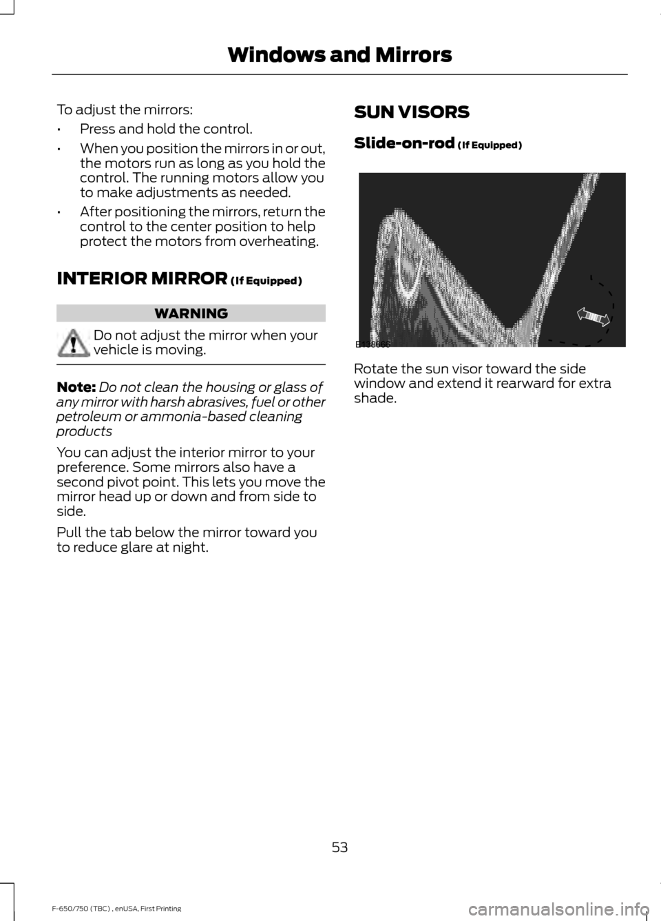
Slide-on-rod
(If Equipped) Rotate the sun visor toward the side
window and extend it rearward for extra
shade.
53
F-650/750 (TBC) , enUSA, First Printing Windows and MirrorsE138666
Page 57 of 382
GAUGES
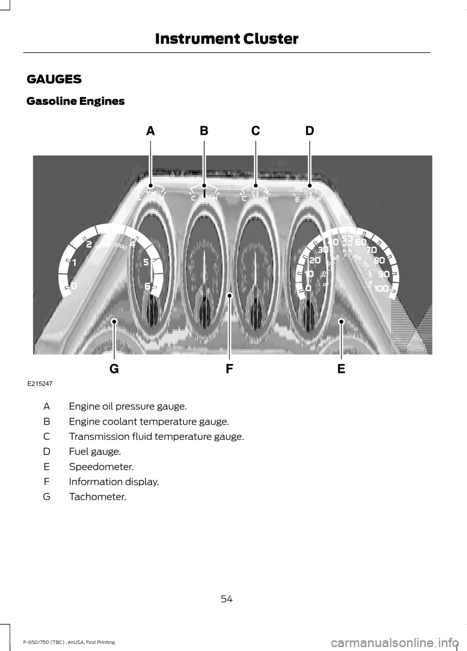
Gasoline Engines
Engine oil pressure gauge.
A
Engine coolant temperature gauge.
B
Transmission fluid temperature gauge.
C
Fuel gauge.
D
Speedometer.
E
Information display.
F
Tachometer.
G
54
F-650/750 (TBC) , enUSA, First Printing Instrument ClusterE215247
Page 58 of 382
Engine Oil Pressure Gauge
Indicates engine oil pressure. The needle
should stay in the normal operating range
(between L and H). If the needle falls
below the normal range, stop the vehicle,
switch off the engine and check the engine
oil level. Add oil if needed. If the oil level is
correct, have your vehicle checked by an
authorized dealer.
Engine Coolant Temperature
Gauge
WARNING
Never remove the coolant reservoir
cap while the engine is running or hot.
Indicates engine coolant temperature. At
normal operating temperature, the level
indicator is in the normal range. If the
engine coolant temperature exceeds the
normal range, stop the vehicle as soon as
safely possible, switch off the engine and
let the engine cool.
Transmission Fluid Temperature
Gauge
Indicates transmission fluid temperature.
At normal operating temperature, the level
indicator is in the normal range. If the
transmission fluid temperature exceeds
the normal range, stop the vehicle as soon
as safely possible and verify the airflow is
not restricted such as snow or debris
blocking airflow through the grille.
Special operating conditions, such as
snowplowing, towing or off-road use, can
cause higher than normal operating
temperatures. See Special Operating
Conditions Scheduled Maintenance
(page
328). Operating the transmission for extended
periods with the gauge in the higher than
normal area may cause internal
transmission damage. We recommend
altering the severity of the driving
conditions to lower the transmission
temperature into the normal range. If the
gauge continues to show high
temperatures, contact an authorized
dealer.
Fuel Gauge
Note:
The fuel gauge may vary slightly
when your vehicle is moving or on a gradient.
Switch the ignition on. The fuel gauge
indicates approximately how much fuel is
in the fuel tank. The arrow adjacent to the
fuel pump symbol indicates on which side
of your vehicle the fuel filler door is located.
The needle should move toward F when
you refuel your vehicle. If the needle points
to E after adding fuel, this indicates your
vehicle needs service soon.
After refueling, some variability in needle
position is normal:
• It may take a short time for the needle
to reach F after leaving the gas station.
This is normal and depends upon the
slope of pavement at the gas station.
• The fuel amount dispensed into the
tank is a little less or more than the
gauge indicated. This is normal and
depends upon the slope of pavement
at the gas station.
• If the gas station nozzle shuts off
before the tank is full, try a different
gas pump nozzle.
Gauge Package
(If Equipped)
If your vehicle is equipped with the optional
gauge package, it has some or all of the
following gauges:
55
F-650/750 (TBC) , enUSA, First Printing Instrument Cluster
Page 59 of 382
•
Transmission temperature gauge:
Displays the transmission fluid
temperature at the transmission sump.
• Hourmeter: Displays the hours of
engine run time.
• Voltmeter:
Displays electrical system
voltage. Information Display
Odometer
Located in the bottom of the information
display. Registers the accumulated
distance your vehicle has traveled.
Trip Computer
See
General Information (page 62).
Vehicle Settings and Personalization
See
General Information (page 62).
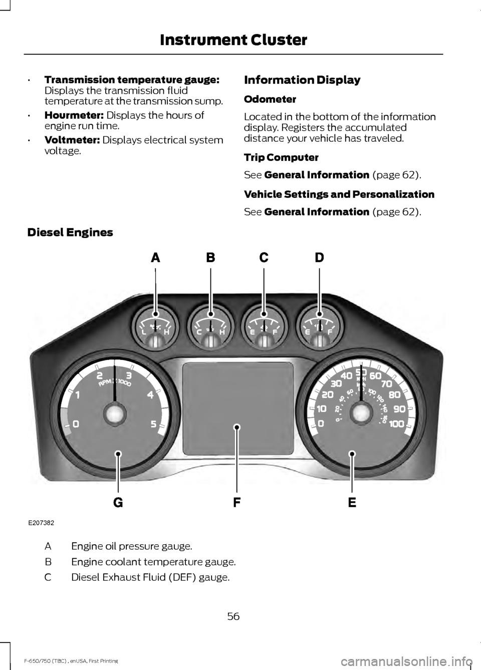
Diesel Engines Engine oil pressure gauge.
A
Engine coolant temperature gauge.
B
Diesel Exhaust Fluid (DEF) gauge.
C
56
F-650/750 (TBC) , enUSA, First Printing Instrument ClusterE207382
Page 60 of 382
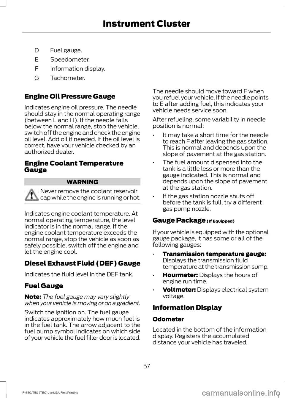
Fuel gauge.
D
Speedometer.
E
Information display.
F
Tachometer.
G
Engine Oil Pressure Gauge
Indicates engine oil pressure. The needle
should stay in the normal operating range
(between L and H). If the needle falls
below the normal range, stop the vehicle,
switch off the engine and check the engine
oil level. Add oil if needed. If the oil level is
correct, have your vehicle checked by an
authorized dealer.
Engine Coolant Temperature
Gauge WARNING
Never remove the coolant reservoir
cap while the engine is running or hot.
Indicates engine coolant temperature. At
normal operating temperature, the level
indicator is in the normal range. If the
engine coolant temperature exceeds the
normal range, stop the vehicle as soon as
safely possible, switch off the engine and
let the engine cool.
Diesel Exhaust Fluid (DEF) Gauge
Indicates the fluid level in the DEF tank.
Fuel Gauge
Note:
The fuel gauge may vary slightly
when your vehicle is moving or on a gradient.
Switch the ignition on. The fuel gauge
indicates approximately how much fuel is
in the fuel tank. The arrow adjacent to the
fuel pump symbol indicates on which side
of your vehicle the fuel filler door is located. The needle should move toward F when
you refuel your vehicle. If the needle points
to E after adding fuel, this indicates your
vehicle needs service soon.
After refueling, some variability in needle
position is normal:
•
It may take a short time for the needle
to reach F after leaving the gas station.
This is normal and depends upon the
slope of pavement at the gas station.
• The fuel amount dispensed into the
tank is a little less or more than the
gauge indicated. This is normal and
depends upon the slope of pavement
at the gas station.
• If the gas station nozzle shuts off
before the tank is full, try a different
gas pump nozzle.
Gauge Package (If Equipped)
If your vehicle is equipped with the optional
gauge package, it has some or all of the
following gauges:
• Transmission temperature gauge:
Displays the transmission fluid
temperature at the transmission sump.
• Hourmeter:
Displays the hours of
engine run time.
• Voltmeter:
Displays electrical system
voltage.
Information Display
Odometer
Located in the bottom of the information
display. Registers the accumulated
distance your vehicle has traveled.
57
F-650/750 (TBC) , enUSA, First Printing Instrument Cluster