sensor FORD FESTIVA 1991 Repair Manual
[x] Cancel search | Manufacturer: FORD, Model Year: 1991, Model line: FESTIVA, Model: FORD FESTIVA 1991Pages: 454, PDF Size: 9.53 MB
Page 211 of 454
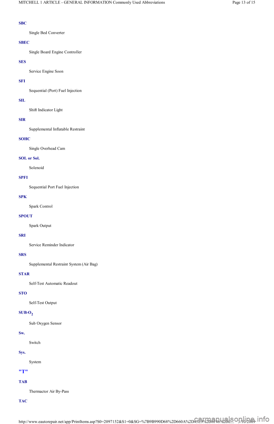
SBC
Single Bed Converter
SBEC
Single Board Engine Controller
SES
Service Engine Soon
SFI
Sequential (Port) Fuel Injection
SIL
Shift Indicator Light
SIR
Supplemental Inflatable Restraint
SOHC
Single Overhead Cam
SOL or Sol.
Solenoid
SPFI
Sequential Port Fuel Injection
SPK
Spark Control
SPOUT
Spark Output
SRI
Service Reminder Indicator
SRS
Supplemental Restraint System (Air Bag)
STAR
Self-Test Automatic Readout
STO
Self-Test Output
SUB-O
2
Sub Oxygen Sensor
Sw.
Switch
Sys.
System
"T"
TAB
Thermactor Air By-Pass
TAC
Page 13 of 15 MITCHELL 1 ARTICLE - GENERAL INFORMATION Commonly Used Abbreviations
3/10/2009 http://www.eautorepair.net/app/PrintItems.asp?S0=2097152&S1=0&SG=%7B9B990D68%2D660A%2D45E9%2D8F46%2DE
...
Page 212 of 454
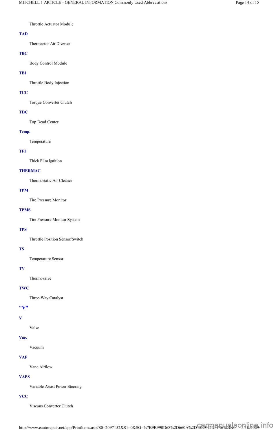
Throttle Actuator Module
TAD
Thermactor Air Diverter
TBC
Body Control Module
TBI
Throttle Body Injection
TCC
Torque Converter Clutch
TDC
Top Dead Center
Temp.
Temperature
TFI
Thick Film Ignition
THERMAC
Thermostatic Air Cleaner
TPM
Tire Pressure Monitor
TPMS
Tire Pressure Monitor System
TPS
Throttle Position Sensor/Switch
TS
Temperature Sensor
TV
Thermovalve
TWC
Three-Way Catalyst
"V"
V
Valve
Vac.
Vacuum
VAF
Vane Airflow
VAPS
Variable Assist Power Steering
VCC
Viscous Converter Clutch
Page 14 of 15 MITCHELL 1 ARTICLE - GENERAL INFORMATION Commonly Used Abbreviations
3/10/2009 http://www.eautorepair.net/app/PrintItems.asp?S0=2097152&S1=0&SG=%7B9B990D68%2D660A%2D45E9%2D8F46%2DE
...
Page 213 of 454
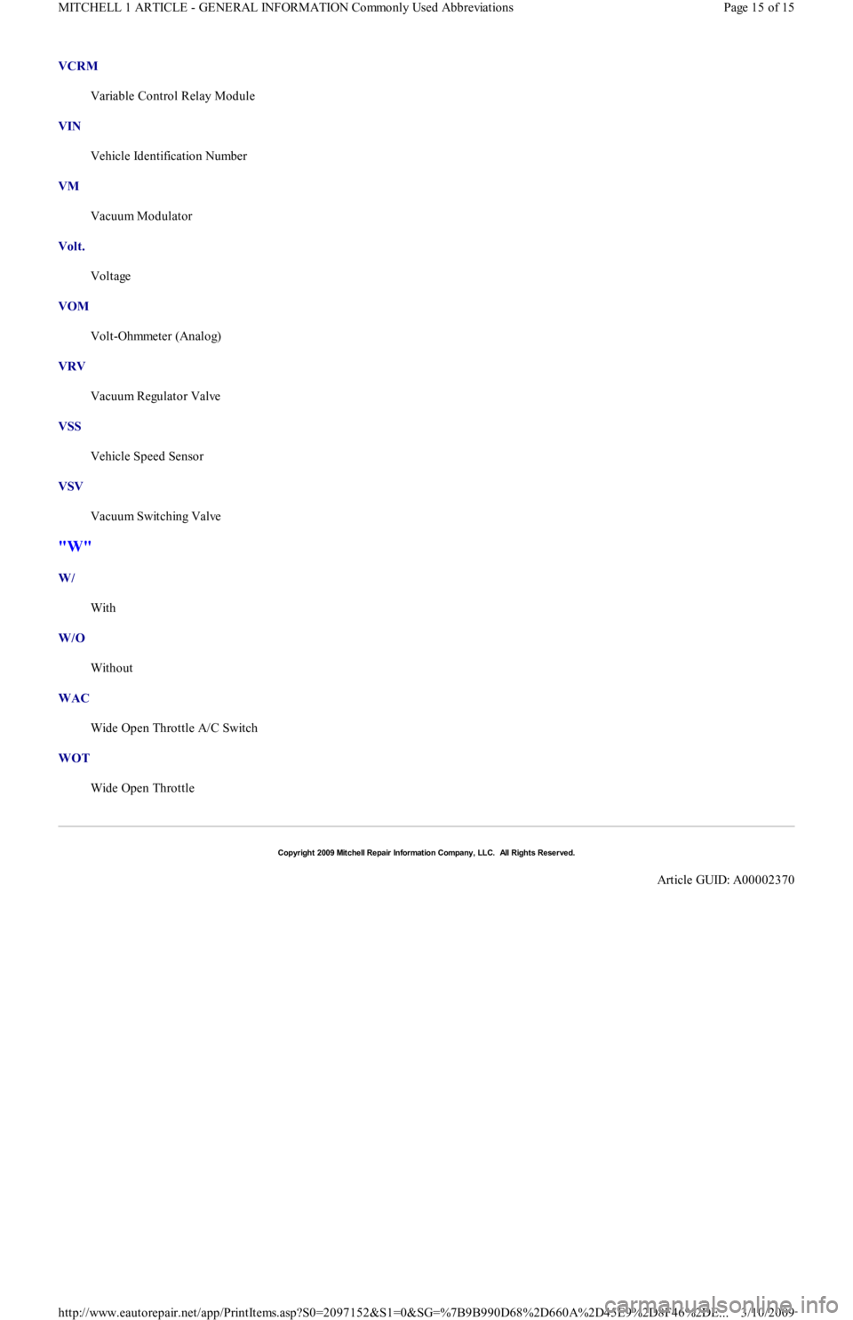
VCRM
Variable Control Relay Module
VIN
Vehicle Identification Number
VM
Vacuum Modulator
Volt.
Voltage
VOM
Volt-Ohmmeter (Analog)
VRV
Vacuum Regulator Valve
VSS
Vehicle Speed Sensor
VSV
Vacuum Switching Valve
"W"
W/
With
W/O
Without
WAC
Wide Open Throttle A/C Switch
WOT
Wide Open Throttle
Copyr ight 2009 Mitchell Repair Information Company, LLC. All Rights Reserved.
Article GUID: A00002370
Page 15 of 15 MITCHELL 1 ARTICLE - GENERAL INFORMATION Commonly Used Abbreviations
3/10/2009 http://www.eautorepair.net/app/PrintItems.asp?S0=2097152&S1=0&SG=%7B9B990D68%2D660A%2D45E9%2D8F46%2DE
...
Page 230 of 454
IGNITION SYSTEM TROUBLE SHOOTING
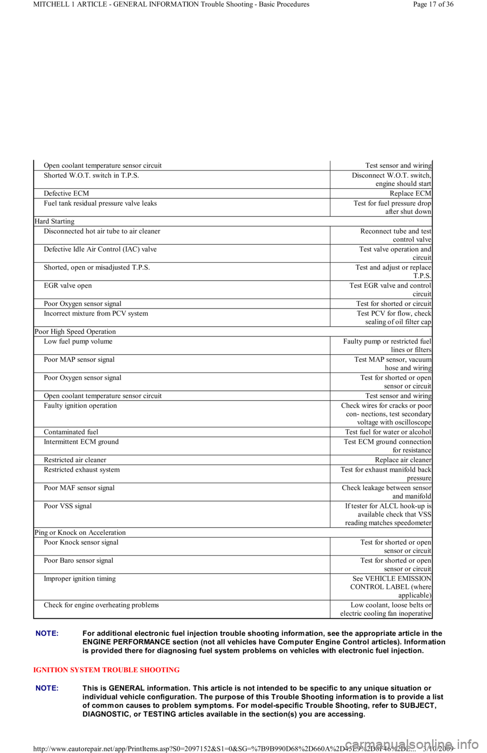
Open coolant temperature sensor circuitTest sensor and wiring
Shorted W.O.T. switch in T.P.S.Disconnect W.O.T. switch,
engine should start
Defective ECMReplace ECM
Fuel tank residual pressure valve leaksTest for fuel pressure drop
after shut down
Hard Starting
Disconnected hot air tube to air cleanerReconnect tube and test
control valve
Defective Idle Air Control (IAC) valveTest valve operation and
circuit
Shorted, open or misadjusted T.P.S.Test and adjust or replace
T.P.S.
EGR valve openTest EGR valve and control
circuit
Poor Oxygen sensor signalTest for shorted or circuit
Incorrect mixture from PCV systemTest PCV for flow, check
sealing of oil filter cap
Poor High Speed Operation
Low fuel pump volumeFaulty pump or restricted fuel
lines or filters
Poor MAP sensor signalTest MAP sensor, vacuum
hose and wiring
Poor Oxygen sensor signalTest for shorted or open
sensor or circuit
Open coolant temperature sensor circuitTest sensor and wiring
Faulty ignition operationCheck wires for cracks or poor
con- nections, test secondary
voltage with oscilloscope
Contaminated fuelTest fuel for water or alcohol
Intermittent ECM groundTest ECM ground connection
for resistance
Restricted air cleanerReplace air cleaner
Restricted exhaust systemTest for exhaust manifold back
pressure
Poor MAF sensor signalCheck leakage between sensor
and manifold
Poor VSS signalIf tester for ALCL hook-up is
available check that VSS
reading matches speedometer
Ping or Knock on Acceleration
Poor Knock sensor signalTest for shorted or open
sensor or circuit
Poor Baro sensor signalTest for shorted or open
sensor or circuit
Improper ignition timingSee VEHICLE EMISSION
CONTROL LABEL (where
applicable)
Check for engine overheating problemsLow coolant, loose belts or
electric cooling fan inoperative
NOTE:For additional electronic fuel injection trouble shooting inform ation, see the appropriate article in the
ENGINE PERFORMANCE section (not all vehicles have Com puter Engine Control articles). Inform ation
is provided there for diagnosing fuel system problem s on vehicles with electronic fuel injection.
NOTE:This is GENERAL inform ation. This article is not intended to be specific to any unique situation or
individual vehicle configuration. T he purpose of this T rouble Shooting inform ation is to provide a list
of com m on causes to problem sym ptom s. For m odel-specific T rouble Shooting, refer to SUBJECT ,
DIAGNOST IC, or T EST ING articles available in the section(s) you are accessing.
Page 17 of 36 MITCHELL 1 ARTICLE - GENERAL INFORMATION Trouble Shooting - Basic Procedures
3/10/2009 http://www.eautorepair.net/app/PrintItems.asp?S0=2097152&S1=0&SG=%7B9B990D68%2D660A%2D45E9%2D8F46%2DE
...
Page 251 of 454
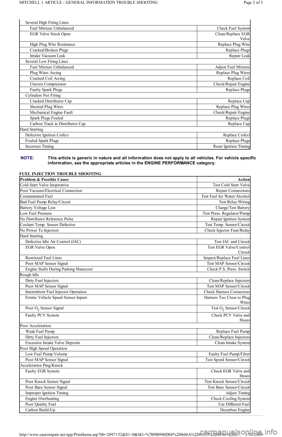
FUEL INJECTION TROUBLE SHOOTING
Se ve r a l High F ir in g Lin e s
Fuel Mixture UnbalancedCheck Fuel System
EGR Valve Stuck OpenClean/Replace EGR
Valve
High Plug Wire ResistanceReplace Plug Wire
Cracked/Broken PlugsReplace Plugs
Intake Vacuum LeakRepair Leak
Several Low Firing Lines
Fuel Mixture UnbalancedAdjust Fuel Mixture
Plug Wires ArcingReplace Plug Wires
Cracked Coil ArcingReplace Coil
Uneven CompressionCheck/Repair Engine
Faulty Spark PlugsReplace Plugs
Cylinders Not Firing
Cracked Distributor CapReplace Cap
Shorted Plug WiresReplace Plug Wires
Mechanical Engine FaultCheck/Repair Engine
Spark Plugs FouledReplace Plugs
Carbon Track in Distributor CapReplace Cap
Hard Starting
Defective Ignition Coil(s)Replace Coil(s)
Fouled Spark PlugsReplace Plugs
Incorrect TimingReset Ignition Timing
NOTE:T his article is generic in nature and all inform ation does not apply to all vehicles. For vehicle specific
inform ation, see the appropriate articles in the ENGINE PERFORMANCE category.
Problem & Possible CauseAction
Cold Start Valve InoperativeTest Cold Start Valve
Poor Vacuum/Electrical ConnectionRepair Connections
Contaminated FuelTest Fuel for Water/Alcohol
Bad Fuel Pump Relay/CircuitTest Relay/Wiring
Battery Voltage LowCharge/Test Battery
Low Fuel PressureTest Press. Regulator/Pump
No Distributor Reference PulseRepair Ignition System
Coolant Temp. Sensor DefectiveTest Temp. Sensor/Circuit
No Power To InjectorsCheck Injector Fuse/Relay
Hard Starting
Defective Idle Air Control (IAC)Test IAC and Circuit
EGR Valve OpenTest EGR Valve/Control
Circuit
Restricted Fuel LinesInspect/Replace Fuel Lines
Poor MAP Sensor SignalTest MAP Sensor/Circuit
Engine Stalls During Parking ManeuverCheck P.S. Press. Switch
Rough Idle
Dirty Fuel InjectorsClean/Replace Injectors
Poor MAP Sensor SignalTest MAP Sensor/Circuit
Intermittent Fuel Injector OperationCheck Harness Connectors
Erratic Vehicle Speed Sensor InputsHarness Too Close to Plug
Wires
Poor O2 Sensor SignalTest O2 Sensor/Circuit
Faulty PCV SystemCheck PCV Valve and
Hoses
Poor Acceleration
Weak Fuel PumpReplace Fuel Pump
Dirty Fuel InjectorsClean/Replace Injectors
Excessive Intake Valve DepositsClean Intake System
Poor High Speed Operation
Low Fuel Pump VolumeFaulty Fuel Pump/Filter
Poor MAP Sensor SignalTest Speed Sensor/Circuit
Acceleration Ping/Knock
Faulty EGR SystemCheck EGR Valve and
Hoses
Poor Knock Sensor SignalTest Knock Sensor/Circuit
Poor Baro Sensor SignalTest Baro Sensor/Circuit
Improper Ignition TimingAdjust Timing
Engine OverheatingCheck Cooling System
Poor Quality FuelUse Different Fuel
Carbon Build-UpDecarbon Engine
Page 2 of 3 MITCHELL 1 ARTICLE - GENERAL INFORMATION TROUBLE SHOOTING
3/10/2009 http://www.eautorepair.net/app/PrintItems.asp?S0=2097152&S1=0&SG=%7B9B990D68%2D660A%2D45E9%2D8F46%2DE
...
Page 268 of 454

Fig. 14: Typical Negative Backpressure EGR Valve
Courtesy of GENERAL MOTORS CORP.
Digital EGR Valve
The digital EGR valve operates independently of engine manifold vacuum. This valve controls EGR flow through 3 orifices. These 3 orifices
are opened and closed by electric solenoids. The solenoids are, in turn, controlled by the Electronic Control Module (ECM). When a
solenoid is energized, the armature with attached shaft and swivel pintle is lifted, opening the orifice. See Fig. 15
.
The ECM uses inputs from the Coolant Temperature Sensor (CTS), Throttle Position Sensor (TPS) and Mass Airflow (MAF) sensors to
control the EGR orifices to make 7 different combinations for precise EGR flow control. At idle, the EGR valve allows a very small amount of
exhaust gas to enter the intake manifold. This EGR valve normally operates above idle speed during warm engine operation.
Verify EGR valve is present and not modified or purposely damaged. Ensure thermal vacuum switches, pressure transducers, speed switches,
etc., (if applicable) are not by-passed or modified. Ensure vacuum hose(s) to EGR valve is not plugged. Ensure electrical connector to EGR
valve is not disconnected.
Page 8 of 12 MITCHELL 1 ARTICLE - EMISSION CONTROL VISUAL INSPECTION PROCEDURES 1983-93 GENERAL INFORMATI
...
3/10/2009 http://www.eautorepair.net/app/PrintItems.asp?S0=2097152&S1=0&SG=%7B9B990D68%2D660A%2D45E9%2D8F46%2DE
...
Page 269 of 454
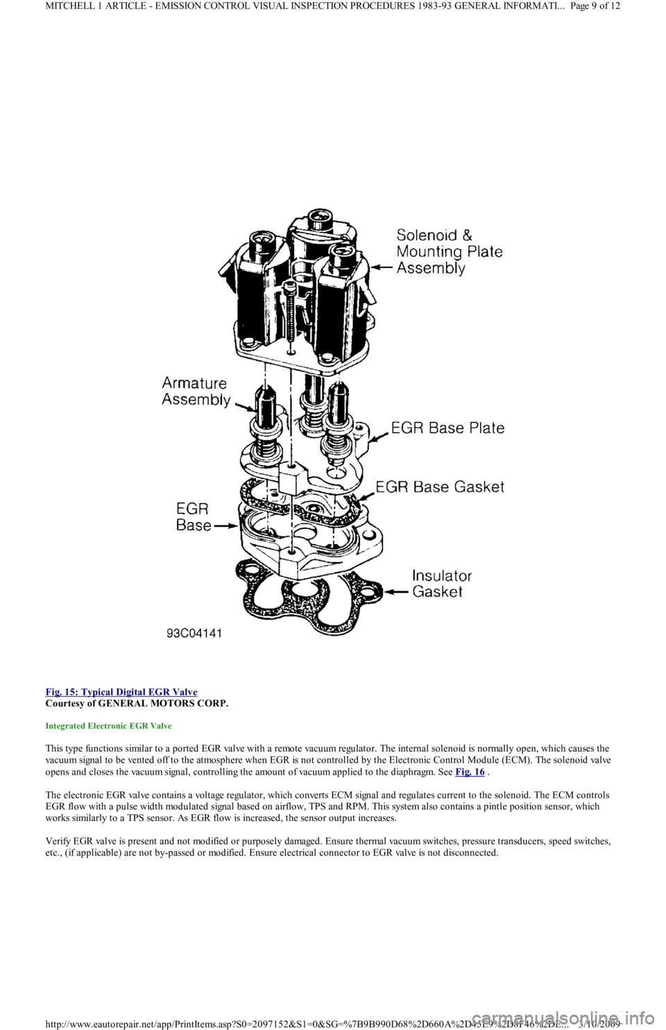
Fig. 15: Typical Digital EGR Valve
Courtesy of GENERAL MOTORS CORP.
Integrated Electronic EGR Valve
This type functions similar to a ported EGR valve with a remote vacuum regulator. The internal solenoid is normally open, which causes the
vacuum signal to be vented off to the atmosphere when EGR is not controlled by the Electronic Control Module (ECM). The solenoid valve
opens and closes the vacuum signal, controlling the amount of vacuum applied to the diaphragm. See Fig. 16
.
The electronic EGR valve contains a voltage regulator, which converts ECM signal and regulates current to the solenoid. The ECM controls
EGR flow with a pulse width modulated signal based on airflow, TPS and RPM. This system also contains a pintle position sensor, which
works similarly to a TPS sensor. As EGR flow is increased, the sensor output increases.
Verify EGR valve is present and not modified or purposely damaged. Ensure thermal vacuum switches, pressure transducers, speed switches,
etc., (if applicable) are not by-passed or modified. Ensure electrical connector to EGR valve is not disconnected.
Page 9 of 12 MITCHELL 1 ARTICLE - EMISSION CONTROL VISUAL INSPECTION PROCEDURES 1983-93 GENERAL INFORMATI
...
3/10/2009 http://www.eautorepair.net/app/PrintItems.asp?S0=2097152&S1=0&SG=%7B9B990D68%2D660A%2D45E9%2D8F46%2DE
...
Page 270 of 454
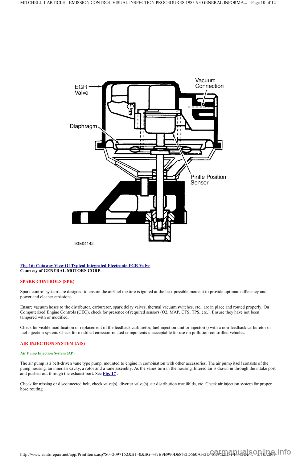
Fig. 16: Cutaway View Of Typical Integrated Electronic EGR Valve
Courtesy of GENERAL MOTORS CORP.
SPARK CONTROLS (SPK)
Spark control systems are designed to ensure the air/fuel mixture is ignited at the best possible moment to provide optimum efficiency and
power and cleaner emissions.
Ensure vacuum hoses to the distributor, carburetor, spark delay valves, thermal vacuum switches, etc., are in place and routed properly. On
Computerized Engine Controls (CEC), check for presence of required sensors (O2, MAP, CTS, TPS, etc.). Ensure they have not been
tampered with or modified.
Check for visible modification or replacement of the feedback carburetor, fuel injection unit or injector(s) with a non-feedback carburetor or
fuel injection system. Check for modified emission-related components unacceptable for use on pollution-controlled vehicles.
AIR INJECTION SYSTEM (AIS)
Air Pump Injection System (AP)
The air pump is a belt-driven vane type pump, mounted to engine in combination with other accessories. The air pump itself consists of the
pump housing, an inner air cavity, a rotor and a vane assembly. As the vanes turn in the housing, filtered air is drawn in through the intake port
and pushed out through the exhaust port. See Fig. 17
.
Check for missing or disconnected belt, check valve(s), diverter valve(s), air distribution manifolds, etc. Check air injection system for proper
hose routing.
Page 10 of 12 MITCHELL 1 ARTICLE - EMISSION CONTROL VISUAL INSPECTION PROCEDURES 1983-93 GENERAL INFORMA...
3/10/2009 http://www.eautorepair.net/app/PrintItems.asp?S0=2097152&S1=0&SG=%7B9B990D68%2D660A%2D45E9%2D8F46%2DE
...
Page 271 of 454
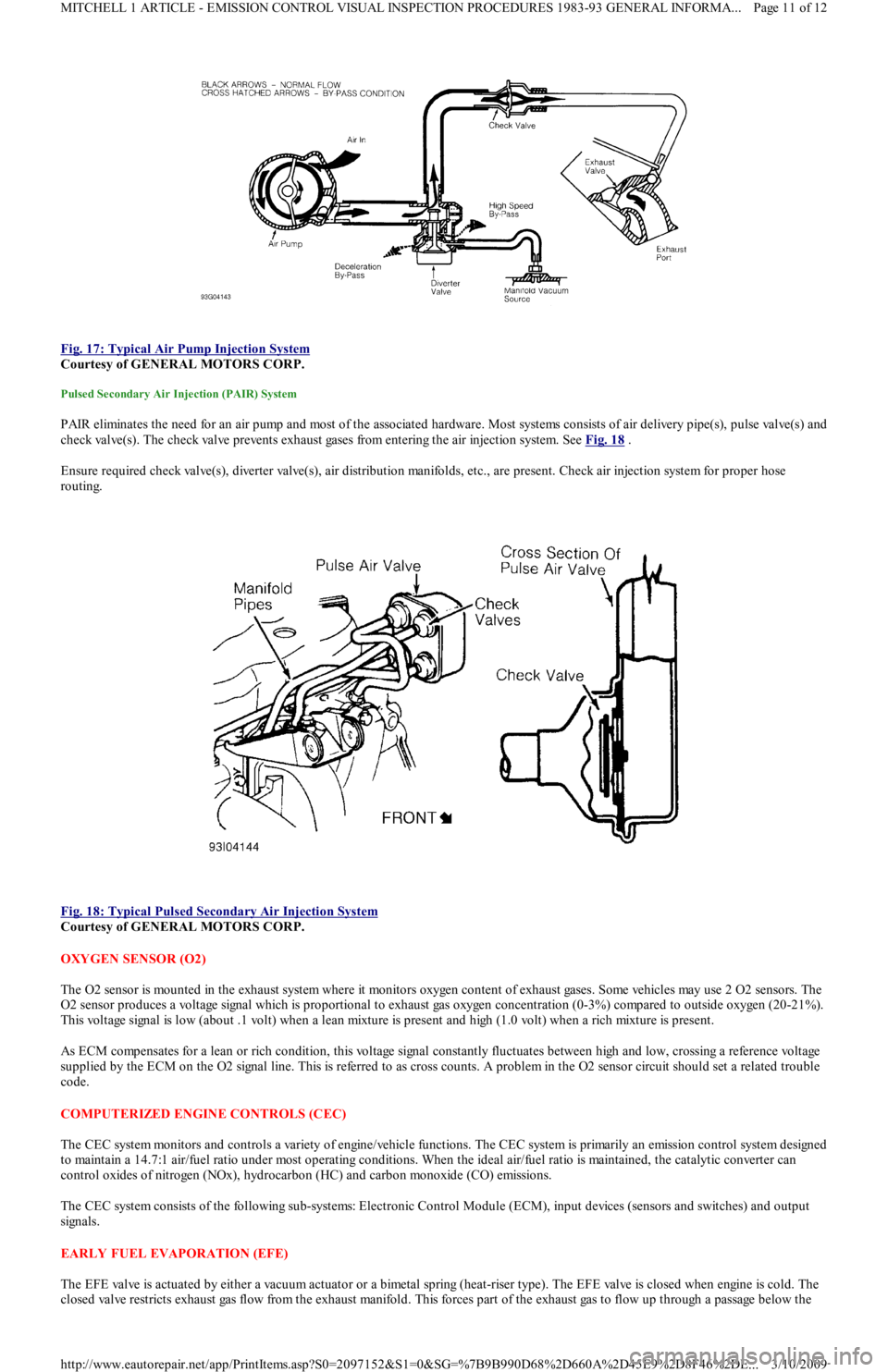
Fig. 17: Typical Air Pump Injection System
Courtesy of GENERAL MOTORS CORP.
Pulsed Secondary Air Injection (PAIR) System
PAIR eliminates the need for an air pump and most of the associated hardware. Most systems consists of air delivery pipe(s), pulse valve(s) and
check valve(s). The check valve prevents exhaust gases from entering the air injection system. See Fig. 18
.
Ensure required check valve(s), diverter valve(s), air distribution manifolds, etc., are present. Check air injection system for proper hose
routing.
Fig. 18: Typical Pulsed Secondary Air Injection System
Courtesy of GENERAL MOTORS CORP.
OXYGEN SENSOR (O2)
The O2 sensor is mounted in the exhaust system where it monitors oxygen content of exhaust gases. Some vehicles may use 2 O2 sensors. The
O2 sensor produces a voltage signal which is proportional to exhaust gas oxygen concentration (0-3%) compared to outside oxygen (20-21%).
This voltage signal is low (about .1 volt) when a lean mixture is present and high (1.0 volt) when a rich mixture is present.
As ECM compensates for a lean or rich condition, this voltage signal constantly fluctuates between high and low, crossing a reference voltage
supplied by the ECM on the O2 signal line. This is referred to as cross counts. A problem in the O2 sensor circuit should set a related trouble
code.
COMPUTERIZED ENGINE CONTROLS (CEC)
The CEC system monitors and controls a variety of engine/vehicle functions. The CEC system is primarily an emission control system designed
to maintain a 14.7:1 air/fuel ratio under most operating conditions. When the ideal air/fuel ratio is maintained, the catalytic converter can
control oxides of nitrogen (NOx), hydrocarbon (HC) and carbon monoxide (CO) emissions.
The CEC system consists of the following sub-systems: Electronic Control Module (ECM), input devices (sensors and switches) and output
signals.
EARLY FUEL EVAPORATION (EFE)
The EFE valve is actuated by either a vacuum actuator or a bimetal spring (heat-riser type). The EFE valve is closed when engine is cold. The
closed valve restricts exhaust gas flow from the exhaust manifold. This forces part of the exhaust gas to flow up through a passage below the
Page 11 of 12 MITCHELL 1 ARTICLE - EMISSION CONTROL VISUAL INSPECTION PROCEDURES 1983-93 GENERAL INFORMA...
3/10/2009 http://www.eautorepair.net/app/PrintItems.asp?S0=2097152&S1=0&SG=%7B9B990D68%2D660A%2D45E9%2D8F46%2DE
...
Page 275 of 454
Back To Article
GENERAL INFORMATION
How To Use The Engine Perform ance Section - 1989 & Newer Models
* PLEASE READ THIS FIRST *
HOW TO USE THE ENGINE PERFORMANCE SECTION
Congratulations, you have purchased the most advanced automotive repair and service information available. This information can help you, as
a professional automotive technician, to maintain top vehicle performance, and correct driveability problems on today's high-tech vehicles.
For your convenience and ease in use, all of our engine performance service and repair information is consistently organized by manufacturer,
using a progressive diagnostic/workflow approach. Due to the differences in how each manufacturer approaches diagnosis and repair, once
started and inside of an article, that manufacturer may drive the workflow in a direction other than what is outlined here.
The progressive diagnostic/workflow of our data is as follows:
APPLICATION to identify vehicle and system usage.
EMISSION APPLICATION to identify emission system usage.
SPECIFICATIONS to quickly find an engine performance service specification.
ADJUSTMENTS to perform engine performance related routine adjustments.
THEORY & OPERATION to familiarize yourself with new systems and technologies.
BASIC DIAGNOSTIC PROCEDURES located under TESTING & DIAGNOSTICS, also referred to as BASIC TESTING, is used for
performing a basic vehicle inspection and is also the starting point for diagnosis of a "no-start" condition.
SELF-DIAGNOSTICS located under TESTING & DIAGNOSTICS, also referred to as TESTS W/CODES, is where manufacturer
specific procedures for retrieving, identifying and diagnosing DTCs (trouble codes) retained in a control modules memory are located.
TROUBLE SHOOTING - NO CODES located under TESTING & DIAGNOSTICS, also referred to as TESTS W/O CODES, is where
an engine performance problem that does not set a DTC can be potentially isolated through either a SYMPTOM or INTERMITTENTS
duplication procedure.
SYSTEM & COMPONENT TESTING located under TESTING & DIAGNOSTICS, also referred to as SYSTEM/COMPONENT
TESTS, once directed to this article, specific system and component tests can be performed to help isolate faulty component/system
prior to replacement.
PIN VOLTAGE CHARTS provide supplemental information to help determine correct control module input and output signals. Pin
charts may also be referred to as PID charts by some manufacturers.
SENSOR RANGE CHARTS help determine if a sensor is out of calibration. In some cases an out-of-calibration sensor will not set a
DTC (trouble code), resulting in difficult to diagnose driveability symptoms.
VACUUM DIAGRAMS help determine correct routing of vacuum hoses when reinstalling components or performing emission
inspections.
REMOVE, OVERHAUL & INSTALL provides procedures necessary for removing and installing engine performance related
components.
WIRING DIAGRAMS can be used to identify circuits, terminals, wire colors and components referenced in testing procedures. NEW
COLOR WIRING DIAGRAMS (system diagrams) provide an easy method of identifying and tracing circuits.
APPLICATION
INTRODUCTION/ENGINE/VIN ID
Here you will find out how to identify an engine by its Vehicle Identification Number (VIN). The manufacturer's MODEL COVERAGE chart
lists each model and engine option, the fuel system, ignition system and engine code. Engine serial number locations are also shown here, as
well as the VIN code breakdown. Using model lookup in conjunction with VIN and engine ID will identify application information necessary
for servicing vehicle and ordering parts.
EMISSION APPLICATIONS
EMISSION APPLICATION TABLES
Here you will find a chart listing what emission control devices apply to each model. This can be helpful when performing government-
required emissions inspections. For quick reference, major emission systems and devices are listed in bold type in the emission table. Sub
components are listed in light type.
SPECIFICATIONS
NOTE:T his article is generic in nature and all inform ation does not apply to all vehicles. For vehicle specific
inform ation, see the appropriate articles in the ENGINE PERFORMANCE category.
NOTE:T his article is generic in nature and all inform ation does not apply to all vehicles. For vehicle specific
inform ation, see the appropriate articles in the ENGINE PERFORMANCE category.
NOTE:T his article is generic in nature and all inform ation does not apply to all vehicles. For vehicle specific
inform ation, see the appropriate articles in the ENGINE PERFORMANCE category.
NOTE:T his article is generic in nature and all inform ation does not apply to all vehicles. For vehicle specific
inform ation, see the appropriate articles in the ENGINE PERFORMANCE category.
Page 1 of 3 MITCHELL 1 ARTICLE - GENERAL INFORMATION How To Use The Engine Performance Section - 1989 & Newer Models
3/10/2009 http://www.eautorepair.net/app/PrintItems.asp?S0=2097152&S1=0&SG=%7B9B990D68%2D660A%2D45E9%2D8F46%2DE
...