differential FORD FESTIVA 1991 Service Manual
[x] Cancel search | Manufacturer: FORD, Model Year: 1991, Model line: FESTIVA, Model: FORD FESTIVA 1991Pages: 454, PDF Size: 9.53 MB
Page 101 of 454
Back To Article
ENGINE OVERHAUL
1991-92 FORD MOT OR CO. ENGINES 1.3L & 1.6L 4-Cylinder
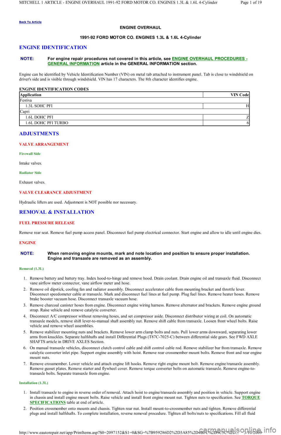
ENGINE IDENTIFICATION
Engine can be identified by Vehicle Identification Number (VIN) on metal tab attached to instrument panel. Tab is close to windshield on
driver's side and is visible through windshield. VIN has 17 characters. The 8th character identifies engine.
ENGINE IDENTIFICATION CODES
ADJUSTMENTS
VALVE ARRANGEMENT
Firewall Side
In t ake val ves.
Radiator Side
Exhaust valves.
VALVE CLEARANCE ADJUSTMENT
Hydraulic lifters are used. Adjustment is NOT possible nor necessary.
REMOVAL & INSTALLATION
FUEL PRESSURE RELEASE
Remove rear seat. Remove fuel pump access panel. Disconnect fuel pump electrical connector. Start engine and allow to idle until engine dies.
ENGINE
Removal (1.3L)
1. Remove battery and battery tray. Index hood-to-hinge and remove hood. Drain coolant. Drain engine oil and transaxle fluid. Disconnect
vane airflow meter connector, vane airflow meter and hose.
2. Remove oil dipstick, cooling fan and radiator assembly. Disconnect accelerator cable from mounting bracket and throttle lever.
Disconnect speedometer cable at transaxle. Mark and disconnect fuel lines at fuel pump. Plug fuel lines. Remove heater hoses. Remove
brake booster vacuum hose. Disconnect transaxle vacuum hose.
3. Remove charcoal canister hoses from engine. Disconnect engine wiring harness. Remove alternator and brackets. Remove engine ground
strap. Raise vehicle and remove catalytic converter.
4. Disconnect A/C compressor without removing hoses, and set compressor aside. Disconnect distributor wiring at coil. On automatic
transaxle models, remove shift lever-to-manual shaft assembly nut. Remove shift cable from transaxle. Loosen front wheel bolts. Raise
vehicle and remove wheel assemblies.
5. Remove stabilizer mounting nuts and brackets. Remove lower arm clamp bolts and nuts. Pull lower arms downward, separating lower
arms from knuckles. Separate halfshafts and install Differential Plugs (T87C-7025-C) between differential side gears. See FWD AXLE
SHAFTS article in DRIVE AXLES Section.
6. On manual transaxle vehicles, disconnect clutch control cable and shift control cable rod. Remove stabilizer bar from transaxle. Remove
catalytic converter inlet pipe. Support engine assembly with hoist. Remove rear crossmember mount bolts. Remove front and rear engine
mount nuts.
7. Remove crossmember. Lower vehicle and attach engine lift hooks. Remove right engine mount bolt. Remove engine/transaxle assembly.
Remove gusset plates. Remove starter and flywheel cover. Remove torque converter bolts on automatic transaxle. Remove engine-to-
transaxle bolts. Separate transaxle from engine.
Installation (1.3L)
1. Install transaxle to engine in reverse order of removal. Attach hoist to engine/transaxle assembly and position in vehicle. Support engine
in chassis and install engine mount bolts. Raise vehicle and install front engine mount nut. Tighten nuts to specification. See TORQUE
SPECIFICATIONS table at end of article.
2. Position crossmember onto mounts and chassis. Tighten rear nut. Install mount-to-crossmember nuts and tighten. Remove differential
plugs and install halfshafts. To complete installation, reverse removal procedure. Tighten all bolts/nuts to specifications. Fill all fluid NOTE:For engine repair procedures not covered in this article, see ENGINE OVERHAUL PROCEDURES
-
GENERAL INFORMATION
article in the GENERAL INFORMAT ION section.
ApplicationVIN Code
Festiva
1.3L SOHC PFIH
Capri
1.6L DOHC PFIZ
1.6L DOHC PFI TURBO6
NOTE:When rem oving engine m ounts, m ark and note location and position to ensure proper installation.
Engine and transaxle are rem oved as an assem bly.
Page 1 of 19 MITCHELL 1 ARTICLE - ENGINE OVERHAUL 1991-92 FORD MOTOR CO. ENGINES 1.3L & 1.6L 4-Cylinder
3/10/2009 http://www.eautorepair.net/app/PrintItems.asp?S0=2097152&S1=0&SG=%7B959286D2%2D3A85%2D4BFC%2D9C5C%2D
...
Page 102 of 454
levels to proper level.
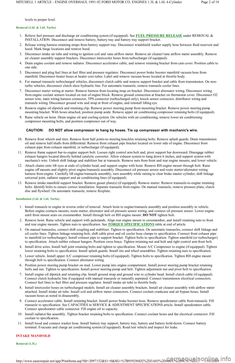
Removal (1.6L & 1.6L Turbo)
1. Relieve fuel pressure and discharge air conditioning system (if equipped). See FUEL PRESSURE RELEASE under REMOVAL &
INSTALLATION. Disconnect and remove battery, battery tray and battery tray support bracket.
2. Release wiring harness retaining straps from battery support tray. Disconnect windshield washer supply hose between fluid reservoir and
hood. Mark hinge locations and remove hood.
3. Disconnect intake air tube and wiring to ignition coil and vane airflow meter. Remove air cleaner/vane airflow meter assembly. Remove
air cleaner assembly support brackets. Disconnect intercooler hoses from turbocharger (if equipped).
4. Drain engine coolant and remove radiator. Disconnect accelerator cable, and remove retaining bracket from cam cover. Position cable to
one side.
5. Disconnect and plug fuel lines at fuel filter and pressure regulator. Disconnect power brake booster manifold vacuum hose from
manifold. Disconnect heater hoses at heater core tubes. Label and remove vacuum hoses located at throttle body.
6. For manual transaxle turbocharged vehicles, disconnect clutch cable and remove support bracket and cable from transmission. On non-
turbo vehicles, disconnect clutch slave hydraulic line. For automatic transaxle, remove transaxle cooler lines.
7. Disconnect starter wiring at starter. Remove harness from locating strap on bracket. Disconnect alternator wiring. Disconnect wiring
from engine coolant sensors located on rear of engine block. Remove ground connection at bracket on thermostat cover. Disconnect O2
sensor wire, main wiring harness connector, TPS connector (turbocharged only), knock sensor connector, distributor wiring and
transaxle wiring. Disconnect ground wire and strap at front of engine, and reinstall lifting eye.
8. Remove engine oil dipstick and retaining clip. Remove power steering pump from mounting bracket. Remove power steering pump
mounting bracket. With hoses attached, position pump aside. Remove upper air conditioning compressor retaining bolts (if equipped).
9. Raise vehicle on hoist. Drain engine oil and cooling system. On vehicles with air conditioning, remove lower air conditioning
compressor mounting bolts, and position compressor out of way.
10. Remove front wheels and tires. Remove front ball joints-to-ste e r in g kn u c kl e s r e t a in in g b o l t s. R e mo ve sp l a sh gu a r d s. Dr a in t ransmission
oil and remove half shafts from differential. Remove front exhaust pipe bracket located on lower side of engine. Disconnect front
exhaust pipe from exhaust manifold, or turbocharger (if equipped).
11. Remove frame support bar-to-engine support bolt. Loosen right control arm bolt and, pivot support bar downward. Disengage rubber
exhaust hangers located directly behind catalytic converter. Allow exhaust system to hang down 6 inches, and support system with
mechanic's wire. Unbolt shift linkage and stabilizer bar at transaxle. Remove nuts from front and rear engine mounts, and lower vehicle.
12. Attach chains onto lift eyes at ends of cylinder head, and support engine with hoist. Remove RH engine mount through bolt. Raise
engine off mounts and slightly pivot engine/transaxle assembly. Disconnect oil pressure sensor and route starter/alternator wiring
harness from engine. Carefully lift engine/transaxle assembly, turn assembly while raising to clear brake master cylinder, shift linkage
universal joint, radiator support and air conditioning lines (if equipped).
13. Remove intake manifold support bracket. Remove gusset plate(s) (if equipped). Remove starter. Remove transaxle-to-engine retaining
bolts. Identify bolts to ensure correct installation. Separate transaxle from engine. On manual transaxle, remove pressure plate, clutch
disc and flywheel. On automatic transaxle, remove flexplate.
Installation (1.6L & 1.6L Turbo)
1. Install transaxle to engine in reverse order of removal. Attach hoist to engine/transaxle assembly and position assembly in vehicle.
Before engine contacts mounts, route starter, alternator and oil pressure sensor wiring, and connect oil pressure sensor. Lower engine
until front mount seats on crossmember. Install through bolt on RH engine mount. DO NOT tighten bolt.
2. Remove hoist. Raise vehicle and support with jackstands. Align rear engine mount to crossmember, and install retaining nuts to front
and rear engine mounts. Tighten nuts to specification. See TORQUE SPECIFICATIONS
table at end of article.
3. On manual transaxles, connect shift coupling and stabilizer. Tighten to specification. On automatic transaxles, connect shift linkage and
oil cooler lines. Tighten linkage retaining bolt, shift cable pivot and oil cooler hose clamps to specification. Connect front exhaust pipe
to manifold (or turbocharger). Install exhaust pipe to support bracket. Tighten bolts to specification. Tighten manifold (or turbocharger)
to specification. Attach rubber exhaust hangers. Position cross brace. Tighten retaining nut and bolt and right control arm front bolt.
4. Install drive axles. Install ball joint retaining bolts and tighten to specification. Mount A/C Compressor to engine (if equipped). Tighten
lower retaining bolts to specification. Install splash guards. Install tire and wheel assemblies. Tighten retaining nuts to specification.
5. Lower vehicle. Install upper A/C compressor retaining bolts (if equipped). Tighten bolts to specification. Tighten RH engine mo u n t
through bolt to specification. Connect alternator wiring.
6. Position power steering pump bracket on stud. Lower pump into engine compartment. Install power steering pump bracket retaining
bolts and nut. Tighten to specification. Install power steering pump and belt. Tighten adjustment nut and pivot bolt to specification.
7. Install engine oil dipstick and retaining clip. Install ground strap and ground wire to cylinder head. Install clutch cable (if equipped).
Connect clutch hydraulic line if equipped with manual transaxle or naturally aspirated. Connect transmission electrical connectors.
Connect fuel lines to fuel filter and pressure regulator. Install intake air tube to throttle body.
8. Install intercooler hoses on turbocharged models. Install air cleaner assembly brackets. Install air cleaner assembly with airflow meter
attached. Install intake air tube. Install coil and airflow meter connectors. Connect coolant crankcase and air bypass hoses. Install
vacuum hoses as noted in disassembly.
9. Connect accelerator cable. Install retaining bracket. Install power brake booster hose. Remove speedometer cable from transaxle. Fill
transaxle to specification. See CAPACITIES in SERVICE & ADJUSTMENT SPECIFICATIONS article. Install speedometer cable.
Connect speedometer cable connector. Fill engine oil to capacity.
10. Install radiator/fan assembly. Tighten bracket retaining bolts to specification. Connect coolant hoses and fan electrical connector. Fill
coolant to specification.
11. Install hood and connect washer hose. Install battery tray support, battery tray, battery and battery hold-down. Connect battery
terminal. Evacuate and charge air conditioning system (if equipped). Road test vehicle and inspect for leaks.
INTAKE MANIFOLD
Removal (1.3L)
CAUT ION: DO NOT allow com pressor to hang by hoses. T ie up com pressor with m echanic's wire.
Page 2 of 19 MITCHELL 1 ARTICLE - ENGINE OVERHAUL 1991-92 FORD MOTOR CO. ENGINES 1.3L & 1.6L 4-Cylinder
3/10/2009 http://www.eautorepair.net/app/PrintItems.asp?S0=2097152&S1=0&SG=%7B959286D2%2D3A85%2D4BFC%2D9C5C%2D
...
Page 138 of 454
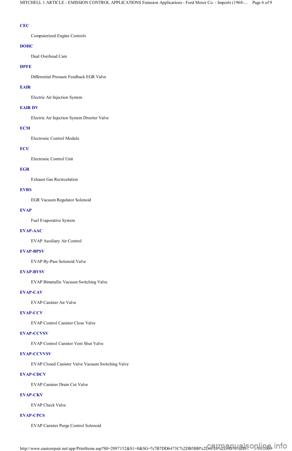
CEC
Computerized Engine Controls
DOHC
Dual Overhead Cam
DPFE
Differential Pressure Feedback EGR Valve
EAIR
Electric Air Injection System
EAIR DV
Electric Air Injection System Diverter Valve
ECM
Electronic Control Module
ECU
Electronic Control Unit
EGR
Exhaust Gas Recirculation
EVRS
EGR Vacuum Regulator Solenoid
EVAP
Fuel Evaporative System
EVAP-AAC
EVAP Auxiliary Air Control
EVAP-BPSV
EVAP By-Pass Solenoid Valve
EVAP-BVSV
EVAP Bimetallic Vacuum Switching Valve
EVAP-CAV
EVAP Canister Air Valve
EVAP-CCV
EVAP Control Canister Close Valve
EVAP-CCVSV
EVAP Control Canister Vent Shut Valve
EVAP-CCVVSV
EVAP Closed Canister Valve Vacuum Switching Valve
EVAP-CDCV
EVAP Canister Drain Cut Valve
EVAP-CKV
EVAP Check Valve
EVAP-CPCS
EVAP Canister Purge Control Solenoid
Page 6 of 9 MITCHELL 1 ARTICLE - EMISSION CONTROL APPLICATIONS Emission Applications - Ford Motor Co. - Imports (1968-
...
3/10/2009 http://www.eautorepair.net/app/PrintItems.asp?S0=2097152&S1=0&SG=%7B7DD6473C%2DB5BB%2D4F20%2D9D70%2D
...
Page 238 of 454
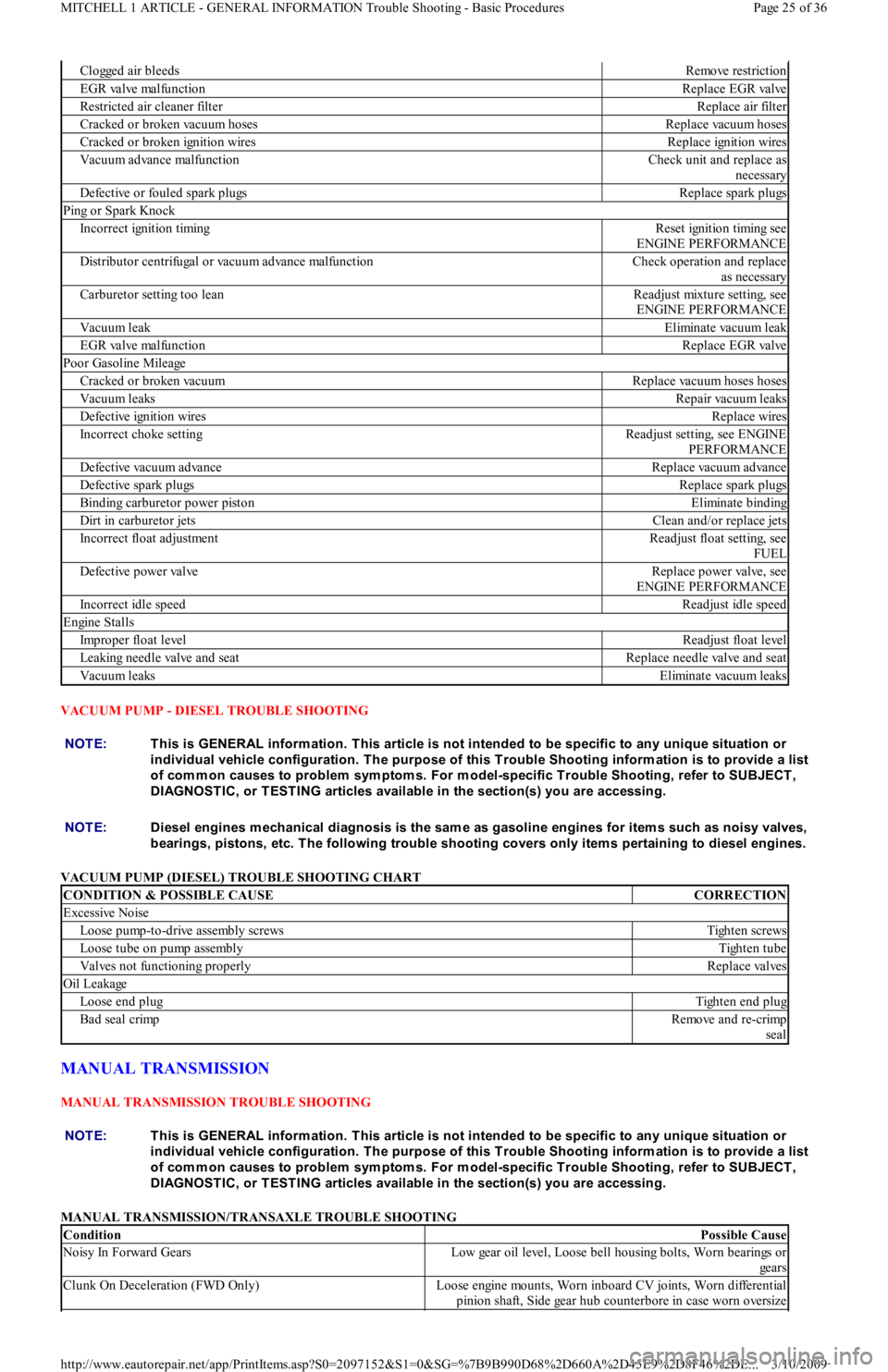
VACUUM PUMP - DIESEL TROUBLE SHOOTING
VACUUM PUMP (DIESEL) TROUBLE SHOOTING CHART
MANUAL TRANSMISSION
MANUAL TRANSMISSION TROUBLE SHOOTING
MANUAL TRANSMISSION/TRANSAXLE TROUBLE SHOOTING
Clogged air bleedsRemove restriction
EGR valve malfunctionReplace EGR valve
Restricted air cleaner filterReplace air filter
Cracked or broken vacuum hosesReplace vacuum hoses
Cracked or broken ignition wiresReplace ignition wires
Vacuum advance malfunctionCheck unit and replace as
necessary
Defective or fouled spark plugsReplace spark plugs
Ping or Spark Knock
Incorrect ignition timingReset ignition timing see
ENGINE PERFORMANCE
Distributor centrifugal or vacuum advance malfunctionCheck operation and replace
as necessary
Carburetor setting too leanReadjust mixture setting, see
ENGINE PERFORMANCE
Vacuum leakEliminate vacuum leak
EGR valve malfunctionReplace EGR valve
Poor Gasoline Mileage
Cracked or broken vacuumReplace vacuum hoses hoses
Vacuum leaksRepair vacuum leaks
Defective ignition wiresReplace wires
Incorrect choke settingReadjust setting, see ENGINE
PERFORMANCE
Defective vacuum advanceReplace vacuum advance
Defective spark plugsReplace spark plugs
Binding carburetor power pistonEliminate binding
Dirt in carburetor jetsClean and/or replace jets
Incorrect float adjustmentReadjust float setting, see
FUEL
Defective power valveReplace power valve, see
ENGINE PERFORMANCE
Incorrect idle speedReadjust idle speed
Engine Stalls
Improper float levelReadjust float level
Leaking needle valve and seatReplace needle valve and seat
Vacuum leaksEliminate vacuum leaks
NOTE:This is GENERAL inform ation. This article is not intended to be specific to any unique situation or
individual vehicle configuration. T he purpose of this T rouble Shooting inform ation is to provide a list
of com m on causes to problem sym ptom s. For m odel-specific T rouble Shooting, refer to SUBJECT ,
DIAGNOST IC, or T EST ING articles available in the section(s) you are accessing.
NOTE:Diesel engines m echanical diagnosis is the sam e as gasoline engines for item s such as noisy valves,
bearings, pistons, etc. T he following trouble shooting covers only item s pertaining to diesel engines.
CONDITION & POSSIBLE CAUSECORRECTION
Excessive Noise
Loose pump-to-drive assembly screwsTighten screws
Loose tube on pump assemblyTighten tube
Valves not functioning properlyReplace valves
Oil Leakage
Loose end plugTighten end plug
Bad seal crimpRemove and re-crimp
seal
NOTE:This is GENERAL inform ation. This article is not intended to be specific to any unique situation or
individual vehicle configuration. T he purpose of this T rouble Shooting inform ation is to provide a list
of com m on causes to problem sym ptom s. For m odel-specific T rouble Shooting, refer to SUBJECT ,
DIAGNOST IC, or T EST ING articles available in the section(s) you are accessing.
ConditionPossible Cause
Noisy In Forward GearsLow gear oil level, Loose bell housing bolts, Worn bearings or
gears
Clunk On Deceleration (FWD Only)Loose engine mounts, Worn inboard CV joints, Worn differential
pinion shaft, Side gear hub counterbore in case worn oversize
Page 25 of 36 MITCHELL 1 ARTICLE - GENERAL INFORMATION Trouble Shooting - Basic Procedures
3/10/2009 http://www.eautorepair.net/app/PrintItems.asp?S0=2097152&S1=0&SG=%7B9B990D68%2D660A%2D45E9%2D8F46%2DE
...
Page 241 of 454
A "howling" or "whining" noise from the ring and pinion gear can be caused by an improper gear pattern, gear damage, or improper bearing
preload. It can occur at various speeds and driving conditions, or it can be continuous.
Before disassembling axle to diagnose and correct gear ke sure that tires, exhaust, and vehicle trim have been checked as possible causes.
Chuckle
This is a particular rattling noise that sounds like a stick against the spokes of a spinning bicycle wheel. It occurs while decelerating from 40
MPH and usually can be heard until vehicle comes to a complete stop. The frequency varies with the speed of the vehicle.
A chuckle that occurs on the driving phase is usually caused ive clearance due to differential gear wear, or by a damaged tooth on the coast
side of the pinion or ring gear. Even a very small tooth nick or a ridge on the edge of a gear tooth is enough the cause the noise.
This condition can be corrected simply by cleaning the gear tooth nick or ridge with a small grinding wheel. If either gear is damaged or scored
badly, the gear set must be replaced. If metal has broken loose, the carrier and housing must be cleaned to remove particles that could cause
damage.
Knock
This is very similar to a chuckle, though it may be louder, and occur on acceleration or deceleration. Knock can be caused by a gear tooth that
is damaged on the drive side of the ring and pinion gears. Ring gear bolts that are hitting the carrier casting can cause knock. Knock can also be
due to excessive end play in the axle shafts.
Clunk
Clunk is a metallic noise heard when an automatic transmission is engaged in Reverse or Drive, or when throttle is applied or released. It is
caused by backlash somewhere in the driveline, but not necessarily in the axle. To determine whether driveline clunk is caused by the axle,
check the total axle backlash as follows:
1. Raise vehicle on a frame or twinpost hoist so that drive wheels are free. Clamp a bar between axle companion flange and a part of the
frame or body so that flange cannot move.
2. On conventional drive axles, lock the left wheel to keep it from turning. On all models, turn the right wheel slowly until it is felt to be in
Drive condition. Hold a chalk marker on side of tire about 12" from center of wheel. Turn wheel in the opposite direction until it is
again felt to be in Drive condition.
3. Measure the length of the chalk mark, which is the total axle backlash. If backlash is one inch or less, drive axle is not the source of
clunk noise.
Bearing Whine
Bearing whine is a high-pitched sound similar to a whistle. It is usually caused by malfunctioning pinion bearings. Pinion bearings operate at
drive shaft speed. Roller wheel bearings may whine in a similar manner if they run completely dry of lubricant. Bearing noise will occur at all
driving speeds. This distinguishes it from gear whine, which usually comes and goes as speed changes.
Bearing Rumble
Bearing rumble sounds like marbles being tumbled. It is usually caused by a malfunctioning wheel bearing. The lower pitch is because the
wheel bearing turns at only about 1/3 of drive shaft speed.
Chatter On Turns
This is a condition where the entire front or rear of vehicle vibrates when vehicle is moving. The vibration is plainly felt as well as heard. Extra
differential thrust washers installed during axle repair can cause a condition of partial lock-up that creates this chatter.
Axle Shaft Noise
Axle shaft noise is similar to gear noise and pinion bearing whine. Axle shaft bearing noise will normally distinguish itself from gear noise by
occurring in all driving modes (Drive, cruise, coast and float), and will persist with transmission in Neutral while vehicle is moving at problem
speed.
If vehicle displays this noise condition, remove suspect parts, replace wheel seals and install a new set of bearings. Re-evaluate vehicle for
noise before removing any internal components.
Vibration
Vibration is a high-frequency trembling, shaking or grinding condition (felt or heard) that may be constant or variable in level and can occur
during the total operating speed range of the vehicle.
The types of vibrations that can be felt in the vehicle can d into 3 main groups:
Vibrations of various unbalanced rotating parts of the vehicle.
Resonance vibrations of the body and frame structures caused by rotating of unbalanced parts.
Tip-in moans of resonance vibrations from stressed engine or exhaust system mounts or driveline flexing modes.
DRIVE AXLE - RWD TROUBLE SHOOTING
NOTE:This is GENERAL inform ation. This article is not intended to be specific to any unique situation or
individual vehicle configuration. T he purpose of this T rouble Shooting inform ation is to provide a list
of com m on causes to problem sym ptom s. For m odel-specific T rouble Shooting, refer to SUBJECT ,
DIAGNOST IC, or T EST ING articles available in the section(s) you are accessing. For definitions of listed
noises or sounds, see DRIVE AXLE
- NOISE DIAGNOSIS under POWERTRAIN.
Page 28 of 36 MITCHELL 1 ARTICLE - GENERAL INFORMATION Trouble Shooting - Basic Procedures
3/10/2009 http://www.eautorepair.net/app/PrintItems.asp?S0=2097152&S1=0&SG=%7B9B990D68%2D660A%2D45E9%2D8F46%2DE
...
Page 242 of 454
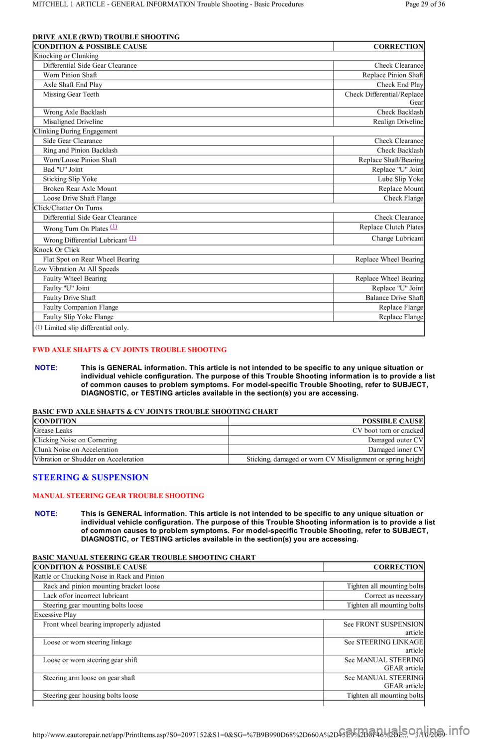
DRIVE AXLE (RWD) TROUBLE SHOOTING
FWD AXLE SHAFTS & CV JOINTS TROUBLE SHOOTING
BASIC FWD AXLE SHAFTS & CV JOINTS TROUBLE SHOOTING CHART
STEERING & SUSPENSION
MANUAL STEERING GEAR TROUBLE SHOOTING
BASIC MANUAL STEERING GEAR TROUBLE SHOOTING CHART
CONDITION & POSSIBLE CAUSECORRECTION
Knocking or Clunking
Differential Side Gear ClearanceCheck Clearance
Worn Pinion ShaftReplace Pinion Shaft
Axle Shaft End PlayCheck End Play
Missing Gear TeethCheck Differential/Replace
Gear
Wrong Axle BacklashCheck Backlash
Misaligned DrivelineRealign Driveline
Clinking During Engagement
Side Gear ClearanceCheck Clearance
Ring and Pinion BacklashCheck Backlash
Worn/Loose Pinion ShaftReplace Shaft/Bearing
Bad "U" JointReplace "U" Joint
Sticking Slip YokeLube Slip Yoke
Broken Rear Axle MountReplace Mount
Loose Drive Shaft FlangeCheck Flange
Click/Chatter On Turns
Differential Side Gear ClearanceCheck Clearance
Wrong Turn On Plates (1)Replace Clutch Plates
Wrong Differential Lubricant (1)Change Lubricant
Knock Or Click
Flat Spot on Rear Wheel BearingReplace Wheel Bearing
Low Vibration At All Speeds
Faulty Wheel BearingReplace Wheel Bearing
Faulty "U" JointReplace "U" Joint
Faulty Drive ShaftBalance Drive Shaft
Faulty Companion FlangeReplace Flange
Faulty Slip Yoke FlangeReplace Flange
(1)Limited slip differential only.
NOTE:This is GENERAL inform ation. This article is not intended to be specific to any unique situation or
individual vehicle configuration. T he purpose of this T rouble Shooting inform ation is to provide a list
of com m on causes to problem sym ptom s. For m odel-specific T rouble Shooting, refer to SUBJECT ,
DIAGNOST IC, or T EST ING articles available in the section(s) you are accessing.
CONDITIONPOSSIBLE CAUSE
Grease LeaksCV boot torn or cracked
Clicking Noise on CorneringDamaged outer CV
Clunk Noise on AccelerationDamaged inner CV
Vibration or Shudder on AccelerationSticking, damaged or worn CV Misalignment or spring height
NOTE:This is GENERAL inform ation. This article is not intended to be specific to any unique situation or
individual vehicle configuration. T he purpose of this T rouble Shooting inform ation is to provide a list
of com m on causes to problem sym ptom s. For m odel-specific T rouble Shooting, refer to SUBJECT ,
DIAGNOST IC, or T EST ING articles available in the section(s) you are accessing.
CONDITION & POSSIBLE CAUSECORRECTION
Rattle or Chucking Noise in Rack and Pinion
Rack and pinion mounting bracket looseTighten all mounting bolts
Lack of/or incorrect lubricantCorrect as necessary
Steering gear mounting bolts looseTighten all mounting bolts
Excessive Play
Front wheel bearing improperly adjustedSee FRONT SUSPENSION
article
Loose or worn steering linkageSee STEERING LINKAGE
article
Loose or worn steering gear shiftSee MANUAL STEERING
GEAR article
Steering arm loose on gear shaftSee MANUAL STEERING
GEAR article
Steering gear housing bolts looseTighten all mounting bolts
Page 29 of 36 MITCHELL 1 ARTICLE - GENERAL INFORMATION Trouble Shooting - Basic Procedures
3/10/2009 http://www.eautorepair.net/app/PrintItems.asp?S0=2097152&S1=0&SG=%7B9B990D68%2D660A%2D45E9%2D8F46%2DE
...
Page 253 of 454
Back To Article
GENERAL INFORMATION
Drive Axle Noise Diagnosis
* PLEASE READ THIS FIRST *
UNRELATED NOISES
Some driveline trouble symptoms are also common to the engine, transmission, wheel bearings, tires and other parts of the vehicle. Make sure
that cause of trouble actually is in the drive axle before adjusting, repairing, or replacing any parts.
NON-DRIVE AXLE NOISES
A few conditions can sound just like drive axle noise and have to be considered in pre-diagnosis. The 4 most common noises are exhaust, tires,
CV/universal joints and trim moldings.
In certain conditions, the pitch of exhaust gases may sound like gear whine. At other times, it may be mistaken for a wheel bearing rumble.
Tires, especially radial and snow tires, can have a high-pitched tread whine or roar, similar to gear noise. Also, some non-standard tires with an
unusual tread construction may emit a roar or whine.
Defective CV/universal joints may cause clicking noises or excessive driveline play that can be improperly diagnosed as drive axle problems.
Trim and moldings can also cause a whistling or whining noise. Ensure that none of these components are causing the noise before
disassembling the drive axle.
GEAR NOISE
A "howling" or "whining" noise from the ring and pinion gear can be caused by an improper gear pattern, gear damage, or improper bearing
preload. It can occur at various speeds and driving conditions, or it can be continuous.
Before disassembling axle to diagnose and correct gear noise, make sure that tires, exhaust, and vehicle trim have been checked as possible
causes.
CHUCKLE
This is a particular rattling noise that sounds like a stick against the spokes of a spinning bicycle wheel. It occurs while decelerating from 40
MPH and usually can be heard until vehicle comes to a complete stop. The frequency varies with the speed of the vehicle.
A chuckle that occurs on the driving phase is usually caused by excessive clearance due to differential gear wear, or by a damaged tooth on the
coast side of the pinion or ring gear. Even a very small tooth nick or a ridge on the edge of a gear tooth is enough to cause the noise.
This condition can be corrected simply by cleaning the gear tooth nick or ridge with a small grinding wheel. If either gear is damaged or scored
badly, the gear set must be replaced. If metal has broken loose, the carrier and housing must be cleaned to remove particles that could cause
damage.
KNOCK
This is very similar to a chuckle, though it may be louder, and occur on acceleration of deceleration. Knock can be caused by a gear tooth that
is damaged on the drive side of the ring and pinion gears. Ring gear bolts that are hitting the carrier casting can cause knock. Knock can also be
due to excessive end play in the axle shafts. NOTE:This is GENERAL inform ation. This article is not intended to be specific to any unique situation or
individual vehicle configuration. For m odel-specific inform ation see appropriate articles where
available.
NOTE:This is GENERAL inform ation. This article is not intended to be specific to any unique situation or
individual vehicle configuration. For m odel-specific inform ation see appropriate articles where
available.
NOTE:This is GENERAL inform ation. This article is not intended to be specific to any unique situation or
individual vehicle configuration. For m odel-specific inform ation see appropriate articles where
available.
NOTE:This is GENERAL inform ation. This article is not intended to be specific to any unique situation or
individual vehicle configuration. For m odel-specific inform ation see appropriate articles where
available.
NOTE:This is GENERAL inform ation. This article is not intended to be specific to any unique situation or
individual vehicle configuration. For m odel-specific inform ation see appropriate articles where
available.
NOTE:This is GENERAL inform ation. This article is not intended to be specific to any unique situation or
individual vehicle configuration. For m odel-specific inform ation see appropriate articles where
available.
Page 1 of 2 MITCHELL 1 ARTICLE - GENERAL INFORMATION Drive Axle Noise Diagnosis
3/10/2009 http://www.eautorepair.net/app/PrintItems.asp?S0=2097152&S1=0&SG=%7B9B990D68%2D660A%2D45E9%2D8F46%2DE
...
Page 254 of 454
CLUNK
Clunk is a metallic noise heard when an automatic transmission is engaged in Reverse or Drive, or when throttle is applied or released. It is
caused by backlash somewhere in the driveline, but not necessarily in the axle. To determine whether driveline clunk is caused by the axle,
check the total axle backlash as follows:
1. Raise vehicle on a frame or twinpost hoist so that drive wheels are free. Clamp a bar between axle companion flange and a part of the
frame or body so that flange cannot move.
2. On conventional drive axles, lock the left wheel to keep it from turning. On all models, turn the right wheel slowly until it is felt to be in
drive condition. Hold a chalk marker on side of tire about 12" from center of wheel. Turn wheel in the opposite direction until it is again
felt to be in drive condition.
3. Measure the length of the chalk mark, which is the total axle backlash. If backlash is one inch or less, clunk will not be eliminated by
overhauling drive axle.
BEARING WHINE
Bearing whine is a high-pitched sound similar to a whistle. It is usually caused by malfunctioning pinion bearings. Pinion bearings operate at
driveshaft speed. Roller wheel bearings may whine in a similar manner if they run completely dry of lubricant. Bearing noise will occur at all
driving speeds. This distinguishes it from gear whine, which usually comes and goes as speed changes.
BEARING RUMBLE
Bearing rumble sounds like marbles being tumbled. It is usually caused by a malfunctioning wheel bearing. The lower pitch is because the
wheel bearing turns at only about 1/3 of driveshaft speed.
CHATTER ON TURNS
This is a condition where the whole front or rear vibrates when vehicle is moving. The vibration is easily felt and heard. Extra differential
thrust washers installed during axle repair can cause a condition of partial lock-up that creates the chatter.
AXLE SHAFT NOISE
Axle shaft noise is similar to gear noise and pinion bearing whine. Axle shaft bearing noise will normally distinguish itself from gear noise by
occurring in all driving modes. Noise will persist with transmission in neutral while vehicle is moving at problem speed.
If vehicle displays this noise condition, remove suspect axle shafts and replace axle bearings. Re-evaluate vehicle for noise before removing
any internal components.
VIB R AT ION
Vibration is a high-frequency trembling, shaking or grinding condition (felt or heard) that may be constant or variable in level and con occur
during the total operating speed range of the vehicle.
The types of vibrations that can be felt in the vehicle can be divided into 3 main groups:
Vibrations of various unbalanced rotating parts of the vehicle.
Resonance vibrations of the body and frame structures caused by rotating of unbalance parts.
Tip-in moans of resonance vibrations from stressed engine or exhaust system mounts or driveline flexing modes. NOTE:This is GENERAL inform ation. This article is not intended to be specific to any unique situation or
individual vehicle configuration. For m odel-specific inform ation see appropriate articles where
available.
NOTE:This is GENERAL inform ation. This article is not intended to be specific to any unique situation or
individual vehicle configuration. For m odel-specific inform ation see appropriate articles where
available.
NOTE:This is GENERAL inform ation. This article is not intended to be specific to any unique situation or
individual vehicle configuration. For m odel-specific inform ation see appropriate articles where
available.
NOTE:This is GENERAL inform ation. This article is not intended to be specific to any unique situation or
individual vehicle configuration. For m odel-specific inform ation see appropriate articles where
available.
NOTE:This is GENERAL inform ation. This article is not intended to be specific to any unique situation or
individual vehicle configuration. For m odel-specific inform ation see appropriate articles where
available.
NOTE:This is GENERAL inform ation. This article is not intended to be specific to any unique situation or
individual vehicle configuration. For m odel-specific inform ation see appropriate articles where
available.
Copyr ight 2009 Mitchell Repair Information Company, LLC. All Rights Reserved.
Article GUID: A00002193
Page 2 of 2 MITCHELL 1 ARTICLE - GENERAL INFORMATION Drive Axle Noise Diagnosis
3/10/2009 http://www.eautorepair.net/app/PrintItems.asp?S0=2097152&S1=0&SG=%7B9B990D68%2D660A%2D45E9%2D8F46%2DE
...
Page 305 of 454
Back To Article
GENERAL INFORMATION
Manual Transmission Trouble Shooting
* PLEASE READ THIS FIRST *
INTRODUCTION
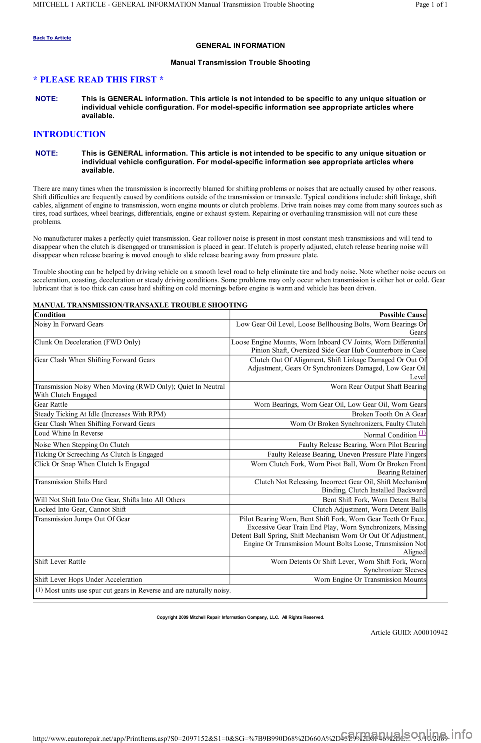
There are many times when the transmission is incorrectly blamed for shifting problems or noises that are actually caused by other reasons.
Shift difficulties are frequently caused by conditions outside of the transmission or transaxle. Typical conditions include: shift linkage, shift
cables, alignment of engine to transmission, worn engine mounts or clutch problems. Drive train noises may come from many sources such as
tires, road surfaces, wheel bearings, differentials, engine or exhaust system. Repairing or overhauling transmission will not cure these
problems.
No manufacturer makes a perfectly quiet transmission. Gear rollover noise is present in most constant mesh transmissions and will tend to
disappear when the clutch is disengaged or transmission is placed in gear. If clutch is properly adjusted, clutch release bearing noise will
disappear when release bearing is moved enough to slide release bearing away from pressure plate.
Trouble shooting can be helped by driving vehicle on a smooth level road to help eliminate tire and body noise. Note whether noise occurs on
acceleration, coasting, deceleration or steady driving conditions. Some problems may only occur when transmission is either hot or cold. Gear
lubricant that is too thick can cause hard shifting on cold mornings before engine is warm and vehicle has been driven.
MANUAL TRANSMISSION/TRANSAXLE TROUBLE SHOOTING NOTE:This is GENERAL inform ation. This article is not intended to be specific to any unique situation or
individual vehicle configuration. For m odel-specific inform ation see appropriate articles where
available.
NOTE:This is GENERAL inform ation. This article is not intended to be specific to any unique situation or
individual vehicle configuration. For m odel-specific inform ation see appropriate articles where
available.
ConditionPossible Cause
Noisy In Forward GearsLow Gear Oil Level, Loose Bellhousing Bolts, Worn Bearings Or
Gears
Clunk On Deceleration (FWD Only)Loose Engine Mounts, Worn Inboard CV Joints, Worn Differential
Pinion Shaft, Oversized Side Gear Hub Counterbore in Case
Gear Clash When Shifting Forward GearsClutch Out Of Alignment, Shift Linkage Damaged Or Out Of
Adjustment, Gears Or Synchronizers Damaged, Low Gear Oil
Level
Transmission Noisy When Moving (RWD Only); Quiet In Neutral
With Clutch EngagedWorn Rear Output Shaft Bearing
Gear RattleWorn Bearings, Worn Gear Oil, Low Gear Oil, Worn Gears
Steady Ticking At Idle (Increases With RPM)Broken Tooth On A Gear
Gear Clash When Shifting Forward GearsWorn Or Broken Synchronizers, Faulty Clutch
Loud Whine In ReverseNormal Condition (1)
Noise When Stepping On ClutchFaulty Release Bearing, Worn Pilot Bearing
Ticking Or Screeching As Clutch Is EngagedFaulty Release Bearing, Uneven Pressure Plate Fingers
Click Or Snap When Clutch Is EngagedWorn Clutch Fork, Worn Pivot Ball, Worn Or Broken Front
Bearing Retainer
Transmission Shifts HardClutch Not Releasing, Incorrect Gear Oil, Shift Mechanism
Binding, Clutch Installed Backward
Will Not Shift Into One Gear, Shifts Into All OthersBent Shift Fork, Worn Detent Balls
Locked Into Gear, Cannot ShiftClutch Adjustment, Worn Detent Balls
Transmission Jumps Out Of GearPilot Bearing Worn, Bent Shift Fork, Worn Gear Teeth Or Face,
Excessive Gear Train End Play, Worn Synchronizers, Missing
Detent Ball Spring, Shift Mechanism Worn Or Out Of Adjustment,
Engine Or Transmission Mount Bolts Loose, Transmission Not
Aligned
Shift Lever RattleWorn Detents Or Shift Lever, Worn Shift Fork, Worn
Synchronizer Sleeves
Shift Lever Hops Under AccelerationWorn Engine Or Transmission Mounts
(1)Most units use spur cut gears in Reverse and are naturally noisy.
Copyr ight 2009 Mitchell Repair Information Company, LLC. All Rights Reserved.
Article GUID: A00010942
Page 1 of 1 MITCHELL 1 ARTICLE - GENERAL INFORMATION Manual Transmission Trouble Shooting
3/10/2009 http://www.eautorepair.net/app/PrintItems.asp?S0=2097152&S1=0&SG=%7B9B990D68%2D660A%2D45E9%2D8F46%2DE
...
Page 409 of 454
Back To Article
1988-94 AUT OMAT IC T RANSMISSIONS
Ford ATX Overhaul
APPLICATION
APPLICATION
DESCRIPTION
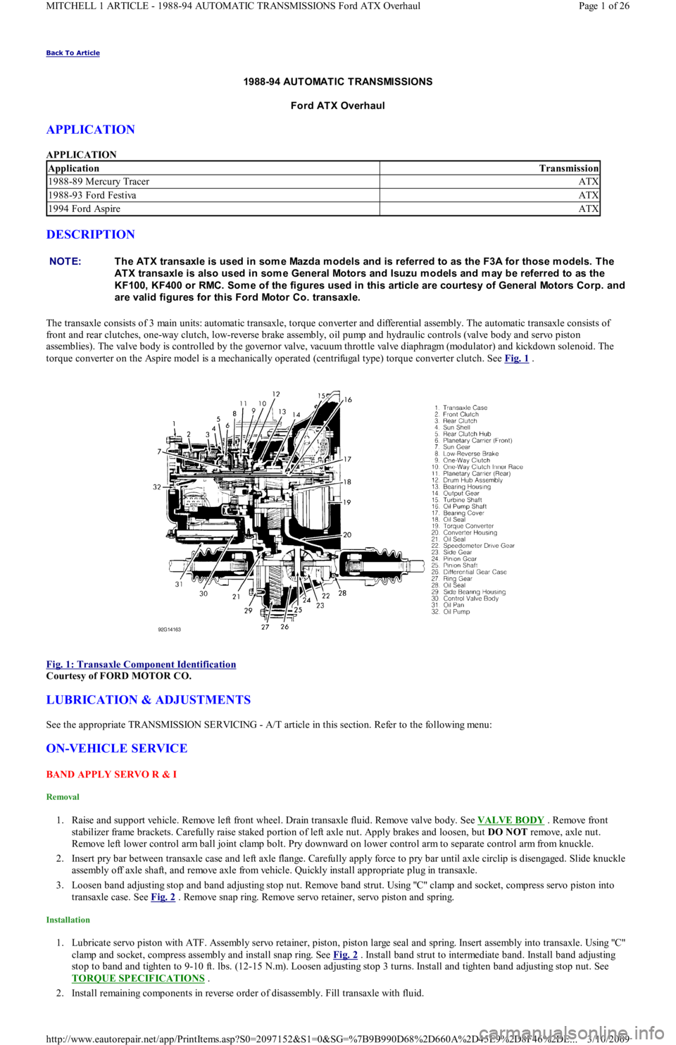
The transaxle consists of 3 main units: automatic transaxle, torque converter and differential assembly. The automatic transaxle consists of
front and rear clutches, one-way clutch, low-reverse brake assembly, oil pump and hydraulic controls (valve body and servo piston
assemblies). The valve body is controlled by the governor valve, vacuum throttle valve diaphragm (modulator) and kickdown solenoid. The
torque converter on the Aspire model is a mechanically operated (centrifugal type) torque converter clutch. See Fig. 1
.
Fig. 1: Transaxle Component Identification
Courtesy of FORD MOTOR CO.
LUBRICATION & ADJUSTMENTS
See the appropriate TRANSMISSION SERVICING - A/T article in this section. Refer to the following menu:
ON-VEHICLE SERVICE
BAND APPLY SERVO R & I
Removal
1. Raise and support vehicle. Remove left front wheel. Drain transaxle fluid. Remove valve body. See VALVE BODY . Remove front
stabilizer frame brackets. Carefully raise staked portion of left axle nut. Apply brakes and loosen, but DO NOT remove, axle nut.
Remove left lower control arm ball joint clamp bolt. Pry downward on lower control arm to separate control arm from knuckle.
2. Insert pry bar between transaxle case and left axle flange. Carefully apply force to pry bar until axle circlip is disengaged. Slide knuckle
assembly off axle shaft, and remove axle from vehicle. Quickly install appropriate plug in transaxle.
3. Loosen band adjusting stop and band adjusting stop nut. Remove band strut. Using "C" clamp and socket, compress servo piston into
transaxle case. See Fig. 2
. Remove snap ring. Remove servo retainer, servo piston and spring.
Installation
1. Lubricate servo piston with ATF. Assembly servo retainer, piston, piston large seal and spring. Insert assembly into transaxle. Usin g "C"
clamp and socket, compress assembly and install snap ring. See Fig. 2
. Install band strut to intermediate band. Install band adjusting
stop to band and tighten to 9-10 ft. lbs. (12-15 N.m). Loosen adjusting stop 3 turns. Install and tighten band adjusting stop nut. See
TORQUE SPECIFICATIONS
.
2. Install remaining components in reverse order of disassembly. Fill transaxle with fluid.
ApplicationTransmission
1988-89 Mercury TracerATX
1988-93 Ford FestivaATX
1994 Ford AspireATX
NOTE:T he AT X transaxle is used in som e Mazda m odels and is referred to as the F3A for those m odels. T he
AT X transaxle is also used in som e General Motors and Isuzu m odels and m ay be referred to as the
KF100, KF400 or RMC. Som e of the figures used in this article are courtesy of General Motors Corp. and
are valid figures for this Ford Motor Co. transaxle.
Page 1 of 26 MITCHELL 1 ARTICLE - 1988-94 AUTOMATIC TRANSMISSIONS Ford ATX Overhaul
3/10/2009 http://www.eautorepair.net/app/PrintItems.asp?S0=2097152&S1=0&SG=%7B9B990D68%2D660A%2D45E9%2D8F46%2DE
...