brake rotor FORD FESTIVA 1991 Service Manual
[x] Cancel search | Manufacturer: FORD, Model Year: 1991, Model line: FESTIVA, Model: FORD FESTIVA 1991Pages: 454, PDF Size: 9.53 MB
Page 31 of 454
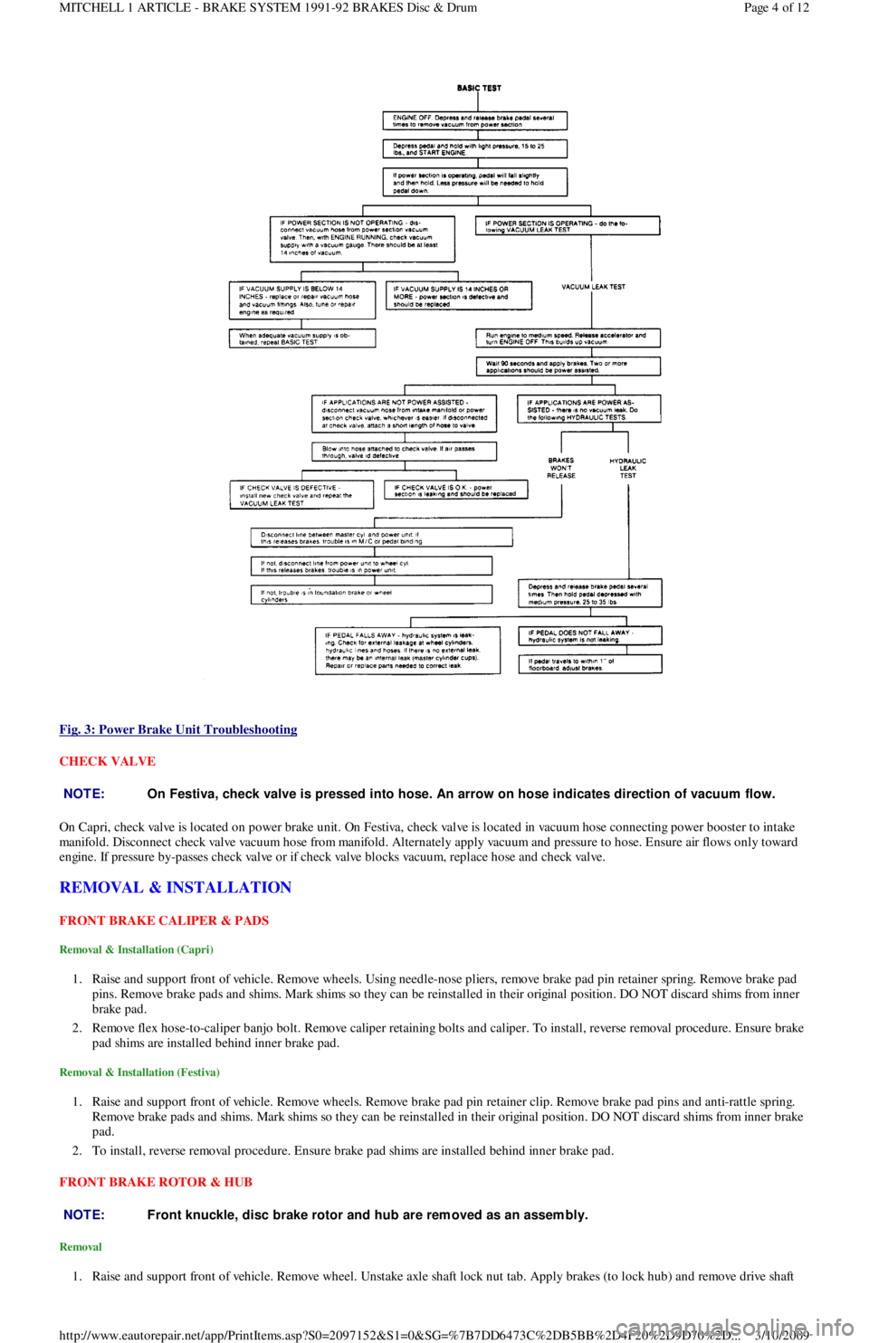
Fig. 3: Power Brake Unit Troubleshooting
CHECK VALVE
On Capri, check valve is located on power brake unit. On Festiva, check valve is located in vacuum hose connecting power booster to intake
manifold. Disconnect check valve vacuum hose from manifold. Alternately apply vacuum and pressure to hose. Ensure air flows only toward
engine. If pressure by-passes check valve or if check valve blocks vacuum, replace hose and check valve.
REMOVAL & INSTALLATION
FRONT BRAKE CALIPER & PADS
Removal & Installation (Capri)
1. Raise and support front of vehicle. Remove wheels. Using needle-nose pliers, remove brake pad pin retainer spring. Remove brake pad
pins. Remove brake pads and shims. Mark shims so they can be reinstalled in their original position. DO NOT discard shims from inner
brake pad.
2. Remove flex hose-to-caliper banjo bolt. Remove caliper retaining bolts and caliper. To install, reverse removal procedure. Ensure brake
pad shims are installed behind inner brake pad.
Removal & Installation (Festiva)
1. Raise and support front of vehicle. Remove wheels. Remove brake pad pin retainer clip. Remove brake pad pins and anti-rattle spring.
Remove brake pads and shims. Mark shims so they can be reinstalled in their original position. DO NOT discard shims from inner brake
pad.
2. To install, reverse removal procedure. Ensure brake pad shims are installed behind inner brake pad.
FRONT BRAKE ROTOR & HUB
Removal
1. Raise and support front of vehicle. Remove wheel. Unstake axle shaft lock nut tab. Apply brakes (to lock hub) and remove drive shaft
NOTE:On Festiva, check valve is pressed into hose. An arrow on hose indicates direction of vacuum flow.
NOTE:Front knuckle, disc brake rotor and hub are rem oved as an assem bly.
Page 4 of 12 MITCHELL 1 ARTICLE - BRAKE SYSTEM 1991-92 BRAKES Disc & Drum
3/10/2009 http://www.eautorepair.net/app/PrintItems.asp?S0=2097152&S1=0&SG=%7B7DD6473C%2DB5BB%2D4F20%2D9D70%2D
...
Page 32 of 454
lock nut. Discard axle lock nut. Separate tie rod end from knuckle.
2. Disconnect brake hose from strut (if necessary). Remove brake caliper assembly from knuckle and wire out of way. Remove nuts and
bolts holding ball joint and strut to knuckle assembly.
3. Remove knuckle assembly from ball joint and drive shaft. If binding occurs, use a dual-jawed puller to force knuckle/hub/rotor assembly
off drive axle shaft.
4. Using a puller, separate knuckle from wheel hub. Retain original outer bearing preload spacer to maintain bearing preload setting. If
replacing bearing, change spacer to maintain proper bearing preload (if necessary). See FRONT WHEEL BEARINGS under REMOVAL
& INSTALLATION. Scribe match marks between hub and rotor assembly. Remove rotor-to-hub bolts. Separate hub from rotor.
Installation
Align marks and install rotor on hub. Press knuckle and preload spacer into wheel hub assembly. To complete installation, reverse removal
procedure. Tighten axle shaft lock nut to 117-175 ft. lbs. (159-237 N.m).
REAR BRAKE CALIPER & PADS
Removal (Capri)
1. Raise and support vehicle. Remove tire and wheel assembly. Using needle-nose pliers, remove parking brake return spring. Loosen
parking brake cable housing adjusting nut. Remove cable housing from bracket on lower control arm. Loosen parking brake cable
bracket-to-caliper attaching bolt. Remove parking brake cable from caliper.
2. Remove lower caliper retaining bolt. Pivot caliper upward on upper caliper guide pin. Remove brake pad retaining spring, pads and
shims. If replacing rear brake pads only, reverse removal procedure to install. If removing caliper, proceed to next step.
3. Remove attaching clip from brake flex hose. Remove flex hose banjo bolt from caliper and discard copper washers. Remove lower
caliper retaining bolt. Using a cold chisel, remove upper caliper guide pin dust cap. Using an Allen wrench, remove upper caliper guide
pin. Lift caliper off rotor.
Installation
1. To install, fit brake pads and shims into caliper anchor plate. Remove upper guide pin and lower guide pin bushing from caliper.
Remove guide pin and guide pin bushing dust boots. Lubricate upper guide pin and lower guide pin bushing with Disc Brake Caliper
Slide Grease (D7AZ-19590-A).
2. To complete installation, reverse removal procedure. To fit caliper over new brake pads, it may be necessary to rotate caliper piston into
caliper bore. Use NEW copper washers on flex hose. Bleed brakes, and then pump brake pedal several times to seat pads.
REAR BRAKE ROTOR
Removal & Installation (Capri)
See REAR WHEEL BEARINGS under REMOVAL & INSTALLATION.
REAR BRAKE SHOES
Removal & Installation (Festiva)
Remove brake drum. Remove hold-down springs. Remove return springs. Remove self adjuster. See Fig. 8 . To install, reverse removal
procedure. Apply brake grease to all shoe contact points. See REAR BRAKE SHOES under ADJUSTMENTS.
REAR WHEEL CYLINDER
Removal & Installation (Festiva)
Remove rear brake shoes. Disconnect brake line from wheel cylinder. Remove wheel cylinder. To install, reverse removal procedure. Bleed
brake system.
MASTER BRAKE CYLINDER
Removal
Disconnect low fluid level sensor wiring (if equipped). Drain some brake fluid from reservoir. Disconnect brake lines from master cylinder.
Cap lines and master cylinder ports. Remove attaching nuts and master cylinder.
Installation
To install, reverse removal procedure. Fill master cylinder to proper level and bleed hydraulic system (if necessary).
POWER BRAKE UNIT
Removal & Installation
Remove master cylinder. Disconnect vacuum line. Remove clevis pin at brake pedal. Remove power brake unit. To install, reverse removal
procedure.
FRONT WHEEL BEARINGS NOTE:Hub and rotor are a m atched and balanced assem bly. Before rem oving rotor, locate paint or etch
m ark indicating proper hub-to-rotor alignm ent. If m arks are not present, m ark hub and rotor for
assem bly alignm ent. Failure to properly align hub and rotor can result in an im balance condition.
Page 5 of 12 MITCHELL 1 ARTICLE - BRAKE SYSTEM 1991-92 BRAKES Disc & Drum
3/10/2009 http://www.eautorepair.net/app/PrintItems.asp?S0=2097152&S1=0&SG=%7B7DD6473C%2DB5BB%2D4F20%2D9D70%2D
...
Page 33 of 454
Removal
Remove rotor and hub assembly from steering knuckle. Separate rotor, knuckle and hub. See FRONT BRAKE ROTOR & HUB under
REMOVAL & INSTALLATION. Press outer bearing from hub using Bearing Splitter (D84L-1123-A) and Shaft Protector (D80L-625-2).
Remove and discard outer grease seal. Pry inner wheel bearing grease seal from steering knuckle using a large screwdriver. Discard seal.
R e mo ve in n e r b e a r in g.
Bearing Preload
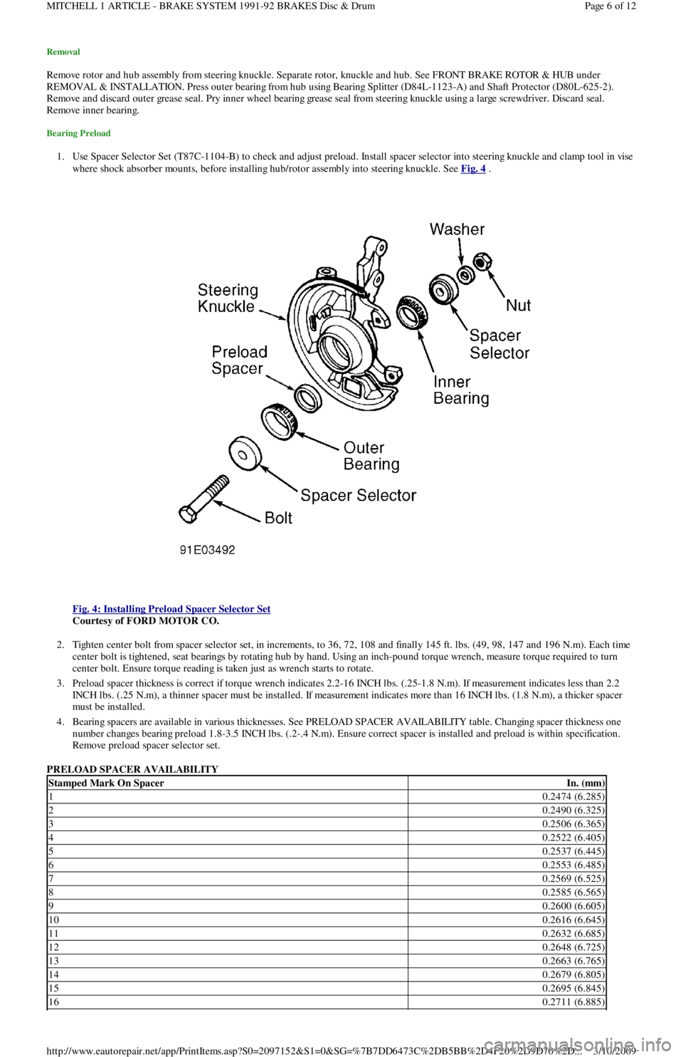
1. Use Spacer Selector Set (T87C-1104-B) to check and adjust preload. Install spacer selector into steering knuckle and clamp tool in vise
where shock absorber mounts, before installing hub/rotor assembly into steering knuckle. See Fig. 4
.
Fig. 4: Installing Preload Spacer Selector Set
Courtesy of FORD MOTOR CO.
2. Tighten center bolt from spacer selector set, in increments, to 36, 72, 108 and finally 145 ft. lbs. (49, 98, 147 and 196 N.m). Each time
center bolt is tightened, seat bearings by rotating hub by hand. Using an inch-pound torque wrench, measure torque required to turn
center bolt. Ensure torque reading is taken just as wrench starts to rotate.
3. Preload spacer thickness is correct if torque wrench indicates 2.2-16 INCH lbs. (.25-1.8 N.m). If measurement indicates less than 2.2
INCH lbs. (.25 N.m), a thinner spacer must be installed. If measurement indicates more than 16 INCH lbs. (1.8 N.m), a thicker spacer
must be installed.
4. Bearing spacers are available in various thicknesses. See PRELOAD SPACER AVAILABILITY table. Changing spacer thickness one
number changes bearing preload 1.8-3.5 INCH lbs. (.2-.4 N.m). Ensure correct spacer is installed and preload is within specification.
Remove preload spacer selector set.
PRELOAD SPACER AVAILABILITY
Stamped Mark On SpacerIn. (mm)
10.2474 (6.285)
20.2490 (6.325)
30.2506 (6.365)
40.2522 (6.405)
50.2537 (6.445)
60.2553 (6.485)
70.2569 (6.525)
80.2585 (6.565)
90.2600 (6.605)
100.2616 (6.645)
110.2632 (6.685)
120.2648 (6.725)
130.2663 (6.765)
140.2679 (6.805)
150.2695 (6.845)
160.2711 (6.885)
Page 6 of 12 MITCHELL 1 ARTICLE - BRAKE SYSTEM 1991-92 BRAKES Disc & Drum
3/10/2009 http://www.eautorepair.net/app/PrintItems.asp?S0=2097152&S1=0&SG=%7B7DD6473C%2DB5BB%2D4F20%2D9D70%2D
...
Page 34 of 454
Installation
1. Lubricate bearings with appropriate wheel bearing grease. Place inner bearing into steering knuckle. Install new inner bearing gr e a se
seal, and drive seal into place using appropriate seal installer.
2. Place original outer wheel bearing preload spacer (or spacer selected during preload inspection process) into steering knuckle bore.
Place outer wheel bearing into steering knuckle bore.
3. Liberally lubricate lip of NEW outer grease seal with appropriate lubricant. Drive seal into steering knuckle bore. Install brake rotor on
hub axle hub. Tighten bolts to 33-40 ft. lbs. (45-54 N.m). Position rotor/hub assembly into steering knuckle, and press assembly into
place using adapter from spacer selector set. To complete installation, reverse removal procedure.
REAR WHEEL BEARINGS
Removal & Installation
1. Raise and support rear axle. Remove wheel. Remove wheel bearing dust cap. On Capri, remove rear brake caliper. See REAR BRAKE
CALIPER & PADS under REMOVAL & INSTALLATION. On all models, carefully unstake rear axle lock nut using a chisel. DO NOT
damage threads on axle spindle. Remove and discard axle nut.
2. On Capri, remove rotor/hub assembly. On Festiva, remove brake drum/hub assembly. On all models, DO NOT allow outer wheel
bearing to fall out of hub. Remove inner bearing grease seal. Remove inner bearing. To install rear bearings, reverse removal procedure.
Adjust rear wheel bearings. See REAR AXLE BEARINGS under ADJUSTMENTS.
OVERHAUL
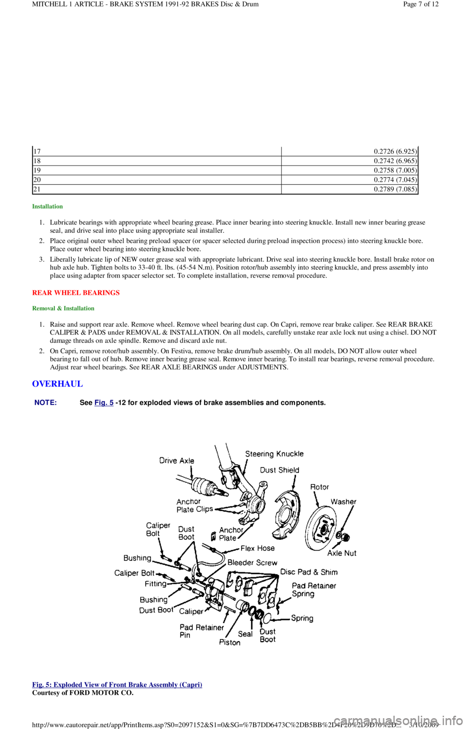
Fig. 5: Exploded View of Front Brake Assembly (Capri)
Courtesy of FORD MOTOR CO.
170.2726 (6.925)
180.2742 (6.965)
190.2758 (7.005)
200.2774 (7.045)
210.2789 (7.085)
NOTE:See Fig. 5
-12 for exploded views of brake assem blies and com ponents.
Page 7 of 12 MITCHELL 1 ARTICLE - BRAKE SYSTEM 1991-92 BRAKES Disc & Drum
3/10/2009 http://www.eautorepair.net/app/PrintItems.asp?S0=2097152&S1=0&SG=%7B7DD6473C%2DB5BB%2D4F20%2D9D70%2D
...
Page 38 of 454
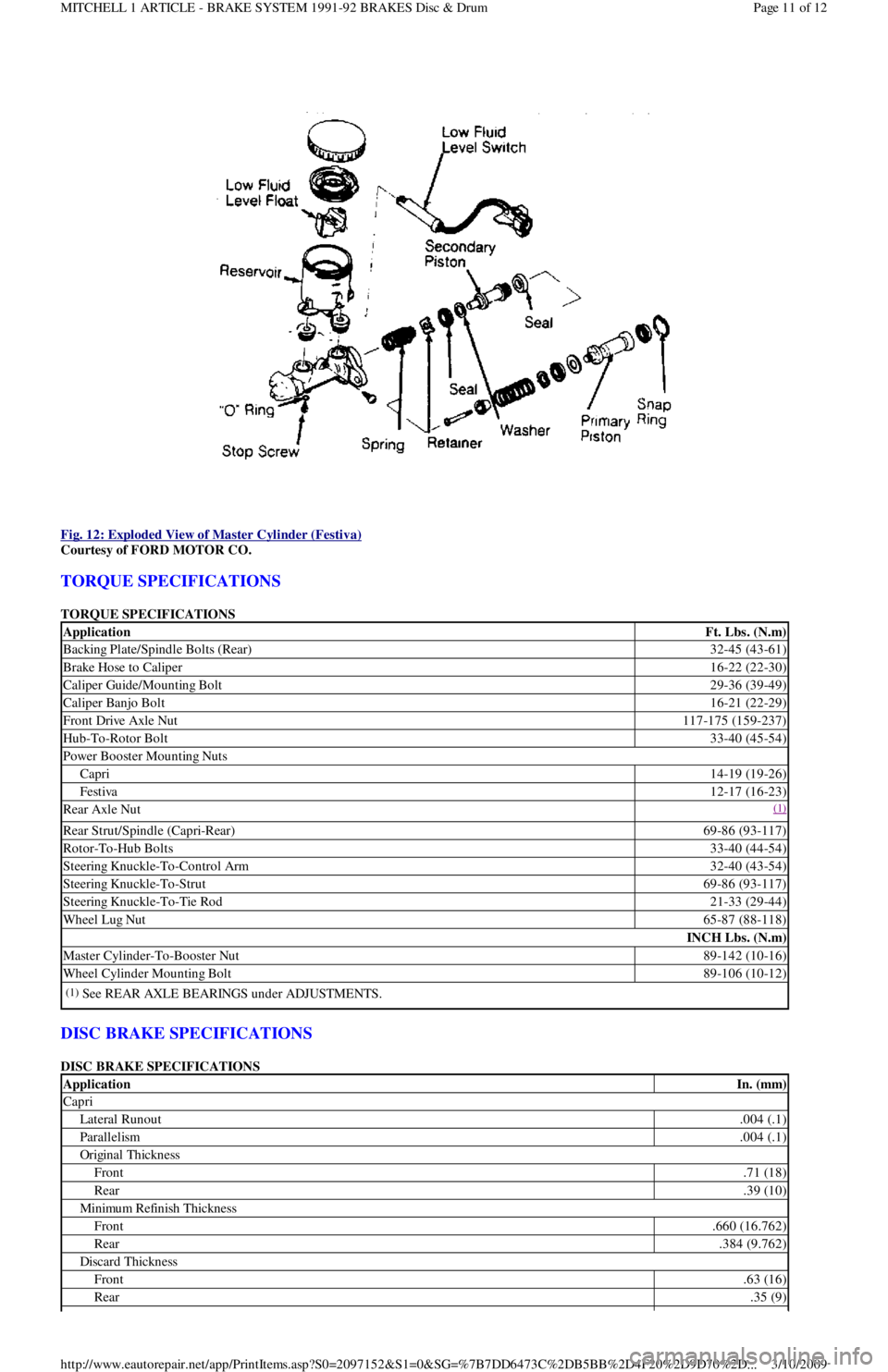
Fig. 12: Exploded View of Master Cylinder (Festiva)
Courtesy of FORD MOTOR CO.
TORQUE SPECIFICATIONS
TORQUE SPECIFICATIONS
DISC BRAKE SPECIFICATIONS
DISC BRAKE SPECIFICATIONS
ApplicationFt. Lbs. (N.m)
Backing Plate/Spindle Bolts (Rear)32-45 (43-61)
Brake Hose to Caliper16-22 (22-30)
Caliper Guide/Mounting Bolt29-36 (39-49)
Caliper Banjo Bolt16-21 (22-29)
Front Drive Axle Nut117-175 (159-237)
Hub-To-Rotor Bolt33-40 (45-54)
Power Booster Mounting Nuts
Capri14-19 (19-26)
Festiva12-17 (16-23)
Rear Axle Nut(1)
Rear Strut/Spindle (Capri-Rear)69-86 (93-117)
Rotor-To-Hub Bolts33-40 (44-54)
Steering Knuckle-To-Control Arm32-40 (43-54)
Steering Knuckle-To-Strut69-86 (93-117)
Steering Knuckle-To-Tie Rod21-33 (29-44)
Wheel Lug Nut65-87 (88-118)
INCH Lbs. (N.m)
Master Cylinder-To-Booster Nut89-142 (10-16)
Wheel Cylinder Mounting Bolt89-106 (10-12)
(1)See REAR AXLE BEARINGS under ADJUSTMENTS.
ApplicationIn. (mm)
Capri
Lateral Runout.004 (.1)
Parallelism.004 (.1)
Original Thickness
Front.71 (18)
Rear.39 (10)
Min imu m Refin ish Th ickn ess
Front.660 (16.762)
Rear.384 (9.762)
Discard Thickness
Front.63 (16)
Rear.35 (9)
Page 11 of 12 MITCHELL 1 ARTICLE - BRAKE SYSTEM 1991-92 BRAKES Disc & Drum
3/10/2009 http://www.eautorepair.net/app/PrintItems.asp?S0=2097152&S1=0&SG=%7B7DD6473C%2DB5BB%2D4F20%2D9D70%2D
...
Page 44 of 454
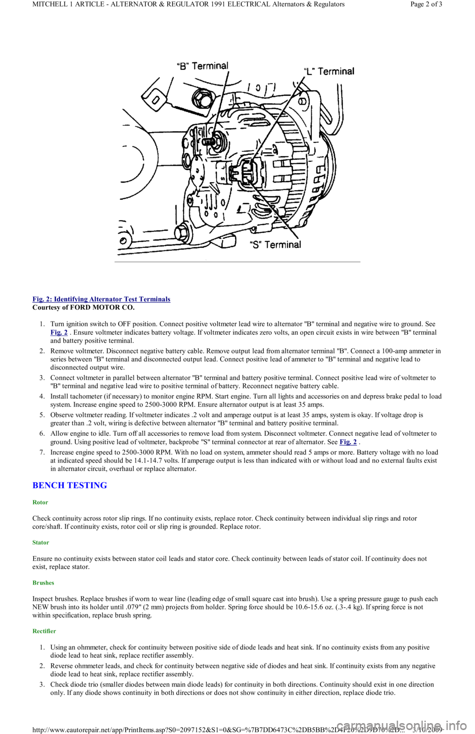
Fig. 2: Identifying Alternator Test Terminals
Courtesy of FORD MOTOR CO.
1. Turn ignition switch to OFF position. Connect positive voltmeter lead wire to alternator "B" terminal and negative wire to ground. See
Fig. 2
. Ensure voltmeter indicates battery voltage. If voltmeter indicates zero volts, an open circuit exists in wire between "B" terminal
and battery positive terminal.
2. Remove voltmeter. Disconnect negative battery cable. Remove output lead from alternator terminal "B". Connect a 100-amp ammeter in
series between "B" terminal and disconnected output lead. Connect positive lead of ammeter to "B" terminal and negative lead to
disconnected output wire.
3. Connect voltmeter in parallel between alternator "B" terminal and battery positive terminal. Connect positive lead wire of voltmeter to
"B" terminal and negative lead wire to positive terminal of battery. Reconnect negative battery cable.
4. Install tachometer (if necessary) to monitor engine RPM. Start engine. Turn all lights and accessories on and depress brake pedal to load
system. Increase engine speed to 2500-3000 RPM. Ensure alternator output is at least 35 amps.
5. Observe voltmeter reading. If voltmeter indicates .2 volt and amperage output is at least 35 amps, system is okay. If voltage drop is
greater than .2 volt, wiring is defective between alternator "B" terminal and battery positive terminal.
6. Allow engine to idle. Turn off all accessories to remove load from system. Disconnect voltmeter. Connect negative lead of voltmeter to
ground. Using positive lead of voltmeter, backprobe "S" terminal connector at rear of alternator. See Fig. 2
.
7. Increase engine speed to 2500-3000 RPM. With no load on system, ammeter should read 5 amps or more. Battery voltage with no load
at indicated speed should be 14.1-14.7 volts. If amperage output is less than indicated with or without load and no external faults exist
in alternator circuit, overhaul or replace alternator.
BENCH TESTING
Rotor
Check continuity across rotor slip rings. If no continuity exists, replace rotor. Check continuity between individual slip rings and rotor
core/shaft. If continuity exists, rotor coil or slip ring is grounded. Replace rotor.
Stator
Ensure no continuity exists between stator coil leads and stator core. Check continuity between leads of stator coil. If continuity does not
exist, replace stator.
Brushes
Inspect brushes. Replace brushes if worn to wear line (leading edge of small square cast into brush). Use a spring pressure gauge to push each
NEW brush into its holder until .079" (2 mm) projects from holder. Spring force should be 10.6-15.6 oz. (.3-.4 kg). If spring force is not
within specification, replace brush spring.
Rectifier
1. Using an ohmmeter, check for continuity between positive side of diode leads and heat sink. If no continuity exists from any positive
diode lead to heat sink, replace rectifier assembly.
2. Reverse ohmmeter leads, and check for continuity between negative side of diodes and heat sink. If continuity exists from any n e ga t ive
diode lead to heat sink, replace rectifier assembly.
3. Check diode trio (smaller diodes between main diode leads) for continuity in both directions. Continuity should exist in one direction
only. If any diode shows continuity in both directions or does not show continuity in either direction, replace diode trio.
Page 2 of 3 MITCHELL 1 ARTICLE - ALTERNATOR & REGULATOR 1991 ELECTRICAL Alternators & Regulators
3/10/2009 http://www.eautorepair.net/app/PrintItems.asp?S0=2097152&S1=0&SG=%7B7DD6473C%2DB5BB%2D4F20%2D9D70%2D
...
Page 220 of 454
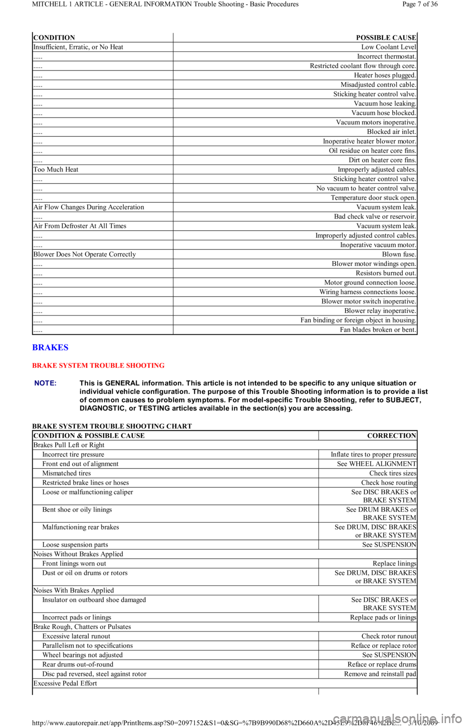
BRAKES
BRAKE SYSTEM TROUBLE SHOOTING
BRAKE SYSTEM TROUBLE SHOOTING CHART
CONDITIONPOSSIBLE CAUSE
Insufficient, Erratic, or No HeatLow Coolant Level
.....Incorrect thermostat.
.....Restricted coolant flow through core.
.....Heater hoses plugged.
.....Misadjusted control cable.
.....Sticking heater control valve.
.....Vacuum hose leaking.
.....Vacuum hose blocked.
.....Vacuum motors inoperative.
.....Blocked air inlet.
.....Inoperative heater blower motor.
.....Oil residue on heater core fins.
.....Dirt on heater core fins.
Too Much HeatImproperly adjusted cables.
.....Sticking heater control valve.
.....No vacuum to heater control valve.
.....Temperature door stuck open.
Air Flow Changes During AccelerationVacuum system leak.
.....Bad check valve or reservoir.
Air From Defroster At All TimesVacuum system leak.
.....Improperly adjusted control cables.
.....Inoperative vacuum motor.
Blower Does Not Operate CorrectlyBlown fuse.
.....Blower motor windings open.
.....Resistors burned out.
.....Motor ground connection loose.
.....Wiring harness connections loose.
.....Blower motor switch inoperative.
.....Blower relay inoperative.
.....Fan binding or foreign object in housing.
.....Fan blades broken or bent.
NOTE:This is GENERAL inform ation. This article is not intended to be specific to any unique situation or
individual vehicle configuration. T he purpose of this T rouble Shooting inform ation is to provide a list
of com m on causes to problem sym ptom s. For m odel-specific T rouble Shooting, refer to SUBJECT ,
DIAGNOST IC, or T EST ING articles available in the section(s) you are accessing.
CONDITION & POSSIBLE CAUSECORRECTION
Brakes Pull Left or Right
Incorrect tire pressureInflate tires to proper pressure
Front end out of alignmentSee WHEEL ALIGNMENT
Mismatched tiresCheck tires sizes
Restricted brake lines or hosesCheck hose routing
Loose or malfunctioning caliperSee DISC BRAKES or
BRAKE SYSTEM
Bent shoe or oily liningsSee DRUM BRAKES or
BRAKE SYSTEM
Malfunctioning rear brakesSee DRUM, DISC BRAKES
or BRAKE SYSTEM
Loose suspension partsSee SUSPENSION
Noises Without Brakes Applied
Front linings worn outReplace linings
Dust or oil on drums or rotorsSee DRUM, DISC BRAKES
or BRAKE SYSTEM
Noises With Brakes Applied
Insulator on outboard shoe damagedSee DISC BRAKES or
BRAKE SYSTEM
Incorrect pads or liningsReplace pads or linings
Brake Rough, Chatters or Pulsates
Excessive lateral runoutCheck rotor runout
Parallelism not to specificationsReface or replace rotor
Wheel bearings not adjustedSee SUSPENSION
Rear drums out-of-roundReface or replace drums
Disc pad reversed, steel against rotorRemove and reinstall pad
Excessive Pedal Effort
Page 7 of 36 MITCHELL 1 ARTICLE - GENERAL INFORMATION Trouble Shooting - Basic Procedures
3/10/2009 http://www.eautorepair.net/app/PrintItems.asp?S0=2097152&S1=0&SG=%7B9B990D68%2D660A%2D45E9%2D8F46%2DE
...
Page 221 of 454
ENGINE MECHANICAL
COOLING SYSTEM TROUBLE SHOOTING
COOLING SYSTEM TROUBLE SHOOTING
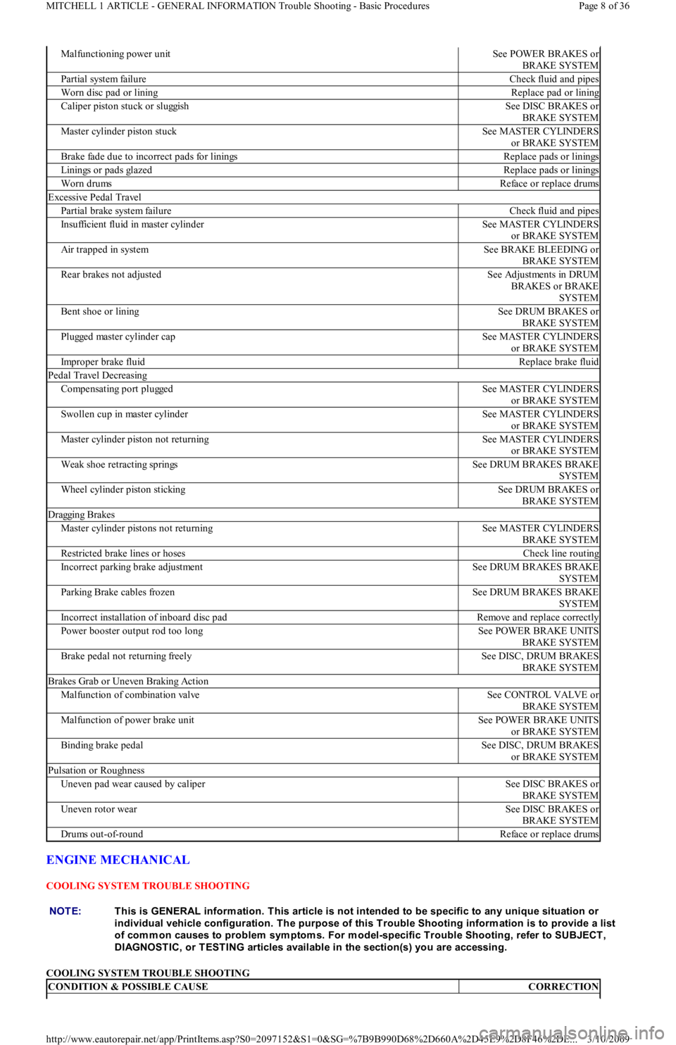
Malfunctioning power unitSee POWER BRAKES or
BRAKE SYSTEM
Partial system failureCheck fluid and pipes
Worn disc pad or liningReplace pad or lining
Caliper piston stuck or sluggishSee DISC BRAKES or
BRAKE SYSTEM
Master cylinder piston stuckSee MASTER CYLINDERS
or BRAKE SYSTEM
Brake fade due to incorrect pads for liningsReplace pads or linings
Linings or pads glazedReplace pads or linings
Worn drumsReface or replace drums
Excessive Pedal Travel
Partial brake system failureCheck fluid and pipes
Insufficient fluid in master cylinderSee MASTER CYLINDERS
or BRAKE SYSTEM
Air trapped in systemSee BRAKE BLEEDING or
BRAKE SYSTEM
Rear brakes not adjustedSee Adjustments in DRUM
BRAKES or BRAKE
SYSTEM
Bent shoe or liningSee DRUM BRAKES or
BRAKE SYSTEM
Plugged master cylinder capSee MASTER CYLINDERS
or BRAKE SYSTEM
Improper brake fluidReplace brake fluid
Pedal Travel Decreasing
Compensating port pluggedSee MASTER CYLINDERS
or BRAKE SYSTEM
Swollen cup in master cylinderSee MASTER CYLINDERS
or BRAKE SYSTEM
Master cylinder piston not returningSee MASTER CYLINDERS
or BRAKE SYSTEM
Weak shoe retracting springsSee DRUM BRAKES BRAKE
SYSTEM
Wheel cylinder piston stickingSee DRUM BRAKES or
BRAKE SYSTEM
Dragging Brakes
Master cylinder pistons not returningSee MASTER CYLINDERS
BRAKE SYSTEM
Restricted brake lines or hosesCheck line routing
Incorrect parking brake adjustmentSee DRUM BRAKES BRAKE
SYSTEM
Parking Brake cables frozenSee DRUM BRAKES BRAKE
SYSTEM
Incorrect installation of inboard disc padRemove and replace correctly
Power booster output rod too longSee POWER BRAKE UNITS
BRAKE SYSTEM
Brake pedal not returning freelySee DISC, DRUM BRAKES
BRAKE SYSTEM
Brakes Grab or Uneven Braking Action
Malfunction of combination valveSee CONTROL VALVE or
BRAKE SYSTEM
Malfunction of power brake unitSee POWER BRAKE UNITS
or BRAKE SYSTEM
Binding brake pedalSee DISC, DRUM BRAKES
or BRAKE SYSTEM
Pulsation or Roughness
Uneven pad wear caused by caliperSee DISC BRAKES or
BRAKE SYSTEM
Uneven rotor wearSee DISC BRAKES or
BRAKE SYSTEM
Drums out-of-roundReface or replace drums
NOTE:This is GENERAL inform ation. This article is not intended to be specific to any unique situation or
individual vehicle configuration. T he purpose of this T rouble Shooting inform ation is to provide a list
of com m on causes to problem sym ptom s. For m odel-specific T rouble Shooting, refer to SUBJECT ,
DIAGNOST IC, or T EST ING articles available in the section(s) you are accessing.
CONDITION & POSSIBLE CAUSECORRECTION
Page 8 of 36 MITCHELL 1 ARTICLE - GENERAL INFORMATION Trouble Shooting - Basic Procedures
3/10/2009 http://www.eautorepair.net/app/PrintItems.asp?S0=2097152&S1=0&SG=%7B9B990D68%2D660A%2D45E9%2D8F46%2DE
...
Page 243 of 454
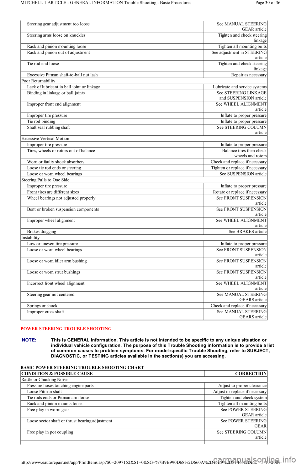
POWER STEERING TROUBLE SHOOTING
BASIC POWER STEERING TROUBLE SHOOTING CHART
Steering gear adjustment too looseSee MANUAL STEERING
GEAR article
Steering arms loose on knucklesTighten and check steering
linkage
Rack and pinion mounting looseTighten all mounting bolts
Rack and pinion out of adjustmentSee adjustment in STEERING
article
Tie rod end looseTighten and check steering
linkage
Excessive Pitman shaft-to-ball nut lashRepair as necessary
Poor Returnability
Lack of lubricant in ball joint or linkageLubricate and service systems
Binding in linkage or ball jointsSee STEERING LINKAGE
and SUSPENSION article
Improper front end alignmentSee WHEEL ALIGNMENT
article
Improper tire pressureInflate to proper pressure
Tie rod bindingInflate to proper pressure
Shaft seal rubbing shaftSee STEERING COLUMN
article
Excessive Vertical Motion
Improper tire pressureInflate to proper pressure
Tires, wheels or rotors out of balanceBalance tires then check
wheels and rotors
Worn or faulty shock absorbersCheck and replace if necessary
Loose tie rod ends or steeringTighten or replace if necessary
Loose or worn wheel bearingsSee SUSPENSION article
Steering Pulls to One Side
Improper tire pressureInflate to proper pressure
Front tires are different sizesRotate or replace if necessary
Wheel bearings not adjusted properlySee FRONT SUSPENSION
article
Bent or broken suspension componentsSee FRONT SUSPENSION
article
Improper wheel alignmentSee WHEEL ALIGNMENT
article
Brakes draggingSee BRAKES article
Instability
Low or uneven tire pressureInflate to proper pressure
Loose or worn wheel bearingsSee FRONT SUSPENSION
article
Loose or worn idler arm bushingSee FRONT SUSPENSION
article
Loose or worn strut bushingsSee FRONT SUSPENSION
article
Incorrect front wheel alignmentSee WHEEL ALIGNMENT
article
Steering gear not centeredSee MANUAL STEERING
GEARS article
Springs or shockCheck and replace if necessary
Improper cross shaftSee MANUAL STEERING
GEARS article
NOTE:This is GENERAL inform ation. This article is not intended to be specific to any unique situation or
individual vehicle configuration. T he purpose of this T rouble Shooting inform ation is to provide a list
of com m on causes to problem sym ptom s. For m odel-specific T rouble Shooting, refer to SUBJECT ,
DIAGNOST IC, or T EST ING articles available in the section(s) you are accessing.
CONDITION & POSSIBLE CAUSECORRECTION
Rattle or Chucking Noise
Pressure hoses touching engine partsAdjust to proper clearance
Loose Pitman shaftAdjust or replace if necessary
Tie rods ends or Pitman arm looseTighten and check system
Rack and pinion mounts looseTighten all mounting bolts
Free play in worm gearSee POWER STEERING
GEAR article
Loose sector shaft or thrust bearing adjustmentSee POWER STEERING
GEAR
Free play in pot couplingSee STEERING COLUMN
article
Page 30 of 36 MITCHELL 1 ARTICLE - GENERAL INFORMATION Trouble Shooting - Basic Procedures
3/10/2009 http://www.eautorepair.net/app/PrintItems.asp?S0=2097152&S1=0&SG=%7B9B990D68%2D660A%2D45E9%2D8F46%2DE
...
Page 392 of 454
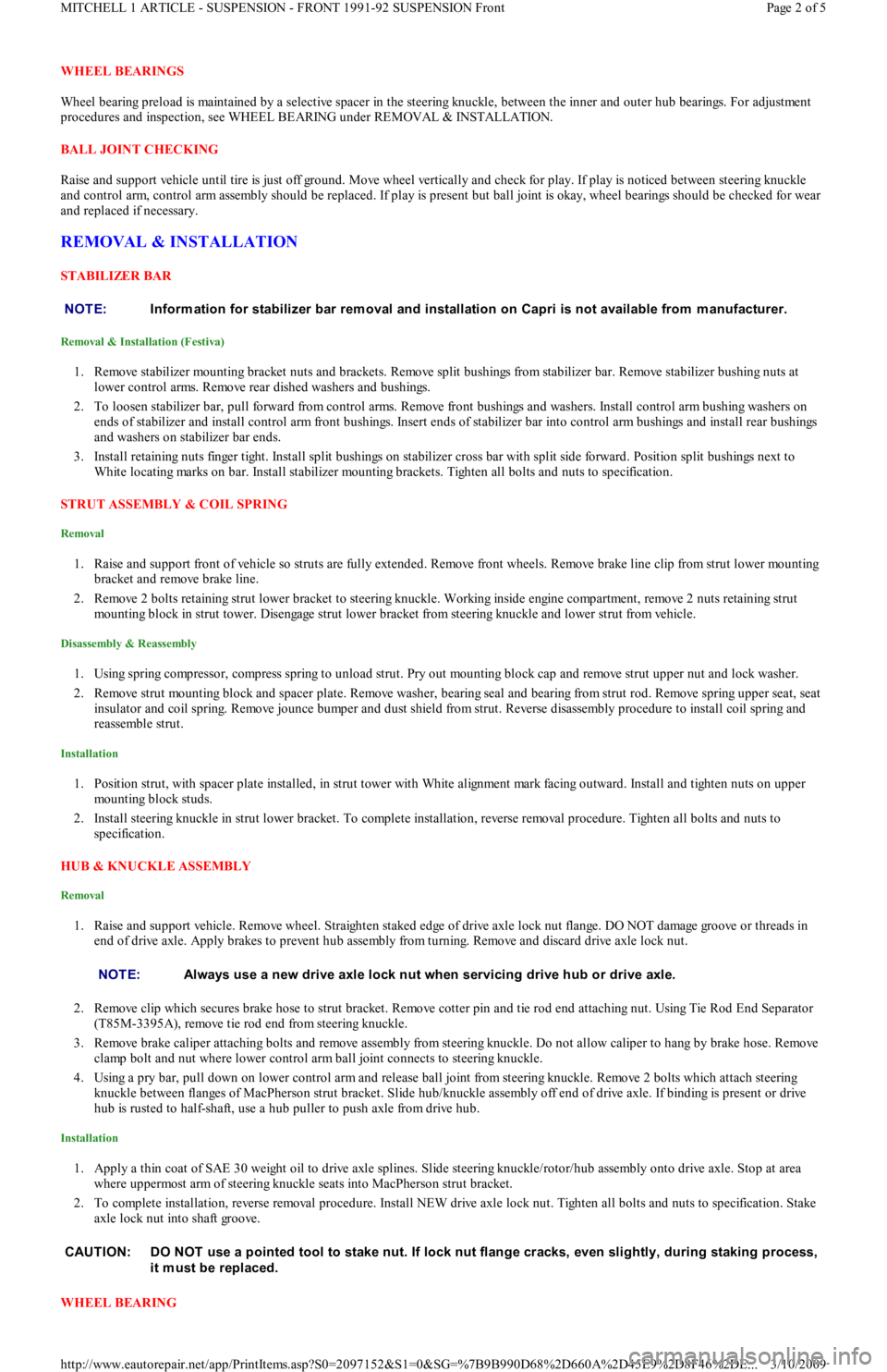
WHEEL BEARINGS
Wheel bearing preload is maintained by a selective spacer in the steering knuckle, between the inner and outer hub bearings. For adjustment
procedures and inspection, see WHEEL BEARING under REMOVAL & INSTALLATION.
BALL JOINT CHECKING
Raise and support vehicle until tire is just off ground. Move wheel vertically and check for play. If play is noticed between steering knuckle
and control arm, control arm assembly should be replaced. If play is present but ball joint is okay, wheel bearings should be checked for wear
and replaced if necessary.
REMOVAL & INSTALLATION
STABILIZER BAR
Removal & Installation (Festiva)
1. Remove stabilizer mounting bracket nuts and brackets. Remove split bushings from stabilizer bar. Remove stabilizer bushing nuts at
lower control arms. Remove rear dished washers and bushings.
2. To loosen stabilizer bar, pull forward from control arms. Remove front bushings and washers. Install control arm bushing washers on
ends of stabilizer and install control arm front bushings. Insert ends of stabilizer bar into control arm bushings and install rear bushings
and washers on stabilizer bar ends.
3. Install retaining nuts finger tight. Install split bushings on stabilizer cross bar with split side forward. Position split bushings next to
White locating marks on bar. Install stabilizer mounting brackets. Tighten all bolts and nuts to specification.
STRUT ASSEMBLY & COIL SPRING
Removal
1. Raise and support front of vehicle so struts are fully extended. Remove front wheels. Remove brake line clip from strut lower mounting
bracket and remove brake line.
2. Remove 2 bolts retaining strut lower bracket to steering knuckle. Working inside engine compartment, remove 2 nuts retaining strut
mounting block in strut tower. Disengage strut lower bracket from steering knuckle and lower strut from vehicle.
Disassembly & Reassembly
1. Using spring compressor, compress spring to unload strut. Pry out mounting block cap and remove strut upper nut and lock washer.
2. Remove strut mounting block and spacer plate. Remove washer, bearing seal and bearing from strut rod. Remove spring upper seat, seat
insulator and coil spring. Remove jounce bumper and dust shield from strut. Reverse disassembly procedure to install coil spring a n d
reassemble strut.
Installation
1. Position strut, with spacer plate installed, in strut tower with White alignment mark facing outward. Install and tighten nuts on upper
mounting block studs.
2. Install steering knuckle in strut lower bracket. To complete installation, reverse removal procedure. Tighten all bolts and nuts to
specification.
HUB & KNUCKLE ASSEMBLY
Removal
1. Raise and support vehicle. Remove wheel. Straighten staked edge of drive axle lock nut flange. DO NOT damage groove or threads in
end of drive axle. Apply brakes to prevent hub assembly from turning. Remove and discard drive axle lock nut.
2. Remove clip which secures brake hose to strut bracket. Remove cotter pin and tie rod end attaching nut. Using Tie Rod End Separator
(T85M-3395A), remove tie rod end from steering knuckle.
3. Remove brake caliper attaching bolts and remove assembly from steering knuckle. Do not allow caliper to hang by brake hose. Remove
clamp bolt and nut where lower control arm ball joint connects to steering knuckle.
4. Using a pry bar, pull down on lower control arm and release ball joint from steering knuckle. Remove 2 bolts which attach steering
knuckle between flanges of MacPherson strut bracket. Slide hub/knuckle assembly off end of drive axle. If binding is present or drive
hub is rusted to half-shaft, use a hub puller to push axle from drive hub.
Installation
1. Apply a thin coat of SAE 30 weight oil to drive axle splines. Slide steering knuckle/rotor/hub assembly onto drive axle. Stop at area
where uppermost arm of steering knuckle seats into MacPherson strut bracket.
2. To complete installation, reverse removal procedure. Install NEW drive axle lock nut. Tighten all bolts and nuts to specification. Stake
axle lock nut into shaft groove.
WHEEL BEARING NOTE:Inform ation for stabilizer bar rem oval and installation on Capri is not available from m anufacturer.
NOTE:Always use a new drive axle lock nut when servicing drive hub or drive axle.
CAUT ION: DO NOT use a pointed tool to stake nut. If lock nut flange cracks, even slightly, during staking process,
it m ust be replaced.
Page 2 of 5 MITCHELL 1 ARTICLE - SUSPENSION - FRONT 1991-92 SUSPENSION Front
3/10/2009 http://www.eautorepair.net/app/PrintItems.asp?S0=2097152&S1=0&SG=%7B9B990D68%2D660A%2D45E9%2D8F46%2DE
...