parking brake FORD FESTIVA 1991 Service Manual
[x] Cancel search | Manufacturer: FORD, Model Year: 1991, Model line: FESTIVA, Model: FORD FESTIVA 1991Pages: 454, PDF Size: 9.53 MB
Page 28 of 454
Back To Article
BRAKE SYST EM
1991-92 BRAKES Disc & Drum
DESCRIPTION & OPERATION
On Capri, vehicle braking is provided by front and rear disc brakes. Front and rear brakes are a full-floating, single piston design. The rear
caliper houses a self-adjusting parking brake.
On Festiva, vehicle braking is provided by front disc brakes and rear drum brakes. Rear brakes are a standard non-servo, self-en e r giz in g d e sign .
Front brakes are a full-floating, single piston design with caliper attached to steering knuckle.
BLEEDING BRAKE SYSTEM
BLEEDING PROCEDURES
Manual Bleeding
1. Exhaust vacuum from power brake unit by depressing brake pedal several times. Fill master cylinder with clean brake fluid. Install clear
vinyl bleeder hose onto first bleeder valve to be serviced. See BRAKE LINE BLEEDING SEQUENCE table. Place other end of hose in
clean transparent container.
2. Partially fill container with clean brake fluid. Open the bleeder valve 3/4 turn. Slowly depress brake pedal through its full travel. Close
bleeder valve and release pedal. Pump pedal several times to push air toward wheel cylinders. Repeat procedure until flow of brake
fluid is clear and shows no signs of air bubbles. Proceed to next bleeder valve in sequence and repeat procedure.
BRAKE LINE BLEEDING SEQUENCE
Pressure Bleeding
1. Exhaust vacuum from power brake unit by depressing brake pedal several times. Fill master cylinder with clean brake fluid. With
pressure bleeder at least 1/2 full, connect pressure bleeder to master cylinder using appropriate adaptor.
2. Install clear vinyl bleeder hose onto first bleeder valve to be serviced. See BRAKE LINE BLEEDING SEQUENCE table. Place other
end of hose in clean transparent container. Partially fill container with clean brake fluid. Open bleeder valve 1-2 turns. Allow fluid to
run until flow of fluid is clear and shows no signs of air bubbles. Proceed to next bleeder valve in sequence and repeat procedure.
Remove pressure bleeder and fill master cylinder with clean brake fluid.
ADJUSTMENTS
BRAKE PEDAL HEIGHT (FESTIVA)
1. Block wheels to prevent vehicle from rolling. Start engine and place transmission in Neutral. Fully release parking brake. Move carpet
and insulation away from firewall and brake pedal. Measure distance horizontally between upper center of brake pedal pad and firewall.
Distance should be 8.03-8.23" (204-209 mm).
2. If pedal height is incorrect, inspect pedal assembly for missing, worn or damaged bushings or for loose attaching bolts. Ensure firewall is
not distorted and pedal is not bent. If pedal height is still not within specifications, check brake pedal, booster or master cylinder for
correct and/or correctly installed parts
BRAKE PEDAL FREE PLAY (FESTIVA)
Pump brake pedal several to bleed vacuum from power brake booster. Gently depress brake pedal by hand and measure and measure play
before resistance is felt. Free play should be .16-.28" (4-7 mm). If free play is not within specifications, adjust brake pedal push rod.
BRAKE PEDAL FLOOR CLEARANCE
Capri
1. Move carpet and insulation away from floor board and brake pedal. With engine running and using Brake Pedal Effort Gauge (021-
00001), apply 132 lbs. (59.9 kg) of force to brake pedal. Measure distance from upper surface of brake pedal pad to floor board. If
distance is less than 3.27" (83 mm), inspect pedal assembly for missing, worn or damaged bushings or for loose attaching bolts.
2. Verify that floor board is not distorted and pedal is not bent. If pedal height is still not within specifications, check brake pedal, booster
or master cylinder for correct and/or correctly installed parts. Check for air in hydraulic system.
Festiva
Move carpet and insulation away from floor board and brake pedal. Using Brake Pedal Effort Gauge (021-00001) or equivalent, apply 132
lbs. (59.9 kg) of force to brake pedal. Measure distance from upper surface of brake pedal pad to floor board. If distance is less than 2.68" (68
mm), check for air in hydraulic system, faulty automatic adjusters or excessive shoe clearance.
POWER BRAKE UNIT PUSH ROD
Capri
ApplicationSequence
CapriRR, LF, LR & RF
FestivaRR, LR, RF & LF
NOTE:Check fluid level in m aster cylinder frequently during the bleeding sequence.
Page 1 of 12 MITCHELL 1 ARTICLE - BRAKE SYSTEM 1991-92 BRAKES Disc & Drum
3/10/2009 http://www.eautorepair.net/app/PrintItems.asp?S0=2097152&S1=0&SG=%7B7DD6473C%2DB5BB%2D4F20%2D9D70%2D
...
Page 29 of 454
Power brake push rod length is not adjustable.
Festiva
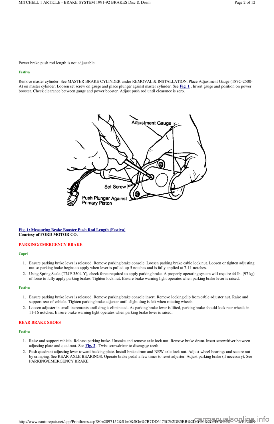
Remove master cylinder. See MASTER BRAKE CYLINDER under REMOVAL & INSTALLATION. Place Adjustment Gauge (T87C-2500-
A) on master cylinder. Loosen set screw on gauge and place plunger against master cylinder. See Fig. 1
. Invert gauge and position on power
booster. Check clearance between gauge and power booster. Adjust push rod until clearance is zero.
Fig. 1: Measuring Brake Booster Push Rod Length (Festiva)
Courtesy of FORD MOTOR CO.
PARKING/EMERGENCY BRAKE
Capri
1. Ensure parking brake lever is released. Remove parking brake console. Loosen parking brake cable lock nut. Loosen or tighten adjusting
nut so parking brake begins to apply when lever is pulled up 5 notches and is fully applied at 7-11 notches.
2. Using Spring Scale (T74P-3504-Y), check force required to apply parking brake. A properly operating system will require 44 lb. (97 kg)
of force to fully apply parking brakes. Tighten lock nut. Ensure brake warning light operates when parking brake lever is raised.
Festiva
1. Ensure parking brake lever is released. Remove parking brake console insert. Remove locking clip from cable adjuster nut. Raise and
support rear of vehicle. Tighten parking brake adjuster until slight drag is felt when rotating wheels.
2. Loosen adjuster in small increments until drag is eliminated. As parking brake lever is lifted, parking brake should lock rear wheels in
11-16 notches. Ensure brake warning light operates when parking brake lever is raised.
REAR BRAKE SHOES
Festiva
1. Raise and support vehicle. Release parking brake. Unstake and remove axle lock nut. Remove brake drum. Insert screwdriver between
adjusting plate and quadrant. See Fig. 2
. Twist screwdriver to disengage teeth.
2. Push quadrant adjusting lever toward backing plate. Install brake drum and NEW axle lock nut. Adjust wheel bearings and secure nut
by crimping. See REAR AXLE BEARINGS. Operate brake pedal a few times to reset adjuster. Adjust parking brake (if necessary). See
PARKING/EMERGENCY BRAKE.
Page 2 of 12 MITCHELL 1 ARTICLE - BRAKE SYSTEM 1991-92 BRAKES Disc & Drum
3/10/2009 http://www.eautorepair.net/app/PrintItems.asp?S0=2097152&S1=0&SG=%7B7DD6473C%2DB5BB%2D4F20%2D9D70%2D
...
Page 30 of 454
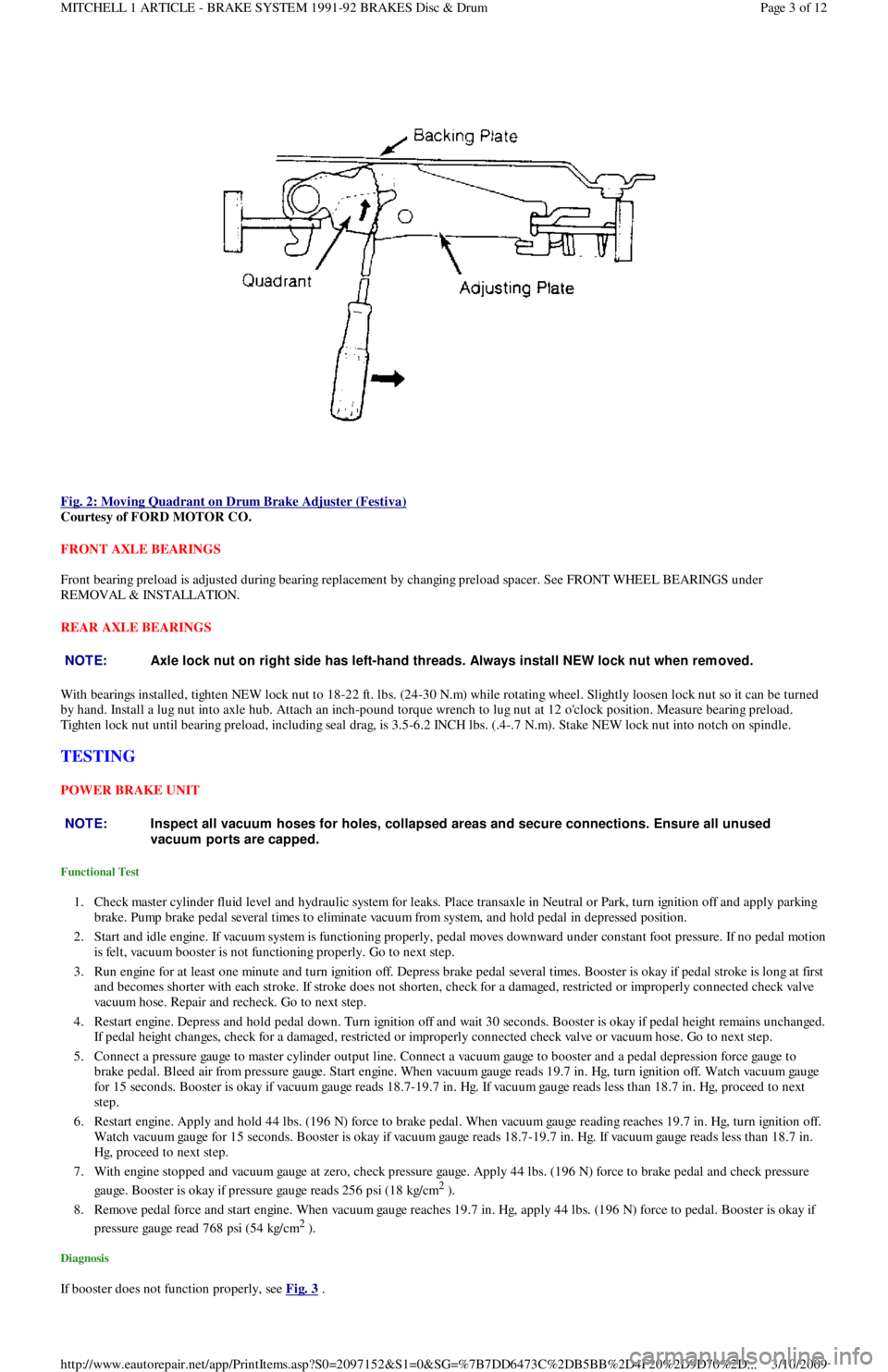
Fig. 2: Moving Quadrant on Drum Brake Adjuster (Festiva)
Courtesy of FORD MOTOR CO.
FRONT AXLE BEARINGS
Front bearing preload is adjusted during bearing replacement by changing preload spacer. See FRONT WHEEL BEARINGS under
REMOVAL & INSTALLATION.
REAR AXLE BEARINGS
With bearings installed, tighten NEW lock nut to 18-22 ft. lbs. (24-30 N.m) while rotating wheel. Slightly loosen lock nut so it can be turned
by hand. Install a lug nut into axle hub. Attach an inch-pound torque wrench to lug nut at 12 o'clock position. Measure bearing preload.
Tighten lock nut until bearing preload, including seal drag, is 3.5-6.2 INCH lbs. (.4-.7 N.m). Stake NEW lock nut into notch on spindle.
TESTING
POWER BRAKE UNIT
Functional Test
1. Check master cylinder fluid level and hydraulic system for leaks. Place transaxle in Neutral or Park, turn ignition off and apply parking
brake. Pump brake pedal several times to eliminate vacuum from system, and hold pedal in depressed position.
2. Start and idle engine. If vacuum system is functioning properly, pedal moves downward under constant foot pressure. If no pedal motion
is felt, vacuum booster is not functioning properly. Go to next step.
3. Run engine for at least one minute and turn ignition off. Depress brake pedal several times. Booster is okay if pedal stroke is long at first
and becomes shorter with each stroke. If stroke does not shorten, check for a damaged, restricted or improperly connected check va l ve
vacuum hose. Repair and recheck. Go to next step.
4. Restart engine. Depress and hold pedal down. Turn ignition off and wait 30 seconds. Booster is okay if pedal height remains unchanged.
If pedal height changes, check for a damaged, restricted or improperly connected check valve or vacuum hose. Go to next step.
5. Connect a pressure gauge to master cylinder output line. Connect a vacuum gauge to booster and a pedal depression force gauge to
brake pedal. Bleed air from pressure gauge. Start engine. When vacuum gauge reads 19.7 in. Hg, turn ignition off. Watch vacuum ga u ge
for 15 seconds. Booster is okay if vacuum gauge reads 18.7-19.7 in. Hg. If vacuum gauge reads less than 18.7 in. Hg, proceed to next
step.
6. Restart engine. Apply and hold 44 lbs. (196 N) force to brake pedal. When vacuum gauge reading reaches 19.7 in. Hg, turn ignition off.
Watch vacuum gauge for 15 seconds. Booster is okay if vacuum gauge reads 18.7-19.7 in. Hg. If vacuum gauge reads less than 18.7 in.
Hg, proceed to next step.
7. With engine stopped and vacuum gauge at zero, check pressure gauge. Apply 44 lbs. (196 N) force to brake pedal and check pressure
gauge. Booster is okay if pressure gauge reads 256 psi (18 kg/cm
2 ).
8. Remove pedal force and start engine. When vacuum gauge reaches 19.7 in. Hg, apply 44 lbs. (196 N) force to pedal. Booster is okay if
pressure gauge read 768 psi (54 kg/cm
2 ).
Diagnosis
If booster does not function properly, see Fig. 3 .
NOTE:Axle lock nut on right side has left-hand threads. Always install NEW lock nut when rem oved.
NOTE:Inspect all vacuum hoses for holes, collapsed areas and secure connections. Ensure all unused
vacuum ports are capped.
Page 3 of 12 MITCHELL 1 ARTICLE - BRAKE SYSTEM 1991-92 BRAKES Disc & Drum
3/10/2009 http://www.eautorepair.net/app/PrintItems.asp?S0=2097152&S1=0&SG=%7B7DD6473C%2DB5BB%2D4F20%2D9D70%2D
...
Page 32 of 454
lock nut. Discard axle lock nut. Separate tie rod end from knuckle.
2. Disconnect brake hose from strut (if necessary). Remove brake caliper assembly from knuckle and wire out of way. Remove nuts and
bolts holding ball joint and strut to knuckle assembly.
3. Remove knuckle assembly from ball joint and drive shaft. If binding occurs, use a dual-jawed puller to force knuckle/hub/rotor assembly
off drive axle shaft.
4. Using a puller, separate knuckle from wheel hub. Retain original outer bearing preload spacer to maintain bearing preload setting. If
replacing bearing, change spacer to maintain proper bearing preload (if necessary). See FRONT WHEEL BEARINGS under REMOVAL
& INSTALLATION. Scribe match marks between hub and rotor assembly. Remove rotor-to-hub bolts. Separate hub from rotor.
Installation
Align marks and install rotor on hub. Press knuckle and preload spacer into wheel hub assembly. To complete installation, reverse removal
procedure. Tighten axle shaft lock nut to 117-175 ft. lbs. (159-237 N.m).
REAR BRAKE CALIPER & PADS
Removal (Capri)
1. Raise and support vehicle. Remove tire and wheel assembly. Using needle-nose pliers, remove parking brake return spring. Loosen
parking brake cable housing adjusting nut. Remove cable housing from bracket on lower control arm. Loosen parking brake cable
bracket-to-caliper attaching bolt. Remove parking brake cable from caliper.
2. Remove lower caliper retaining bolt. Pivot caliper upward on upper caliper guide pin. Remove brake pad retaining spring, pads and
shims. If replacing rear brake pads only, reverse removal procedure to install. If removing caliper, proceed to next step.
3. Remove attaching clip from brake flex hose. Remove flex hose banjo bolt from caliper and discard copper washers. Remove lower
caliper retaining bolt. Using a cold chisel, remove upper caliper guide pin dust cap. Using an Allen wrench, remove upper caliper guide
pin. Lift caliper off rotor.
Installation
1. To install, fit brake pads and shims into caliper anchor plate. Remove upper guide pin and lower guide pin bushing from caliper.
Remove guide pin and guide pin bushing dust boots. Lubricate upper guide pin and lower guide pin bushing with Disc Brake Caliper
Slide Grease (D7AZ-19590-A).
2. To complete installation, reverse removal procedure. To fit caliper over new brake pads, it may be necessary to rotate caliper piston into
caliper bore. Use NEW copper washers on flex hose. Bleed brakes, and then pump brake pedal several times to seat pads.
REAR BRAKE ROTOR
Removal & Installation (Capri)
See REAR WHEEL BEARINGS under REMOVAL & INSTALLATION.
REAR BRAKE SHOES
Removal & Installation (Festiva)
Remove brake drum. Remove hold-down springs. Remove return springs. Remove self adjuster. See Fig. 8 . To install, reverse removal
procedure. Apply brake grease to all shoe contact points. See REAR BRAKE SHOES under ADJUSTMENTS.
REAR WHEEL CYLINDER
Removal & Installation (Festiva)
Remove rear brake shoes. Disconnect brake line from wheel cylinder. Remove wheel cylinder. To install, reverse removal procedure. Bleed
brake system.
MASTER BRAKE CYLINDER
Removal
Disconnect low fluid level sensor wiring (if equipped). Drain some brake fluid from reservoir. Disconnect brake lines from master cylinder.
Cap lines and master cylinder ports. Remove attaching nuts and master cylinder.
Installation
To install, reverse removal procedure. Fill master cylinder to proper level and bleed hydraulic system (if necessary).
POWER BRAKE UNIT
Removal & Installation
Remove master cylinder. Disconnect vacuum line. Remove clevis pin at brake pedal. Remove power brake unit. To install, reverse removal
procedure.
FRONT WHEEL BEARINGS NOTE:Hub and rotor are a m atched and balanced assem bly. Before rem oving rotor, locate paint or etch
m ark indicating proper hub-to-rotor alignm ent. If m arks are not present, m ark hub and rotor for
assem bly alignm ent. Failure to properly align hub and rotor can result in an im balance condition.
Page 5 of 12 MITCHELL 1 ARTICLE - BRAKE SYSTEM 1991-92 BRAKES Disc & Drum
3/10/2009 http://www.eautorepair.net/app/PrintItems.asp?S0=2097152&S1=0&SG=%7B7DD6473C%2DB5BB%2D4F20%2D9D70%2D
...
Page 47 of 454
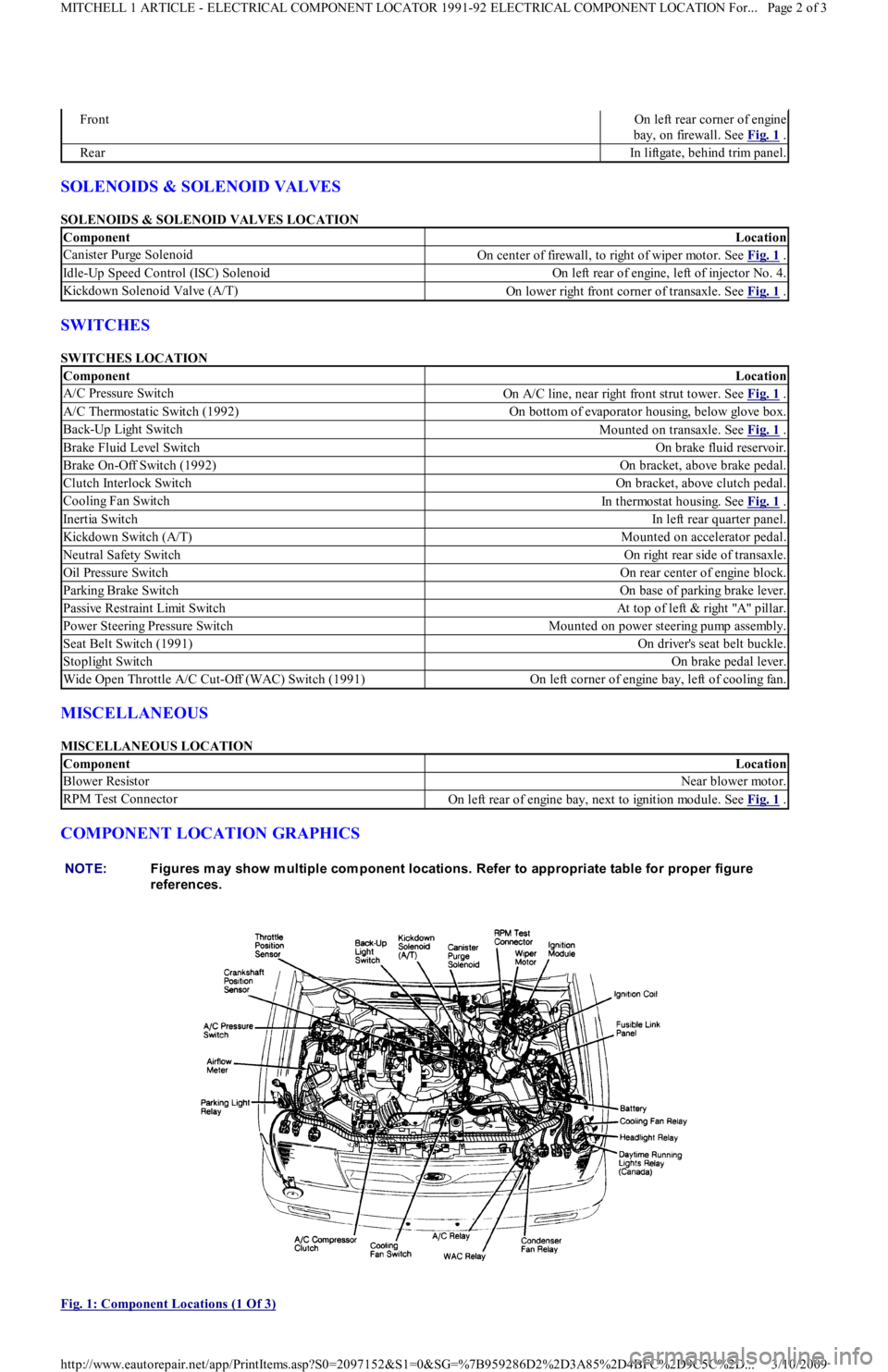
SOLENOIDS & SOLENOID VALVES
SOLENOIDS & SOLENOID VALVES LOCATION
SWITCHES
SWITCHES LOCATION
MISCELLANEOUS
MISCELLANEOUS LOCATION
COMPONENT LOCATION GRAPHICS
Fig. 1: Component Locations (1 Of 3)
FrontOn left rear corner of engine
bay, on firewall. See Fig. 1
.
RearIn liftgate, behind trim panel.
ComponentLocation
Canister Purge SolenoidOn center of firewall, to right of wiper motor. See Fig. 1 .
Idle-Up Speed Control (ISC) SolenoidOn left rear of engine, left of injector No. 4.
Kickdown Solenoid Valve (A/T)On lower right front corner of transaxle. See Fig. 1 .
ComponentLocation
A/C Pressure SwitchOn A/C line, near right front strut tower. See Fig. 1 .
A/C Thermostatic Switch (1992)On bottom of evaporator housing, below glove box.
Back-Up Light SwitchMounted on transaxle. See Fig. 1 .
Brake Fluid Level SwitchOn brake fluid reservoir.
Brake On-Off Switch (1992)On bracket, above brake pedal.
Clutch Interlock SwitchOn bracket, above clutch pedal.
Cooling Fan SwitchIn thermostat housing. See Fig. 1 .
Inertia SwitchIn left rear quarter panel.
Kickdown Switch (A/T)Mounted on accelerator pedal.
Neutral Safety SwitchOn right rear side of transaxle.
Oil Pressure SwitchOn rear center of engine block.
Parking Brake SwitchOn base of parking brake lever.
Passive Restraint Limit SwitchAt top of left & right "A" pillar.
Power Steering Pressure SwitchMounted on power steering pump assembly.
Seat Belt Switch (1991)On driver's seat belt buckle.
Stoplight SwitchOn brake pedal lever.
Wide Open Throttle A/C Cut-Off (WAC) Switch (1991)On left corner of engine bay, left of cooling fan.
ComponentLocation
Blower ResistorNear blower motor.
RPM Test ConnectorOn left rear of engine bay, next to ignition module. See Fig. 1 .
NOTE:Figures m ay show m ultiple com ponent locations. Refer to appropriate table for proper figure
references.
Page 2 of 3 MITCHELL 1 ARTICLE - ELECTRICAL COMPONENT LOCATOR 1991-92 ELECTRICAL COMPONENT LOCATION For...
3/10/2009 http://www.eautorepair.net/app/PrintItems.asp?S0=2097152&S1=0&SG=%7B959286D2%2D3A85%2D4BFC%2D9C5C%2D
...
Page 50 of 454
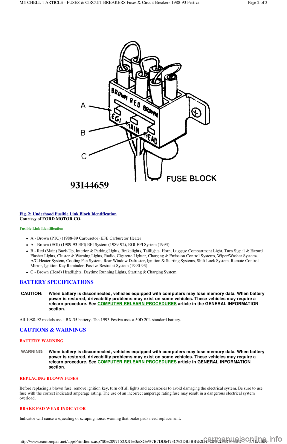
Fig. 2: Underhood Fusible Link Block Identification
Courtesy of FORD MOTOR CO.
Fusible Link Identification
A - Brown (PTC) (1988-89 Carburetor) EFE Carburetor Heater
A - Brown (EGI) (1989-93 EFI) EFI System (1989-92), EGI-EFI System (1993)
B - Red (Main) Back-Up, Interior & Parking Lights, Brakelights, Taillights, Horn, Luggage Compartment Light, Turn Signal & Hazard
F l a sh e r Ligh t s, C l u st e r & Wa r n in g Ligh t s, R a d io , C iga r e t t e Ligh t e r , C h a r gin g & E missio n C o n t r o l S yst e ms, Wip e r / Wa sh e r S yst e ms,
A/C-Heater System, Cooling Fan System, Rear Window Defroster, Ignition & Starting Systems, Shift Lock System, Remote Control
Mirror, Ignition Key Reminder, Passive Restraint System (1990-93)
C - Brown (Head) Headlights, Daytime Running Lights, Starting & Charging System
BATTERY SPECIFICATIONS
All 1988-92 models use a BX-35 battery. The 1993 Festiva uses a 50D 20L standard battery.
CAUTIONS & WARNINGS
BATTERY WARNING
REPLACING BLOWN FUSES
Before replacing a blown fuse, remove ignition key, turn off all lights and accessories to avoid damaging the electrical system. Be sure to use
fuse with the correct indicated amperage rating. The use of an incorrect amperage rating fuse may result in a dangerous electrical system
overload.
BRAKE PAD WEAR INDICATOR
Indicator will cause a squealing or scraping noise, warning that brake pads need replacement.
CAUT ION: When battery is disconnected, vehicles equipped with com puters m ay lose m em ory data. When battery
power is restored, driveability problem s m ay exist on som e vehicles. T hese vehicles m ay require a
relearn procedure. See COMPUTER RELEARN PROCEDURES
article in the GENERAL INFORMAT ION
section.
WARNING:When battery is disconnected, vehicles equipped with com puters m ay lose m em ory data. When battery
power is restored, driveability problem s m ay exist on som e vehicles. T hese vehicles m ay require a
relearn procedure. See COMPUTER RELEARN PROCEDURES
article in GENERAL INFORMAT ION
section.
Page 2 of 3 MITCHELL 1 ARTICLE - FUSES & CIRCUIT BREAKERS Fuses & Circuit Breakers 1988-93 Festiva
3/10/2009 http://www.eautorepair.net/app/PrintItems.asp?S0=2097152&S1=0&SG=%7B7DD6473C%2DB5BB%2D4F20%2D9D70%2D
...
Page 67 of 454
Height SensorElectronic Suspension
HornsSteering Column Switches
Horn RelaySteering Column Switches
Idle Air Control (IAC) Motor/ValveEngine Performance
Ignition Coil(s)Engine Performance
Ignition Key Lock CylinderAnti-Theft System
Ignition ModuleEngine Performance
Ignition SwitchPower Distribution; Engine Performance; Generators &
Regulators; Starters
Illuminated Entry ModuleIllumination/Interior Lights
Illumination LightsIllumination/Interior Lights
Impact SensorAir Bag Restraint System
Inertia Fuel Shutoff SwitchEngine Performance
In h ib it Rel ayStarters
Instrument ClusterAnalog Instrument Panels
Intake Air Temperature (IAT) SensorEngine Performance
Interior LightsIllumination/Interior Lights
In t erl o ck Swit chStarters
Junction BlockPower Distribution
Keyless Entry ReceiverRemote Keyless Entry
Key Reminder SwitchStarters
Knock SensorEngine Performance
Lamp Control ModuleExterior Lights
License Plate LampExterior Lights
Lighting Control ModuleLighting Control Modules; Anti-Theft System; Daytime Running
Lights; Headlight Systems
Lower RelayPower Convertible Top
Malfunction Indicator Light (MIL)Engine Performance; Instrument Panels
Manifold Absolute Pressure (MAP) SensorEngine Performance
Mass Airflow (MAF) SensorEngine Performance
Mega FuseGenerators & Regulators
Memory Seat/Mirror ModuleMemory Systems
M ir r o r De fo gge rRear Window Defogger
Moon Roof MotorPower Moon Roof
Moon Roof RelayPower Moon Roof
Multi-Function Control ModuleWarning Systems
Neutral Safety SwitchStarters
Oil Level SwitchEngine Performance
Oil Pressure Switch/Sending UnitAnalog Instrument Panels; Engine Performance
Overhead ConsoleOverhead Console
Oxygen Sensor(s) (O2S)Engine Performance
Parking Brake SwitchAnalog Instrument Panels
Park LightsExterior Lights
Park/Neutral Position SwitchStarters; Engine Performance; Anti-Theft System; Body Control
Module
Perimeter Lighting Control RelayExterior Lights
Power AmplifierPower Antennas
Power Antenna ModulePower Antennas
Power Antenna MotorPower Antennas
Power Distribution CenterPower Distribution; Generators & Regulators; Starters
Power Door Lock MotorsPower Door Locks
Power Mirror MotorsPower Mirrors; Memory Systems
Power Sliding Door ControllerPower Sliding Side Door
Power Seat MotorsPower Seats; Memory Systems
Power Steering Pressure SwitchEngine Performance
Power Top MotorPower Convertible Top
Power Top Relay(s)Power Convertible Top
Powertrain Control ModuleEngine Performance; Analog Instrument Panels; Cruise Control
Systems; Data Link Connectors; Generators & Regulators; Starters
Power Window MotorsPower Windows
Power Window Relay(s)Power Windows
Radiator Fan Motor(s)Electric Cooling Fans
Radiator Fan Relay(s)Engine Performance; Electric Cooling Fans;
Rainsense ModuleWiper/Washer Systems
Raise RelayPower Convertible Top
Remote Anti-Theft Personality (RAP) ModuleAnti-Theft System; Starters; Warning Systems
Seat Belt PretensionersAir Bag Restraint System
Seat Belt Retractor SolenoidPassive Restraints
Seat Belt SwitchAir Bag Restraint System; Passive Restraints
Shift Interlock SolenoidShift Interlock Systems
Page 5 of 6 MITCHELL 1 ARTICLE - GENERAL INFORMATION Using Mitchell1's Wiring Diagrams
3/10/2009 http://www.eautorepair.net/app/PrintItems.asp?S0=2097152&S1=0&SG=%7B959286D2%2D3A85%2D4BFC%2D9C5C%2D
...
Page 69 of 454
Back To Article
WIRING DIAGRAMS
1991 WIRING DIAGRAMS Ford Motor Co.
IDENTIFICATION
COMPONENT LOCATION MENU
COMPONENT LOCATIONS
WIRING DIAGRAMS
ComponentFigure No. (Location)
A/C RELAY3 (B 8)
A/T SELECT LIGHT3 (E 8)
ALTERNATOR1 (C 3)
BACK-UP LIGHT SWITCH5 (D 19)
BATTERY1 (A 2)
BLOWER SWITCH3 (C 9)
BRAKE WARNING SWITCH1 (C 2)
CIG LTR4 (E 14)
CLUTCH INTERLOCK SWITCH (M/T)1 (B 2)
CONDENSER FAN (A/T)3 (C 8)
COOLANT FAN MOTOR1 (D 3)
COOLANT FAN RELAY1 (D 3)
DEFOG SWITCH5 (C 16)
DIR/HAZARD SWITCH4 (B-C 12)
ELECT CONTROL ASSY (ECA)2 (A 4-7)
FRONT WASHER MOTOR1 (E 3)
FRONT WIPER MOTOR1 (E 3)
FRONT WIPER/WASHER SWITCH5 (A 16)
FUEL PUMP INERTIA SWITCH2 (D 4)
FUEL PUMP RELAY2 (C 4)
FUSE BLOCK3 (D-E 9-10)
HEADLIGHT RELAY4 (D 14)
HORN RELAY3 (E 11)
HORN SWITCH4 (E 15)
IGNITION COIL2 (E 5)
IGNITION KEY REMINDER SWITCH4 (E 13)
IGNITION SWITCH3 (C-D 11)
INSTRUMENT CLUSTER4 (A-E 15)
INSTRUMENT PANEL LIGHT CONTROL4 (D-E 12)
INTERIOR LIGHT SWITCH4 (E 14)
LIGHT SWITCH4 (C-D 12)
MAIN FUSE PANEL1 (A 3)
MAIN RELAY2 (D 5)
NEUTRAL SAFETY SWITCH (A/T)1 (B 2)
PARKING LIGHT RELAY4 (C 14)
PASSIVE RESTRAINT CONTROL MODULE3 (A 11)
REAR WASHER MOTOR5 (D 17)
REAR WIPER/WASHER SWITCH5 (E 16)
SHIFT LOCK SERVO ASSY4 (A 12)
STARTER1 (B 3)
STOP LIGHT SWITCH5 (D 19)
TIMER/BUZZER UNIT4 (E 12)
TRUNK LIGHT5 (B 16)
WAC RELAY3 (B 8)
Page 1 of 6 MITCHELL 1 ARTICLE - WIRING DIAGRAMS 1991 WIRING DIAGRAMS Ford Motor Co.
3/10/2009 http://www.eautorepair.net/app/PrintItems.asp?S0=2097152&S1=0&SG=%7B959286D2%2D3A85%2D4BFC%2D9C5C%2D
...
Page 130 of 454
IDLE SPEED & MIXTURE
IDLE MIXTURE
IDLE SPEED
1. Turn off all accessories. Place automatic transmission in Park or manual transmission in Neutral. Set parking brake. Connect tachometer
to engine. Warm engine to normal operating temperature. Connect a jumper wire between single-wire STI test connector (Green on
Capri; Black on Festiva) and ground. See Fig. 1
.
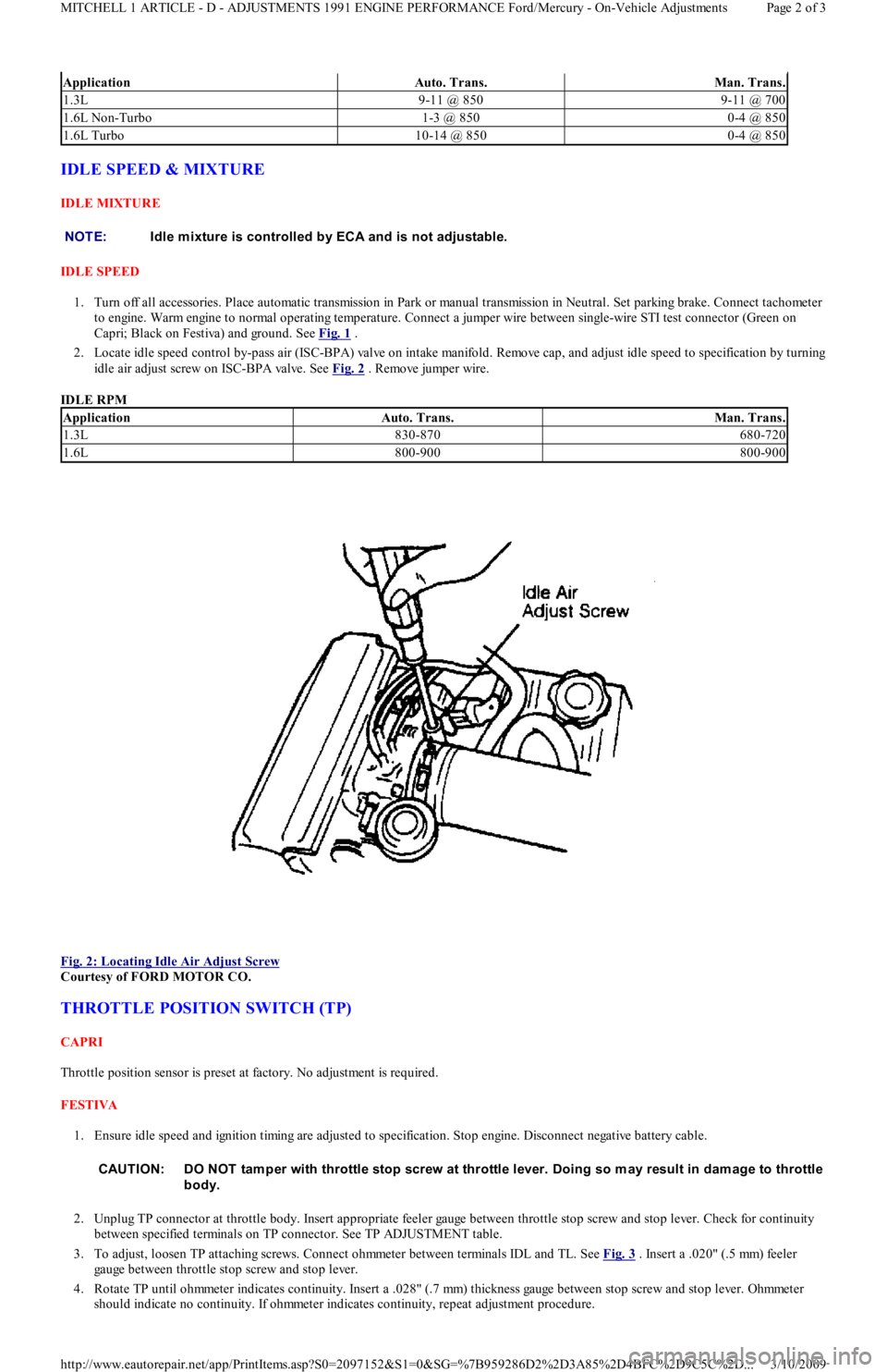
2. Locate idle speed control by-pass air (ISC-BPA) valve on intake manifold. Remove cap, and adjust idle speed to specification by turning
idle air adjust screw on ISC-BPA valve. See Fig. 2
. Remove jumper wire.
IDLE RPM
Fig. 2: Locating Idle Air Adjust Screw
Courtesy of FORD MOTOR CO.
THROTTLE POSITION SWITCH (TP)
CAPRI
Throttle position sensor is preset at factory. No adjustment is required.
FESTIVA
1. Ensure idle speed and ignition timing are adjusted to specification. Stop engine. Disconnect negative battery cable.
2. Unplug TP connector at throttle body. Insert appropriate feeler gauge between throttle stop screw and stop lever. Check for continuity
between specified terminals on TP connector. See TP ADJUSTMENT table.
3. To adjust, loosen TP attaching screws. Connect ohmmeter between terminals IDL and TL. See Fig. 3
. Insert a .020" (.5 mm) feeler
gauge between throttle stop screw and stop lever.
4. Rotate TP until ohmmeter indicates continuity. Insert a .028" (.7 mm) thickness gauge between stop screw and stop lever. Ohmmeter
should indicate no continuity. If ohmmeter indicates continuity, repeat adjustment procedure.
ApplicationAuto. Trans.Man. Trans.
1.3L9-11 @ 8509-11 @ 700
1.6L Non-Turbo1-3 @ 8500-4 @ 850
1.6L Turbo10-14 @ 8500-4 @ 850
NOTE:Idle m ixture is controlled by ECA and is not adjustable.
ApplicationAuto. Trans.Man. Trans.
1.3L830-870680-720
1.6L800-900800-900
CAUT ION: DO NOT tam per with throttle stop screw at throttle lever. Doing so m ay result in dam age to throttle
body.
Page 2 of 3 MITCHELL 1 ARTICLE - D - ADJUSTMENTS 1991 ENGINE PERFORMANCE Ford/Mercury - On-Vehicle Adjustments
3/10/2009 http://www.eautorepair.net/app/PrintItems.asp?S0=2097152&S1=0&SG=%7B959286D2%2D3A85%2D4BFC%2D9C5C%2D
...
Page 169 of 454
memory. Intermittent failures may be caused by a sensor, connector, or wiring. See INTERMITTENTS in TESTS W/O CODES article in the
ENGINE PERFORMANCE Section.
VISUAL CHECK & VEHICLE PREPARATION
Before connecting any equipment to diagnose EEC system, perform following preparatory procedures:
Verify condition of air cleaner and air ducts.
Check all vacuum hoses for leaks, restrictions, or improper routing.
Check EEC system wiring harness electrical connections for corrosion, bent or broken pins, loose wires or terminals, or improper
routing.
Check ECA, sensors, and actuators for physical damage.
Check engine oil and coolant level.
Perform all necessary safety precautions to prevent personal injury or vehicle damage.
Set parking brake. Place shift lever in Park for automatic transmissions, or Neutral for manual transmissions. DO NOT move shift lever
during test unless specifically directed.
Turn off all lights and accessories. Ensure vehicle doors are closed when measuring voltage or resistance.
Start engine. Run at idle until upper radiator hose is hot and pressurized and engine is off fast idle. Check for leaks around exhaust
manifold, exhaust gas oxygen sensor, and vacuum hose connections.
Turn ignition off. Service items as required. Go to EQUIPMENT HOOK-UP .
EQUIPMENT HOOK-UP
VOM
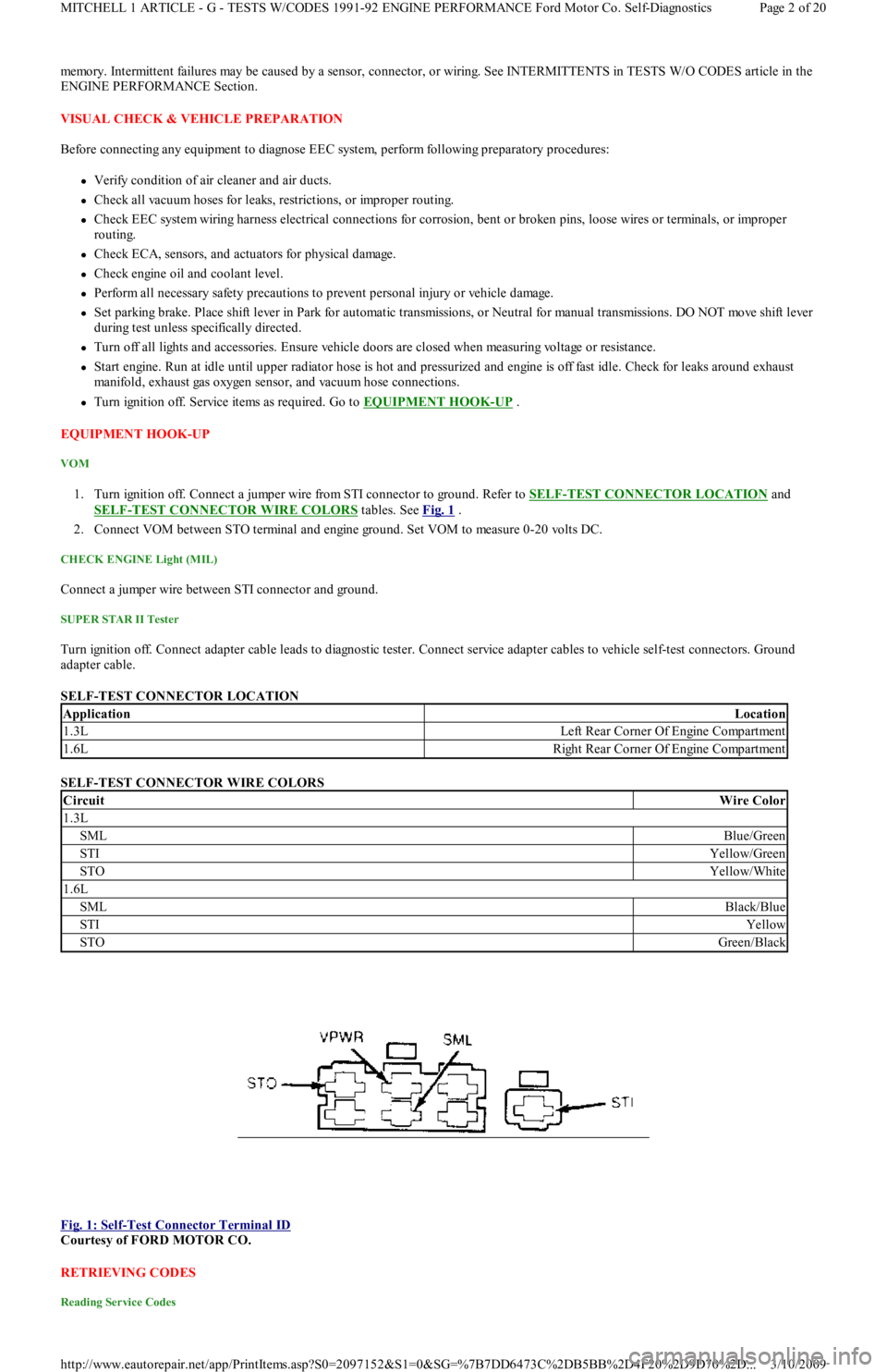
1. Turn ignition off. Connect a jumper wire from STI connector to ground. Refer to SELF-TEST CONNECTOR LOCATION and
SELF
-TEST CONNECTOR WIRE COLORS tables. See Fig. 1 .
2. Connect VOM between STO terminal and engine ground. Set VOM to measure 0-20 volts DC.
CHECK ENGINE Light (MIL)
Connect a jumper wire between STI connector and ground.
SUPER STAR II Tester
Turn ignition off. Connect adapter cable leads to diagnostic tester. Connect service adapter cables to vehicle self-test connectors. Ground
adapter cable.
SELF-TEST CONNECTOR LOCATION
SELF-TEST CONNECTOR WIRE COLORS
Fig. 1: Self
-Test Connector Terminal ID
Courtesy of FORD MOTOR CO.
RETRIEVING CODES
Reading Service Codes
ApplicationLocation
1.3LLeft Rear Corner Of Engine Compartment
1.6LRight Rear Corner Of Engine Compartment
CircuitWire Color
1.3L
SMLBlue/Green
STIYellow/Green
STOYellow/White
1.6L
SMLBlack/Blue
STIYellow
STOGreen/Black
Page 2 of 20 MITCHELL 1 ARTICLE - G - TESTS W/CODES 1991-92 ENGINE PERFORMANCE Ford Motor Co. Self-Diagnostics
3/10/2009 http://www.eautorepair.net/app/PrintItems.asp?S0=2097152&S1=0&SG=%7B7DD6473C%2DB5BB%2D4F20%2D9D70%2D
...