lug pattern FORD FESTIVA 1991 Service Manual
[x] Cancel search | Manufacturer: FORD, Model Year: 1991, Model line: FESTIVA, Model: FORD FESTIVA 1991Pages: 454, PDF Size: 9.53 MB
Page 235 of 454

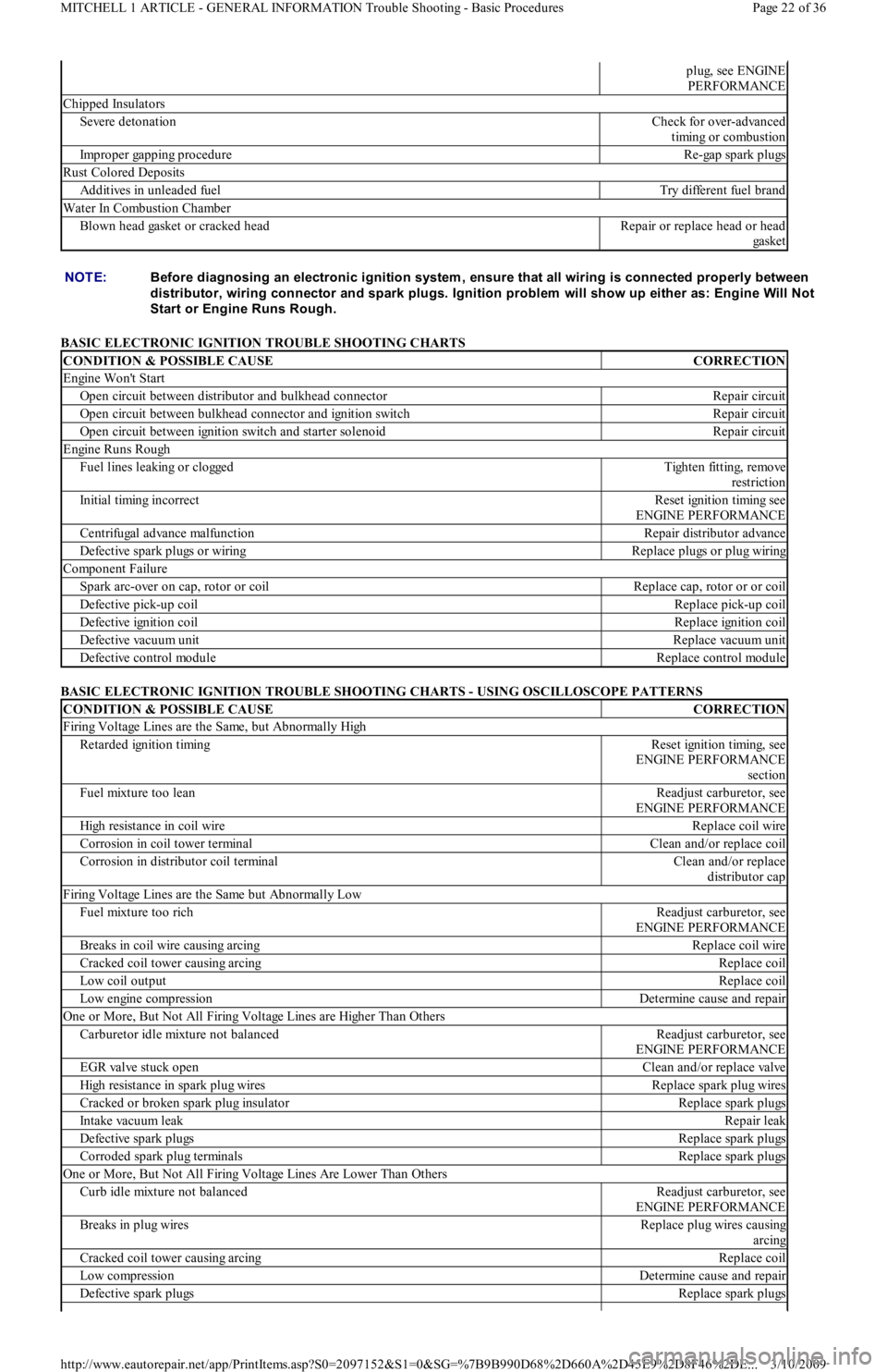
BASIC ELECTRONIC IGNITION TROUBLE SHOOTING CHARTS
BASIC ELECTRONIC IGNITION TROUBLE SHOOTING CHARTS - USING OSCILLOSCOPE PATTERNS
plug, see ENGINE
PERFORMANCE
Chipped Insulators
Severe detonationCheck for over-advanced
timing or combustion
Improper gapping procedureRe-gap spark plugs
Rust Colored Deposits
Additives in unleaded fuelTry different fuel brand
Water In Combustion Chamber
Blown head gasket or cracked headRepair or replace head or head
ga ske t
NOTE:Before diagnosing an electronic ignition system , ensure that all wiring is connected properly between
distributor, wiring connector and spark plugs. Ignition problem will show up either as: Engine Will Not
Start or Engine Runs Rough.
CONDITION & POSSIBLE CAUSECORRECTION
Engine Won't Start
Open circuit between distributor and bulkhead connectorRepair circuit
Open circuit between bulkhead connector and ignition switchRepair circuit
Open circuit between ignition switch and starter solenoidRepair circuit
Engine Runs Rough
Fuel lines leaking or cloggedTigh t e n fit t in g, r e mo ve
restriction
Initial timing incorrectReset ignition timing see
ENGINE PERFORMANCE
Centrifugal advance malfunctionRepair distributor advance
Defective spark plugs or wiringReplace plugs or plug wiring
Component Failure
Spark arc-over on cap, rotor or coilReplace cap, rotor or or coil
Defective pick-up coilReplace pick-up coil
Defective ignition coilReplace ignition coil
Defective vacuum unitReplace vacuum unit
Defective control moduleReplace control module
CONDITION & POSSIBLE CAUSECORRECTION
Firing Voltage Lines are the Same, but Abnormally High
Retarded ignition timingReset ignition timing, see
ENGINE PERFORMANCE
section
Fuel mixture too leanReadjust carburetor, see
ENGINE PERFORMANCE
High resistance in coil wireReplace coil wire
Corrosion in coil tower terminalClean and/or replace coil
Corrosion in distributor coil terminalClean and/or replace
distributor cap
Firing Voltage Lines are the Same but Abnormally Low
Fuel mixture too richReadjust carburetor, see
ENGINE PERFORMANCE
Breaks in coil wire causing arcingReplace coil wire
Cracked coil tower causing arcingReplace coil
Low coil outputReplace coil
Low engine compressionDetermine cause and repair
One or More, But Not All Firing Voltage Lines are Higher Than Others
Carburetor idle mixture not balancedReadjust carburetor, see
ENGINE PERFORMANCE
EGR valve stuck openClean and/or replace valve
High resistance in spark plug wiresReplace spark plug wires
Cracked or broken spark plug insulatorReplace spark plugs
Intake vacuum leakRepair leak
Defective spark plugsReplace spark plugs
Corroded spark plug terminalsReplace spark plugs
One or More, But Not All Firing Voltage Lines Are Lower Than Others
Curb idle mixture not balancedReadjust carburetor, see
ENGINE PERFORMANCE
Breaks in plug wiresReplace plug wires causing
arcing
Cracked coil tower causing arcingReplace coil
Low compressionDetermine cause and repair
Defective spark plugsReplace spark plugs
Page 22 of 36 MITCHELL 1 ARTICLE - GENERAL INFORMATION Trouble Shooting - Basic Procedures
3/10/2009 http://www.eautorepair.net/app/PrintItems.asp?S0=2097152&S1=0&SG=%7B9B990D68%2D660A%2D45E9%2D8F46%2DE
...
Page 250 of 454

Back To Article
GENERAL INFORMATION
T ROUBLE SHOOT ING
* PLEASE READ THIS FIRST *
ENGINE PERFORMANCE
TUNE-UP TROUBLE SHOOTING NOTE:T his article is generic in nature and all inform ation does not apply to all vehicles. For vehicle specific
inform ation, see the appropriate articles in the ENGINE PERFORMANCE category.
NOTE:T his article is generic in nature and all inform ation does not apply to all vehicles. For vehicle specific
inform ation, see the appropriate articles in the ENGINE PERFORMANCE category.
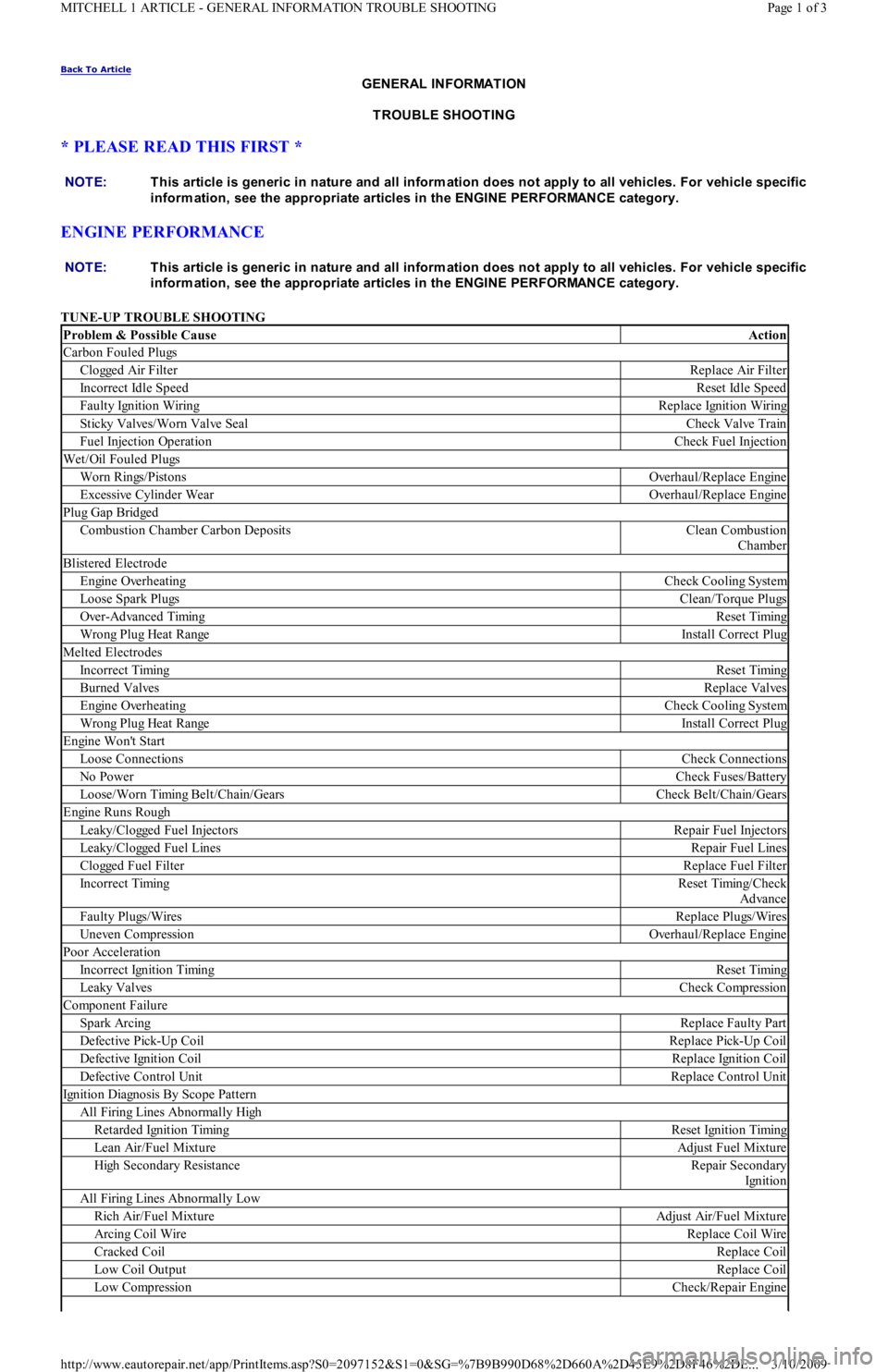
Problem & Possible CauseAction
Carbon Fouled Plugs
C l o gge d Air Fil t e rReplace Air Filter
Incorrect Idle SpeedReset Idle Speed
Faulty Ignition WiringReplace Ignition Wiring
Sticky Valves/Worn Valve SealCheck Valve Train
Fuel Injection OperationCheck Fuel Injection
Wet/Oil Fouled Plugs
Worn Rings/PistonsOverhaul/Replace Engine
Excessive Cylinder WearOverhaul/Replace Engine
Plug Gap Bridged
Combustion Chamber Carbon DepositsClean Combustion
Chamber
Blistered Electrode
Engine OverheatingCheck Cooling System
Loose Spark PlugsClean/Torque Plugs
Over-Advanced TimingReset Timing
Wrong Plug Heat RangeInstall Correct Plug
Melted Electrodes
Incorrect TimingReset Timing
Burned ValvesReplace Valves
Engine OverheatingCheck Cooling System
Wrong Plug Heat RangeInstall Correct Plug
Engine Won't Start
Loose ConnectionsCheck Connections
No PowerCheck Fuses/Battery
Loose/Worn Timing Belt/Chain/GearsCheck Belt/Chain/Gears
Engine Runs Rough
Leaky/Clogged Fuel InjectorsRepair Fuel Injectors
Leaky/Clogged Fuel LinesRepair Fuel Lines
Clogged Fuel FilterReplace Fuel Filter
Incorrect TimingReset Timing/Check
Advance
Faulty Plugs/WiresReplace Plugs/Wires
Uneven CompressionOverhaul/Replace Engine
Poor Acceleration
Incorrect Ignition TimingReset Timing
Leaky ValvesCheck Compression
Component Failure
Spark ArcingReplace Faulty Part
Defective Pick-Up CoilReplace Pick-Up Coil
Defective Ignition CoilReplace Ignition Coil
Defective Control UnitReplace Control Unit
Ignition Diagnosis By Scope Pattern
All Firing Lines Abnormally High
Retarded Ignition TimingReset Ignition Timing
Lean Air/Fuel MixtureAdjust Fuel Mixture
High Secondary ResistanceRepair Secondary
Ign it io n
All Firing Lines Abnormally Low
Rich Air/Fuel MixtureAdjust Air/Fuel Mixture
Arcing Coil WireReplace Coil Wire
Cracked CoilReplace Coil
Low Coil OutputReplace Coil
Low CompressionCheck/Repair Engine
Page 1 of 3 MITCHELL 1 ARTICLE - GENERAL INFORMATION TROUBLE SHOOTING
3/10/2009 http://www.eautorepair.net/app/PrintItems.asp?S0=2097152&S1=0&SG=%7B9B990D68%2D660A%2D45E9%2D8F46%2DE
...
Page 283 of 454

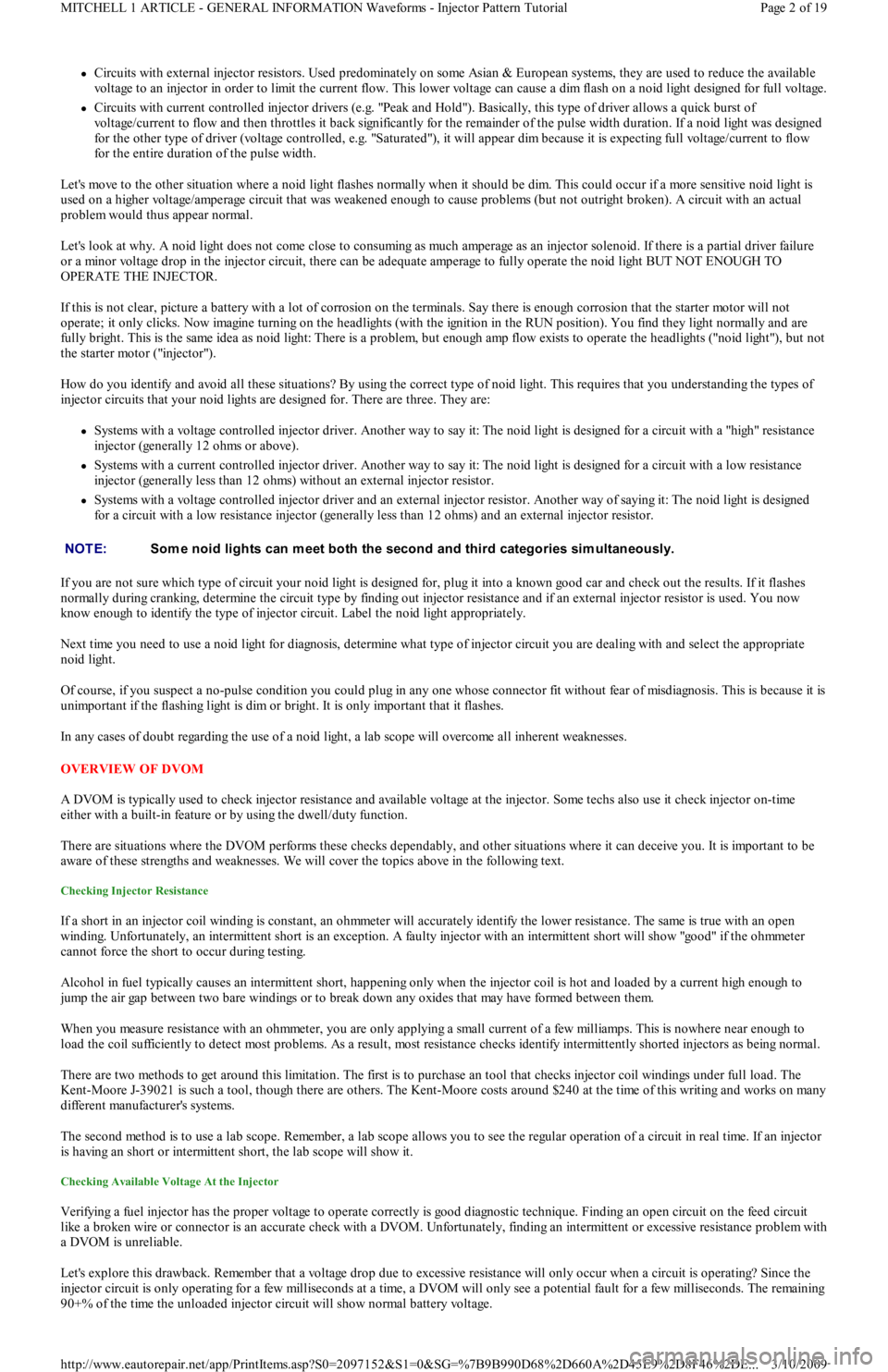
Circuits with external injector resistors. Used predominately on some Asian & European systems, they are used to reduce the available
voltage to an injector in order to limit the current flow. This lower voltage can cause a dim flash on a noid light designed for full voltage.
Circuits with current controlled injector drivers (e.g. "Peak and Hold"). Basically, this type of driver allows a quick burst of
voltage/current to flow and then throttles it back significantly for the remainder of the pulse width duration. If a noid light was designed
for the other type of driver (voltage controlled, e.g. "Saturated"), it will appear dim because it is expecting full voltage/current to flow
for the entire duration of the pulse width.
Let's move to the other situation where a noid light flashes normally when it should be dim. This could occur if a more sensitive n o id l igh t is
used on a higher voltage/amperage circuit that was weakened enough to cause problems (but not outright broken). A circuit with an actual
problem would thus appear normal.
Let's look at why. A noid light does not come close to consuming as much amperage as an injector solenoid. If there is a partial driver failure
or a minor voltage drop in the injector circuit, there can be adequate amperage to fully operate the noid light BUT NOT ENOUGH TO
OPERATE THE INJECTOR.
If this is not clear, picture a battery with a lot of corrosion on the terminals. Say there is enough corrosion that the starter motor will not
operate; it only clicks. Now imagine turning on the headlights (with the ignition in the RUN position). You find they light normally and are
fully bright. This is the same idea as noid light: There is a problem, but enough amp flow exists to operate the headlights ("noid light"), but not
the starter motor ("injector").
How do you identify and avoid all these situations? By using the correct type of noid light. This requires that you understanding the types of
injector circuits that your noid lights are designed for. There are three. They are:
Systems with a voltage controlled injector driver. Another way to say it: The noid light is designed for a circuit with a "high" resistance
injector (generally 12 ohms or above).
Systems with a current controlled injector driver. Another way to say it: The noid light is designed for a circuit with a low resistance
injector (generally less than 12 ohms) without an external injector resistor.
Systems with a voltage controlled injector driver and an external injector resistor. Another way of saying it: The noid light is designed
for a circuit with a low resistance injector (generally less than 12 ohms) and an external injector resistor.
If you are not sure which type of circuit your noid light is designed for, plug it into a known good car and check out the results. If it flashes
normally during cranking, determine the circuit type by finding out injector resistance and if an external injector resistor is used. You now
know enough to identify the type of injector circuit. Label the noid light appropriately.
Next time you need to use a noid light for diagnosis, determine what type of injector circuit you are dealing with and select the appropriate
noid light.
Of course, if you suspect a no-pulse condition you could plug in any one whose connector fit without fear of misdiagnosis. This is because it is
unimportant if the flashing light is dim or bright. It is only important that it flashes.
In any cases of doubt regarding the use of a noid light, a lab scope will overcome all inherent weaknesses.
OVERVIEW OF DVOM
A DVOM is typically used to check injector resistance and available voltage at the injector. Some techs also use it check injector on-time
either with a built-in feature or by using the dwell/duty function.
There are situations where the DVOM performs these checks dependably, and other situations where it can deceive you. It is important to be
aware of these strengths and weaknesses. We will cover the topics above in the following text.
Checking Injector Resistance
If a short in an injector coil winding is constant, an ohmmeter will accurately identify the lower resistance. The same is true with an open
winding. Unfortunately, an intermittent short is an exception. A faulty injector with an intermittent short will show "good" if the ohmmeter
cannot force the short to occur during testing.
Alcohol in fuel typically causes an intermittent short, happening only when the injector coil is hot and loaded by a current high e n o u gh t o
jump the air gap between two bare windings or to break down any oxides that may have formed between them.
When you measure resistance with an ohmmeter, you are only applying a small current of a few milliamps. This is nowhere near enough to
load the coil sufficiently to detect most problems. As a result, most resistance checks identify intermittently shorted injectors as being normal.
There are two methods to get around this limitation. The first is to purchase an tool that checks injector coil windings under full load. The
Kent-Moore J-39021 is such a tool, though there are others. The Kent-Moore costs around $240 at the time of this writing and works on many
different manufacturer's systems.
The second method is to use a lab scope. Remember, a lab scope allows you to see the regular operation of a circuit in real time. If an injector
is having an short or intermittent short, the lab scope will show it.
Checking Available Voltage At the Injector
Verifying a fuel injector has the proper voltage to operate correctly is good diagnostic technique. Finding an open circuit on the feed circuit
like a broken wire or connector is an accurate check with a DVOM. Unfortunately, finding an intermittent or excessive resistance problem with
a DVOM is unreliable.
Let's explore this drawback. Remember that a voltage drop due to excessive resistance will only occur when a circuit is operating? Since the
injector circuit is only operating for a few milliseconds at a time, a DVOM will only see a potential fault for a few milliseconds. The remaining
90+% of the time the unloaded injector circuit will show normal battery voltage. NOTE:Som e noid lights can m eet both the second and third categories sim ultaneously.
Page 2 of 19 MITCHELL 1 ARTICLE - GENERAL INFORMATION Waveforms - Injector Pattern Tutorial
3/10/2009 http://www.eautorepair.net/app/PrintItems.asp?S0=2097152&S1=0&SG=%7B9B990D68%2D660A%2D45E9%2D8F46%2DE
...