torque FORD FIESTA 1989 Service Repair Manual
[x] Cancel search | Manufacturer: FORD, Model Year: 1989, Model line: FIESTA, Model: FORD FIESTA 1989Pages: 296, PDF Size: 10.65 MB
Page 243 of 296
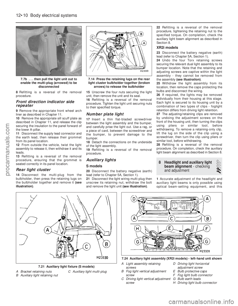
8Refitting is a reversal of the removal
procedure.
Front direction indicator side
repeater
9 Remove the appropriate front wheel arch
liner as described in Chapter 11.
10 Remove the appropriate sill scuff plate as
described in Chapter 11, and release the clip
securing the insulation to the panel forward of
the lower A-pillar.
11 Disconnect the supply lead connector and
the earth lead, then release their grommet
from its panel location.
12 From outside the vehicle, twist the light
assembly to release it, then withdraw it and its
leads.
13 Refitting is a reversal of the removal
procedure, ensuring that the grommet is
seated correctly in its panel location.
Rear light cluster
14 Disconnect the multi-plug from the
bulbholder, then press the retaining lugs on
the bulbholder together and remove it (see
illustration) . 15
Unscrew the four nuts securing the light
unit, then remove the unit and its seal.
16 Refitting is a reversal of the removal
procedure. Tighten the light unit securing nuts
to their specified torque.
Number plate light
17 Insert a thin flat-bladed screwdriver
between the light assembly and the bumper,
and carefully prise the light out. Use a rag, or
a piece of card, between the screwdriver and
the bumper, to prevent damage to the
bumper.
18 Detach the connections on the underside
of the light assembly.
19 Refitting is a reversal of the removal
procedure.
Auxiliary lights
S models
20 Disconnect the battery negative (earth)
lead (refer to Chapter 5A, Section 1).
21 Disconnect the light wiring multi-plug then
unscrew its retaining nut, withdraw the bolt
and remove the light unit (see illustration).22
Refitting is a reversal of the removal
procedure, tightening the retaining nut to the
specified torque. On completion, check the
auxiliary light beam alignment as described in
Section 8.
XR2i models
23 Disconnect the battery negative (earth)
lead (refer to Chapter 5A, Section 1).
24 Undo the four Torx retaining screws
securing the relevant dual light assembly to its
bumper location. Note that the retaining and
adjusting screws are captive within the light
assembly - they cannot be removed from
the assembly (see illustration) .
25 Withdraw the light assembly from its
location, then remove the caps protecting the
bulbs and disconnect the wiring.
26 If required, the lights may be removed
individually from their housing at this stage.
Each light is secured to its housing unit by a
combination of two types of clips - foglight
retention differs from driving light retention.
27 The adjusting/retaining clips are removed
by undoing the adjustment screws on the
front of the housing unit, then turning the clips
using pliers or similar tool, before
withdrawing. To remove a retaining-only clip,
lift the lug on the side of the clip using a
screwdriver, then turn the clip using pliers or
similar tool, before withdrawing.
28 Refitting is a reversal of the removal
procedure. On completion, check the auxiliary
light beam alignment as described in Section 8.
8 Headlight and auxiliary light
beam alignment - checking
and adjustment
2
1 Accurate adjustment of the headlight and
auxiliary light beams is only possible using
optical beam-setting equipment, and this
12•10 Body electrical systems
7.24 Auxiliary light assembly (XR2i models) - left-hand unit shown
A Light assembly retaining screws
B Fog light vertical adjustment screw
C Driving light vertical adjustment screw D Driving light horizontal
adjustment screw
E Bulb protective caps
F Fog light bulb connector
G Bulb earth leads
H Driving light bulb connector
7.21 Auxiliary light fixture (S models)
A Bracket retaining nuts C Auxiliary light multi-plug
B Auxiliary light retaining nut
7.14 Press the retaining lugs on the rear
light cluster bulbholder together (broken arrows) to release the bulbholder7.7b . . . then pull the light unit out to
enable the multi-plug (arrowed) to be disconnected
1595Ford Fiesta Remakeprocarmanuals.com
http://vnx.su
Page 246 of 296

16 Windscreen wiper motor andlinkage - removal and refitting
2
Removal
Wiper motor
1Operate the wiper motor, then switch it off
so that it returns to its rest position.
2 Disconnect the battery negative (earth) lead
(refer to Chapter 5A, Section 1).
3 Dependent on model, disconnect and
remove the air cleaner components as
necessary to allow access to remove the
bulkhead panel.
4 Remove the cooling system expansion tank
as described in Chapter 3.
5 Release the wiring loom, any connectors,
cable-ties and hoses from the right-hand half
of the bulkhead panel, then remove its rubber
seal.
6 The right-hand half of the bulkhead panel is
secured by screws and a single nut. The nut is
located behind the panel at the bonnet hinge
end. Release the right-hand half of the panel
and, having ensured that it is free to move,
remove it (see illustrations) .
7 Unscrew the nut from the driving shaft, and
pull the crank off the driving shaft taper (see
illustration) .
8 Undo the three wiper motor retaining bolts and withdraw the motor assembly
(see
illustrations) . Remove the motor cover, then
disconnect the multi-plug and remove the
motor from the vehicle.
Linkage
9 Pull the rubber seal off the bulkhead panel.
10 Bring the windscreen wiper linkage to an
accessible position, using the ignition switch
as a means of stopping the wiper motor
returning to the parked position.
11 Disconnect the battery negative (earth)
lead (refer to Chapter 5A, Section 1).
12 Prise the linkages off their ball pivots as
required, using a suitably-sized open-ended
spanner. The crank has a dual (vertically
stacked) ball pivot with a bellows separating
the two linkages (see illustrations) .
13 If the running faces of the ball pivots are
damaged, the pivot shaft(s) or crank must be
renewed.
Refitting
Wiper motor
14 Refitting is a reversal of the removal
procedure, tightening all nuts and bolts to the
specified torque. Refit the expansion tank as
described in Chapter 3.
Linkage
15 Prior to refitting, grease the ball pivot
sockets on the linkages, then locate them on
their appropriate ball pivots and press into position using a suitably-sized socket. The
bellows between the two linkages on the
crank must also be greased using the
specified lubricant. Refit the bulkhead panel
rubber seal on completion.
17 Windscreen wiper pivot
shaft - removal and refitting
2
Removal
1Remove the windscreen wiper arms as
described in Section 15.
Body electrical systems 12•13
16.7 Unscrew the nut from the wiper motor driving shaft16.6b . . . then disengage the right-handhalf of the panel from under its single retaining nut (left-hand shown)16.6a Remove all retaining screws from
the right-hand half of the bulkhead panel (upper centre screw shown) . . .
16.12b Windscreen wiper motor bracketwith linkage and motor. Inset shows
bellows arrangement (A)
16.8a With the crank removed from the
driving shaft taper, undo the three wiper motor retaining bolts (arrowed)
16.12a Windscreen wiper linkage
A Removal B Refitting16.8b . . . and withdraw the wiper motor assembly
12
1595Ford Fiesta Remakeprocarmanuals.com
http://vnx.su
Page 247 of 296
2Carry out the procedure detailed in Sec-
tion 16, paragraphs 2 to 6.
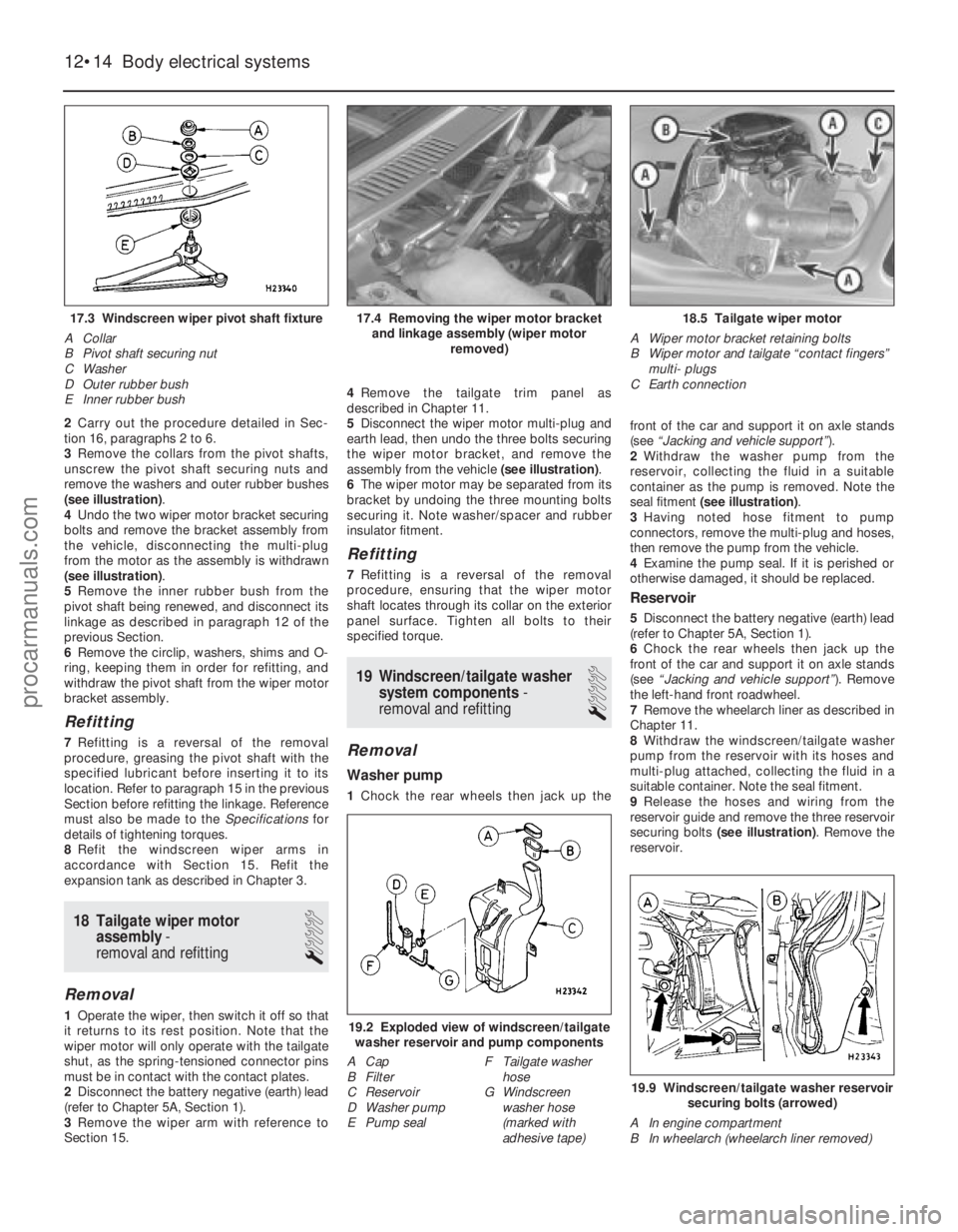
3 Remove the collars from the pivot shafts,
unscrew the pivot shaft securing nuts and
remove the washers and outer rubber bushes
(see illustration) .
4 Undo the two wiper motor bracket securing
bolts and remove the bracket assembly from
the vehicle, disconnecting the multi-plug
from the motor as the assembly is withdrawn
(see illustration) .
5 Remove the inner rubber bush from the
pivot shaft being renewed, and disconnect its
linkage as described in paragraph 12 of the
previous Section.
6 Remove the circlip, washers, shims and O-
ring, keeping them in order for refitting, and
withdraw the pivot shaft from the wiper motor
bracket assembly.
Refitting
7 Refitting is a reversal of the removal
procedure, greasing the pivot shaft with the
specified lubricant before inserting it to its
location. Refer to paragraph 15 in the previous
Section before refitting the linkage. Reference
must also be made to the Specificationsfor
details of tightening torques.
8 Refit the windscreen wiper arms in
accordance with Section 15. Refit the
expansion tank as described in Chapter 3.
18 Tailgate wiper motor assembly -
removal and refitting
1
Removal
1 Operate the wiper, then switch it off so that
it returns to its rest position. Note that the
wiper motor will only operate with the tailgate
shut, as the spring-tensioned connector pins
must be in contact with the contact plates.
2 Disconnect the battery negative (earth) lead
(refer to Chapter 5A, Section 1).
3 Remove the wiper arm with reference to
Section 15. 4
Remove the tailgate trim panel as
described in Chapter 11.
5 Disconnect the wiper motor multi-plug and
earth lead, then undo the three bolts securing
the wiper motor bracket, and remove the
assembly from the vehicle (see illustration).
6 The wiper motor may be separated from its
bracket by undoing the three mounting bolts
securing it. Note washer/spacer and rubber
insulator fitment.
Refitting
7 Refitting is a reversal of the removal
procedure, ensuring that the wiper motor
shaft locates through its collar on the exterior
panel surface. Tighten all bolts to their
specified torque.
19 Windscreen/tailgate washer system components -
removal and refitting
1
Removal
Washer pump
1 Chock the rear wheels then jack up the front of the car and support it on axle stands
(see
“Jacking and vehicle support” ).
2 Withdraw the washer pump from the
reservoir, collecting the fluid in a suitable
container as the pump is removed. Note the
seal fitment (see illustration) .
3 Having noted hose fitment to pump
connectors, remove the multi-plug and hoses,
then remove the pump from the vehicle.
4 Examine the pump seal. If it is perished or
otherwise damaged, it should be replaced.
Reservoir
5 Disconnect the battery negative (earth) lead
(refer to Chapter 5A, Section 1).
6 Chock the rear wheels then jack up the
front of the car and support it on axle stands
(see “Jacking and vehicle support” ). Remove
the left-hand front roadwheel.
7 Remove the wheelarch liner as described in
Chapter 11.
8 Withdraw the windscreen/tailgate washer
pump from the reservoir with its hoses and
multi-plug attached, collecting the fluid in a
suitable container. Note the seal fitment.
9 Release the hoses and wiring from the
reservoir guide and remove the three reservoir
securing bolts (see illustration) . Remove the
reservoir.
12•14 Body electrical systems
19.9 Windscreen/tailgate washer reservoir
securing bolts (arrowed)
A In engine compartment
B In wheelarch (wheelarch liner removed)
19.2 Exploded view of windscreen/tailgate washer reservoir and pump components
A Cap
B Filter
C Reservoir
D Washer pump
E Pump seal F Tailgate washer
hose
G Windscreen
washer hose
(marked with
adhesive tape)
18.5 Tailgate wiper motor
A Wiper motor bracket retaining bolts
B Wiper motor and tailgate “contact fingers” multi- plugs
C Earth connection17.4 Removing the wiper motor bracket and linkage assembly (wiper motor removed)17.3 Windscreen wiper pivot shaft fixture
A Collar
B Pivot shaft securing nut
C Washer
D Outer rubber bush
E Inner rubber bush
1595Ford Fiesta Remakeprocarmanuals.com
http://vnx.su
Page 270 of 296

1595 Ford Fiesta Remake
REF•4General repair procedures
Whenever servicing, repair or overhaul work
is carried out on the car or its components,
observe the following procedures and
instructions. This will assist in carrying out the
operation efficiently and to a professional
standar d of workmanship.
Joint mating faces and gaskets
When separating components at their
mating faces, never insert screwdrivers or
similar implements into the joint between the
faces in order to prise them apart. This can
cause severe damage which results in oil
leaks, coolant leaks, etc upon reassembly.
Separation is usually achieved by tapping
along the joint with a soft-faced hammer in
or der to break the seal. However, note that
this method may not be suitable where
dowels are used for component location.
Wher e a gasket is used between the mating
faces of two components, a new one must be
fitted on reassembly; fit it dry unless otherwise
stated in the repair procedure. Make sure that
the mating faces are clean and dry, with all
traces of old gasket removed. When cleaning a
joint face, use a tool which is unlikely to score
or damage the face, and remove any burrs or
nicks with an oilstone or fine file.
Make sure that tapped holes are cleaned
with a pipe cleaner, and keep them free of
jointing compound, if this is being used,
unless specifically instructed otherwise. Ensur e that all orifices, channels or pipes
ar e clear, and blow through them, preferably
using compressed air.
Oil seals
Oil seals can be removed by levering them
out with a wide flat-bladed screwdriver or
similar implement. Alternatively, a number of
self-tapping screws may be screwed into the
seal, and these used as a purchase for pliers or
some similar device in order to pull the seal free.
Whenever an oil seal is removed from its
working location, either individually or as part
of an assembly, it should be renewed. The very fine sealing lip of the seal is easily
damaged, and will not seal if the surface it
contacts is not completely clean and free fr om
scratches, nicks or grooves. If the original
sealing surface of the component cannot be
restor ed, and the manufacturer has not made
pr ovision for slight relocation of the seal
r elative to the sealing surface, the component
should be renewed.
Protect the lips of the seal from any surface
which may damage them in the course of
fitting. Use tape or a conical sleeve where
possible. Lubricate the seal lips with oil before
fitting and, on dual-lipped seals, fill the space
between the lips with grease.
Unless otherwise stated, oil seals must be
fitted with their sealing lips toward the
lubricant to be sealed.
Use a tubular drift or block of wood of the
appr opriate size to install the seal and, if the
seal housing is shouldered, drive the seal
down to the shoulder. If the seal housing is unshoulder
ed, the seal should be fitted with
its face flush with the housing top face (unless
otherwise instructed).
Screw threads and fastenings
Seized nuts, bolts and screws are quite a
common occurrence where corrosion has set
in, and the use of penetrating oil or releasing
fluid will often overcome this problem if the
of fending item is soaked for a while before
attempting to release it. The use of an impact
driver may also provide a means of releasing
such stubborn fastening devices, when used
in conjunction with the appropriate
scr ewdriver bit or socket. If none of these
methods works, it may be necessary to resort
to the careful application of heat, or the use of
a hacksaw or nut splitter device. Studs are usually removed by locking two
nuts together on the threaded part, and then
using a spanner on the lower nut to unscrew
the stud. Studs or bolts which have broken off
below the surface of the component in which
they are mounted can sometimes be removed
using a stud extractor. Always ensure that a
blind tapped hole is completely free from oil,
gr ease, water or other fluid before installing
the bolt or stud. Failure to do this could cause
the housing to crack due to the hydraulic
action of the bolt or stud as it is screwed in. When tightening a castellated nut to accept
a split pin, tighten the nut to the specified
tor que, where applicable, and then tighten
further to the next split pin hole. Never slacken
the nut to align the split pin hole, unless stated
in the repair procedure.
When checking or retightening a nut or bolt
to a specified torque setting, slacken the nut
or bolt by a quarter of a turn, and then
r etighten to the specified setting. However,
this should not be attempted where angular
tightening has been used. For some screw fastenings, notably
cylinder head bolts or nuts, torque wrench
settings are no longer specified for the latter
stages of tightening, “angle-tightening” being
called up instead. Typically, a fairly low torque wr ench setting will be applied to the
bolts/nuts in the correct sequence, followed
by one or more stages of tightening through
specified angles.
Locknuts, locktabs and washers
Any fastening which will rotate against a
component or housing during tightening
should always have a washer between it and
the relevant component or housing. Spring or split washers should always be
r enewed when they are used to lock a critical
component such as a big-end bearing
r etaining bolt or nut. Locktabs which are
folded over to retain a nut or bolt should
always be renewed.
Self-locking nuts can be re-used in non-
critical areas, providing resistance can be felt
when the locking portion passes over the bolt
or stud thread. However, it should be noted
that self-locking stiffnuts tend to lose their ef
fectiveness after long periods of use, and
should then be renewed as a matter of course.
Split pins must always be replaced with
new ones of the correct size for the hole. When thread-locking compound is found
on the threads of a fastener which is to be re-
used, it should be cleaned off with a wire
brush and solvent, and fresh compound
applied on reassembly.
Special tools
Some repair procedures in this manual
entail the use of special tools such as a press,
two or three-legged pullers, spring com-
pr essors, etc. Wherever possible, suitable
readily-available alternatives to the manu-
facturer’ s special tools are described, and are
shown in use. In some instances, where no
alter native is possible, it has been necessary
to resort to the use of a manufacturer’s tool, and this has been done for reasons of safety
as well as the efficient completion of the repair
operation. Unless you are highly-skilled and
have a thorough understanding of the
procedur es described, never attempt to
bypass the use of any special tool when the
pr ocedur e described specifies its use. Not
only is there a very great risk of personal
injury , but expensive damage could be
caused to the components involved.
Environmental considerations
When disposing of used engine oil, brake
fluid, antifreeze, etc, give due consideration to
any detrimental environmental effects. Do not,
for instance, pour any of the above liquids
down drains into the general sewage system,
or onto the ground to soak away. Many local
council refuse tips provide a facility for waste
oil disposal, as do some garages. If none of
these facilities are available, consult your local
Envir onmental Health Department, or the
National Rivers Authority, for further advice. With the universal tightening-up of legis-
lation regarding the emission of environmen-
tally-harmful substances from motor vehicles,
most vehicles have tamperproof devices fitted
to the main adjustment points of the fuel
system. These devices are primarily designed
to prevent unqualified persons from adjusting the fuel/air mixture, with the chance of a
consequent increase in toxic emissions. If
such devices are found during servicing or
overhaul, they should, wherever possible, be
r enewed or refitted in accordance with the
manufacturer’ s requirements or current
legislation.
Note: It is
antisocial and
illegal to dump
oil down the
drain. To find
the location of
your local oil
recycling
bank, call this
number free.
procarmanuals.com
http://vnx.su
Page 272 of 296
REF•6Conversion Factors
1595 Ford Fiesta Remake
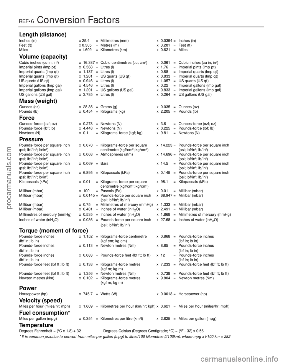
Length (distance)
Inches (in)x 25.4 = Millimetres (mm) x 0.0394 = Inches (in)
Feet (ft) x 0.305 = Metres (m) x 3.281 = Feet (ft)
Miles x 1.609 = Kilometres (km) x 0.621 = Miles
Volume (capacity)
Cubic inches (cu in; in3)x 16.387 = Cubic centimetres (cc; cm3) x 0.061 = Cubic inches (cu in; in3)
Imperial pints (Imp pt) x 0.568 = Litres (l) x 1.76 = Imperial pints (Imp pt)
Imperial quarts (Imp qt) x 1.137 = Litres (l) x 0.88 = Imperial quarts (Imp qt)
Imperial quarts (Imp qt) x 1.201 = US quarts (US qt) x 0.833 = Imperial quarts (Imp qt)
US quarts (US qt) x 0.946 = Litres (l) x 1.057 = US quarts (US qt)
Imperial gallons (Imp gal) x 4.546 = Litres (l) x 0.22 = Imperial gallons (Imp gal)
Imperial gallons (Imp gal) x 1.201 = US gallons (US gal) x 0.833 = Imperial gallons (Imp gal)
US gallons (US gal) x 3.785 = Litres (l) x 0.264 = US gallons (US gal)
Mass (weight)
Ounces (oz)x 28.35 = Grams (g) x 0.035 = Ounces (oz)
Pounds (lb) x 0.454 = Kilograms (kg) x 2.205 = Pounds (lb)
Force
Ounces-force (ozf; oz)x 0.278 = Newtons (N) x 3.6 = Ounces-force (ozf; oz)
Pounds-force (lbf; lb) x 4.448 = Newtons (N) x 0.225 = Pounds-force (lbf; lb)
Newtons (N) x 0.1 = Kilograms-force (kgf; kg) x 9.81 = Newtons (N)
Pressure
Pounds-force per square inch x 0.070 = Kilograms-force per square x 14.223 = Pounds-force per square inch
(psi; lbf/in2; lb/in2)centimetre (kgf/cm2; kg/cm2)(psi; lbf/in2; lb/in2)
Pounds-force per square inch x 0.068 = Atmospheres (atm) x 14.696 = Pounds-force per square inch
(psi; lbf/in
2; lb/in2) (psi; lbf/in2; lb/in2)
Pounds-force per square inch x 0.069 = Bars x 14.5 = Pounds-force per square inch
(psi; lbf/in
2; lb/in2) (psi; lbf/in2; lb/in2)
Pounds-force per square inch x 6.895 = Kilopascals (kPa) x 0.145 = Pounds-force per square inch
(psi; lbf/in
2; lb/in2) (psi; lbf/in2; lb/in2)
Kilopascals (kPa) x 0.01 = Kilograms-force per square x 98.1 = Kilopascals (kPa)
centimetre (kgf/cm
2; kg/cm2)
Millibar (mbar) x 100 = Pascals (Pa) x 0.01 = Millibar (mbar)
Millibar (mbar) x 0.0145 = Pounds-force per square inch x 68.947 = Millibar (mbar)
(psi; lbf/in
2; lb/in2)
Millibar (mbar) x 0.75 = Millimetres of mercury (mmHg) x 1.333 = Millibar (mbar)
Millibar (mbar) x 0.401 = Inches of water (inH
2O) x 2.491 = Millibar (mbar)
Millimetres of mercury (mmHg) x 0.535 = Inches of water (inH
2O) x 1.868 = Millimetres of mercury (mmHg)
Inches of water (inH
2O) x 0.036 = Pounds-force per square inch x 27.68 = Inches of water (inH2O)
(psi; lbf/in2; lb/in2)
Torque (moment of force)
Pounds-force inches x 1.152 = Kilograms-force centimetre x 0.868 = Pounds-force inches
(lbf in; lb in) (kgf cm; kg cm)(lbf in; lb in)
Pounds-force inches x 0.113 = Newton metres (Nm) x 8.85 = Pounds-force inches
(lbf in; lb in) (lbf in; lb in)
Pounds-force inches x 0.083 = Pounds-force feet (lbf ft; lb ft) x 12 =Pounds-force inches
(lbf in; lb in) (lbf in; lb in)
Pounds-force feet (lbf ft; lb ft) x 0.138 = Kilograms-force metres x 7.233 = Pounds-force feet (lbf ft; lb ft) (kgf m; kg m)
Pounds-force feet (lbf ft; lb ft) x 1.356 = Newton metres (Nm) x 0.738 = Pounds-force feet (lbf ft; lb ft)
Newton metres (Nm) x 0.102 = Kilograms-force metres x 9.804 = Newton metres (Nm)
(kgf m; kg m)
Power
Horsepower (hp) x 745.7 = Watts (W) x 0.0013 = Horsepower (hp)
Velocity (speed)
Miles per hour (miles/hr; mph) x 1.609 = Kilometres per hour (km/hr; kph) x 0.621 = Miles per hour (miles/hr; mph)
Fuel consumption*
Miles per gallon (mpg)x 0.354 = Kilometres per litre (km/l) x 2.825 = Miles per gallon (mpg)
Temperature
Degrees Fahrenheit = (°C x 1.8) + 32 Degrees Celsius (Degrees Centigrade; °C) = (°F - 32) x 0.56
* It is common practice to convert from miles per gallon (mpg) to litr\
es/100 kilometres (l/100km), where mpg x l/100 km = 282
procarmanuals.com
http://vnx.su
Page 273 of 296
Introduction
A selection of good tools is a fundamental
requirement for anyone contemplating the
maintenance and repair of a motor vehicle.
For the owner who does not possess any,
their purchase will prove a considerable
expense, offsetting some of the savings made
by doing-it-yourself. However, provided that
the tools purchased meet the relevant national
safety standards and are of good quality, they
will last for many years and prove an
extremely worthwhile investment. To help the average owner to decide which
tools are needed to carry out the various tasks
detailed in this manual, we have compiled
three lists of tools under the following
headings: Maintenance and minor repair,
Repair and overhaul , and Special. Newcomers
to practical mechanics should start off with
the Maintenance and minor repair tool kit, and
confine themselves to the simpler jobs around
the vehicle. Then, as confidence and
experience grow, more difficult tasks can be
undertaken, with extra tools being purchased
as, and when, they are needed. In this way, a
Maintenance and minor repair tool kit can be
built up into a Repair and overhaul tool kit over
a considerable period of time, without any
major cash outlays. The experienced do-it-
yourselfer will have a tool kit good enough for
most repair and overhaul procedures, and will
add tools from the Specialcategory when it is
felt that the expense is justified by the amount
of use to which these tools will be put.
Maintenance and minor repair
tool kit
The tools given in this list should be
considered as a minimum requirement if
routine maintenance, servicing and minor
repair operations are to be undertaken. We
recommend the purchase of combination
spanners (ring one end, open-ended the
other); although more expensive than open-
ended ones, they do give the advantages of
both types of spanner.
M Combination spanners: 8, 9, 10, 11, 12, 13,
14, 15, 16, 17, 19, 21, 22, 24 & 26 mm
M Adjustable spanner - 35 mm jaw (approx)
M Engine sump/gearbox drain plug key
(where applicable)
M Set of feeler gauges
M Spark plug spanner (with rubber insert)
M Spark plug gap adjustment tool
M Brake bleed nipple spanner
M Screwdrivers: Flat blade and cross blade –
approx 100 mm long x 6 mm dia
M Combination pliers
M Hacksaw (junior)
M Tyre pump
M Tyre pressure gauge
M Grease gun
M Oil can
M Oil filter removal tool
M Fine emery cloth
M Wire brush (small)
M Funnel (medium size)
Repair and overhaul tool kit
These tools are virtually essential for
anyone undertaking any major repairs to a
motor vehicle, and are additional to those
given in the Maintenance and minor repair list.
Included in this list is a comprehensive set of
sockets. Although these are expensive, they
will be found invaluable as they are so
versatile - particularly if various drives are
included in the set. We recommend the half-
inch square-drive type, as this can be used
with most proprietary torque wrenches. If you
cannot afford a socket set, even bought
piecemeal, then inexpensive tubular box
spanners are a useful alternative. The tools in this list will occasionally need
to be supplemented by tools from the Special
list:
M Sockets (or box spanners) to cover range in
previous list (including Torx sockets)
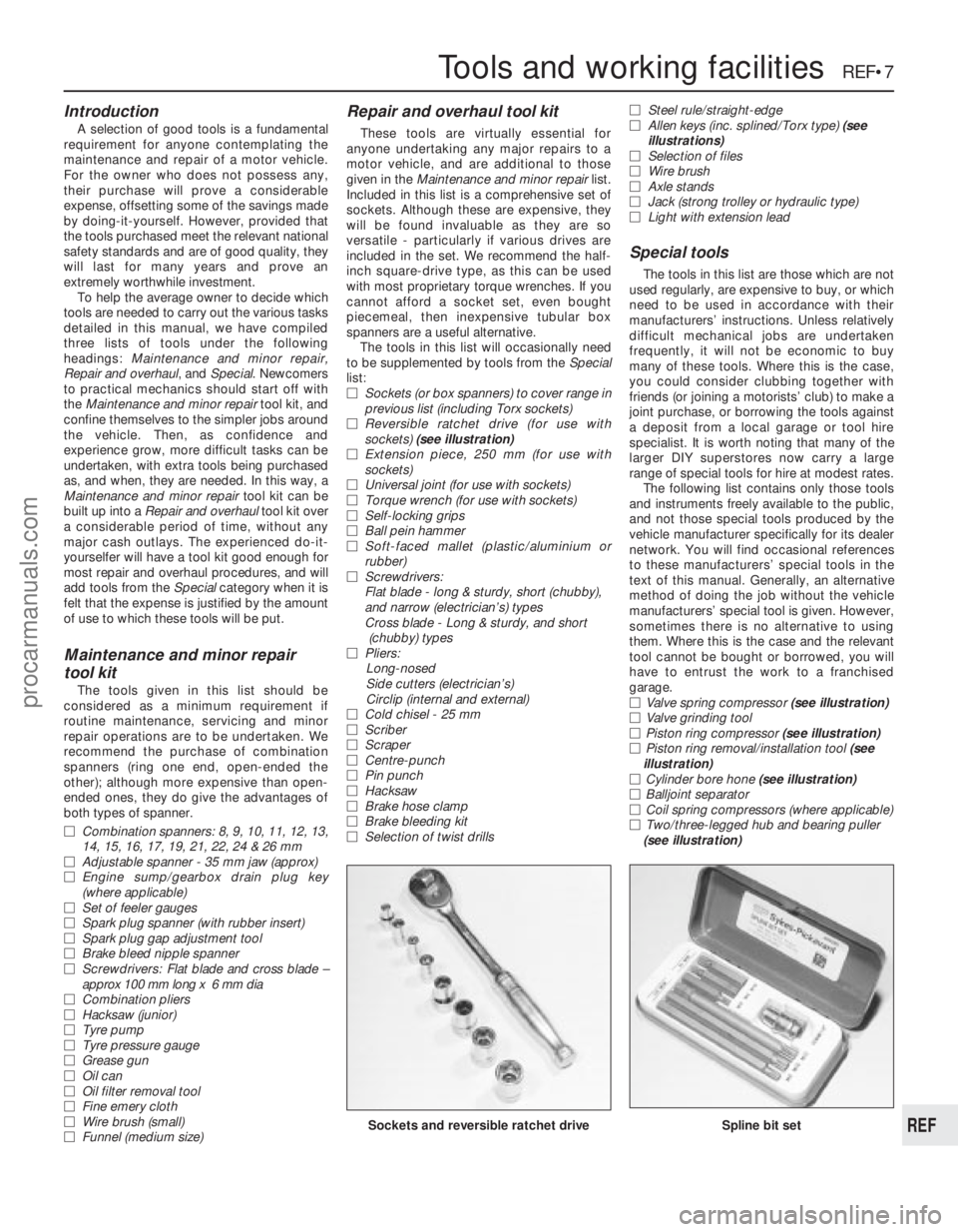
M Reversible ratchet drive (for use with
sockets) (see illustration)
M Extension piece, 250 mm (for use with
sockets)
M Universal joint (for use with sockets)
M Torque wrench (for use with sockets)
M Self-locking grips
M Ball pein hammer
M Soft-faced mallet (plastic/aluminium or
rubber)
M Screwdrivers:
Flat blade - long & sturdy, short (chubby),
and narrow (electrician’s) types
Cross blade - Long & sturdy, and short
(chubby) types
M Pliers:
Long-nosed
Side cutters (electrician’s)
Circlip (internal and external)
M Cold chisel - 25 mm
M Scriber
M Scraper
M Centre-punch
M Pin punch
M Hacksaw
M Brake hose clamp
M Brake bleeding kit
M Selection of twist drills M
Steel rule/straight-edge
M Allen keys (inc. splined/Torx type) (see
illustrations)
M Selection of files
M Wire brush
M Axle stands
M Jack (strong trolley or hydraulic type)
M Light with extension lead
Special tools
The tools in this list are those which are not
used regularly, are expensive to buy, or which
need to be used in accordance with their
manufacturers’ instructions. Unless relatively
difficult mechanical jobs are undertaken
frequently, it will not be economic to buy
many of these tools. Where this is the case,
you could consider clubbing together with
friends (or joining a motorists’ club) to make a
joint purchase, or borrowing the tools against
a deposit from a local garage or tool hire
specialist. It is worth noting that many of the
larger DIY superstores now carry a large
range of special tools for hire at modest rates. The following list contains only those tools
and instruments freely available to the public,
and not those special tools produced by the
vehicle manufacturer specifically for its dealer
network. You will find occasional references
to these manufacturers’ special tools in the
text of this manual. Generally, an alternative
method of doing the job without the vehicle
manufacturers’ special tool is given. However,
sometimes there is no alternative to using
them. Where this is the case and the relevant
tool cannot be bought or borrowed, you will
have to entrust the work to a franchised
garage.
M Valve spring compressor (see illustration)
M Valve grinding tool
M Piston ring compressor (see illustration)
M Piston ring removal/installation tool (see
illustration)
M Cylinder bore hone (see illustration)
M Balljoint separator
M Coil spring compressors (where applicable)
M Two/three-legged hub and bearing puller
(see illustration)
Sockets and reversible ratchet driveSpline bit set
Tools and working facilities REF•7
REF
1595 Ford Fiesta Remakeprocarmanuals.com
http://vnx.su