FORD FIESTA 1989 Service Repair Manual
Manufacturer: FORD, Model Year: 1989, Model line: FIESTA, Model: FORD FIESTA 1989Pages: 296, PDF Size: 10.65 MB
Page 201 of 296
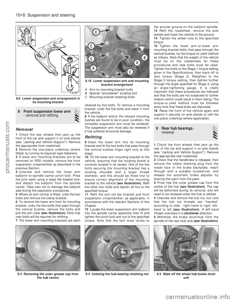
8 Front suspension lower arm- removal and refitting
3
Removal
1Chock the rear wheels then jack up the
front of the car and support it on axle stands
(see “Jacking and Vehicle Support” ). Remove
the appropriate front roadwheel.
2 Remove the one-piece undertray (where
fitted), by turning its bayonet-type fasteners.
3 If lower arm mounting brackets are to be
removed on XR2i models, remove the front
suspension crossmember as described in the
previous Section.
4 Unscrew and remove the lower arm
balljoint-to-spindle carrier pinch-bolt. Prise
the joint open using a large flat-bladed tool,
and detach the balljoint from the spindle
carrier. Take care not to damage the balljoint
seal during the separation procedures.
5 Where an anti-roll bar is fitted, undo the two
bolts and remove the clamp bracket.
6 To remove the lower arm from its mounting
bracket, undo the two bolts that pass through
the vertical bushes, remove the bolts and
pull the arm clear (see illustration). Note that
new bolts will be required for refitting.
7 The lower arm mounting brackets are each retained by five bolts. To remove a mounting
bracket, undo the five bolts and lower it from
the vehicle.
8
If the balljoint and/or the inboard mounting
bushes are found to be in poor condition, the
complete suspension arm must be renewed.
The suspension arm must also be renewed if
it has suffered structural damage.Refitting
9 Insert the lower arm into its mounting
bracket and fit the two bolts that pass through
the vertical bushes finger tight only at this
stage.
10 Fit the lower arm mounting bracket to the
vehicle, ensuring that the locating dowel is
correctly located in its recess. One of the five
bolts securing the mounting bracket has a
locating shoulder and a larger thread
diameter, and this should be fitted first to
ensure correct alignment of the mounting
bracket to the vehicle (see illustration). Refit
the other four bolts and tighten all five to the
specified torque.
11 Refit the anti-roll bar bracket and front
suspension crossmember, as applicable, in
accordance with the relevant Sections of this
Chapter.
12 Locate the lower suspension arm balljoint
into the spindle carrier assembly then fit and
tighten the pinch-bolt and nut to the specified
torque. Note that the bolt must locate to the annular groove on the balljoint spindle.
13
Refit the roadwheel, remove the axle
stands and lower the vehicle to the ground.
14 Tighten the wheel nuts to the specified
torque.
15 Tighten the lower arm-to-lower arm
mounting bracket bolts, that pass through the
vertical bushes, by the torque-to-yield method
as follows. Note that the weight of the vehicle
must be on the roadwheels for these
procedures and new bolts must be used.
Tighten the bolts to the Stage 1 torque setting
given in the Specifications, then back off to
zero torque (Stage 2). Retighten to the
Stage 3 torque setting, then tighten further
through the angle specified for Stage 4, using
an angle-tightening gauge. It is vitally
important that these procedures are followed
and that the bolts are not subjected to further
rotation which could result in them failing. The
torque-to-yield method must be followed
every time that these bolts are disturbed.
16 Raise the front of the vehicle again and
support it securely on axle stands to refit the
one-piece undertray (where applicable).
9 Rear hub bearings -
renewal
3
1 Chock the front wheels then jack up the
rear of the car and support it on axle stands
(see “Jacking and Vehicle Support” ). Remove
the appropriate rear roadwheel.
2 Check that the handbrake is released, then
remove the rubber blanking plug from the
inside face of the brake backplate, reach
through with a suitable screwdriver, and
release the automatic brake adjuster by
levering the catch from the pawl.
3 Prise free the outer grease cap from the
centre of the hub (see illustration). The cap
will be deformed during its removal, and will
need to be renewed when the hub is refitted.
4 Unscrew and remove the hub nut, but note
that the hub nut threads are “handed”
according to side - right-hand to right, left-
hand to left (see illustration) . A left-hand
thread unscrews in a clockwisedirection.
5 Withdraw the brake drum/hub from the
spindle of the rear stub axle (see illustration).
10•8 Suspension and steering
9.5 Slide off the wheel hub/brake drum
unit9.4 Undoing the hub bearing retaining nut9.3 Removing the outer grease cap fromthe hub centre
8.10 Lower suspension arm and mountingbracket arrangement
A Arm-to-mounting bracket bolts
B Special “shouldered” locating bolt
C Mounting bracket retaining bolts
8.6 Lower suspension arm arrangement in its mounting bracket
1595Ford Fiesta Remakeprocarmanuals.com
http://vnx.su
Page 202 of 296
6Use a screwdriver or suitable lever to prise
free the grease retainer (seal) from the hub
bore, but take care not to damage the bore
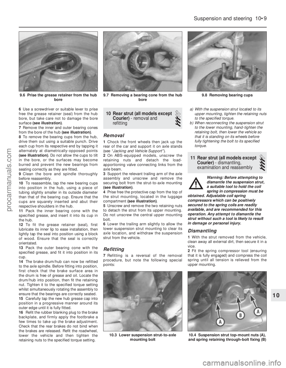
surface (see illustration) .
7 Remove the inner and outer bearing cones
from the bore of the hub (see illustration).
8 To remove the bearing cups from the hub,
drive them out using a suitable punch. Drive
each cup from its respective end by tapping it
alternately at diametrically-opposed points
(see illustration) . Do not allow the cups to tilt
in the bore, or the surfaces may become
burred and prevent the new bearings from
seating correctly as they are fitted.
9 Clean the bore and spindle thoroughly
before reassembly.
10 To reassemble, tap the new bearing cups
into position in the hub, using a piece of
tubing slightly smaller in its outside diameter
than that of the bearing cup. Ensure that the
cups are squarely inserted and abut their
respective shoulders in the hub.
11 Pack the inner bearing cone with the
specified grease, and insert it into its cup in
the hub.
12 To fit the grease retainer (seal), first
lubricate its inner lip to ease installation, then
lightly tap the seal into position using a block
of wood. Ensure that the seal is correctly
orientated.
13 Pack the outer bearing cone with the
specified grease, and fit it into position in its
cup.
14 The brake drum/hub can now be refitted
to the axle spindle. Before fitting into position,
first check that the brake surface area in
the drum is free of grease and oil. Locate the
drum/hub into position, then fit the retaining
nut. Tighten it to the specified torque setting
whilst simultaneously rotating the assembly to
ensure that the bearings are correctly seated.
15 Carefully tap the new hub grease cap into
position in a progressive manner around its
outer edge until it is fully fitted.
16 Refit the rubber blanking plug to the brake
backplate, and firmly apply the footbrake a
few times to take up the brake adjustment.
Check that the rear brakes do not bind when
the brakes are released. Refit the roadwheel,
lower the vehicle and then tighten the
retaining nuts to the specified torque setting.10 Rear strut (all models except Courier) - removal and
refitting
3
Removal
1 Chock the front wheels then jack up the
rear of the car and support it on axle stands
(see “Jacking and Vehicle Support” ).
2 On ABS-equipped models, unscrew the
retaining nuts and detach the load-
apportioning valve connecting links from the
axle beam.
3 Support the relevant trailing arm of the axle
assembly and unscrew and remove the
securing bolt from the strut-to-axle mounting
(see illustration) .
4 Prise free the protective cap from the top of
the strut mounting, located in the luggage
compartment (see illustration) .
5 Unscrew and remove the two retaining nuts
to detach the strut from its upper mounting.
Do not unscrew the central upper mounting
bolt.
6 Lower the trailing arm slightly to allow the
lower suspension strut mounting to clear its
axle location, and withdraw the suspension
strut from the vehicle.
Refitting
7 Refitting is a reversal of the removal
procedure, but note the following special
points: a)
With the suspension strut located to its
upper mounting, tighten the retaining nuts
to the specified torque.
b) When reconnecting the suspension strut
to the lower mounting, hand-tighten the
retaining bolt, then lower the vehicle so
that it is standing on its wheels before
fully tightening the bolt to its specified
torque.
11 Rear strut (all models except
Courier) - dismantling,
examination and reassembly
4
Warning: Before attempting to
dismantle the suspension strut,
a suitable tool to hold the coil
spring in compression must be
obtained. Adjustable coil spring
compressors which can be positively
secured to the spring coils are readily
available, and are recommended for this
operation. Any attempt to dismantle the
strut without such a tool is likely to result
in damage or personal injury.
Dismantling
1 With the strut removed from the vehicle,
clean away all external dirt, then secure it in a
vice.
2 Fit the spring compressor tool (ensuring
that it is fully engaged) and compress the coil
spring until all tension is relieved from the
upper mounting.
Suspension and steering 10•9
9.8 Removing bearing cups9.7 Removing a bearing cone from the hub bore9.6 Prise the grease retainer from the hubbore
10.4 Suspension strut top-mount nuts (A),
and spring retaining through-bolt fixing (B)10.3 Lower suspension strut-to-axle mounting bolt
10
1595Ford Fiesta Remakeprocarmanuals.com
http://vnx.su
Page 203 of 296
3Unscrew and remove the upper mounting
through-bolt and nut.
4 Withdraw the upper mounting cup and the
spring seat.
5 The suspension strut and coil spring can now
be separated. If the coil spring or strut is to be
renewed, the original coil spring must be
released from the compressor. If it is to be re-
used, the coil spring can be left in compression.
Examination
6 With the strut assembly now completely
dismantled, examine the mounting
components for wear, damage or deformation.
Renew any of the components as necessary.
7 Examine the strut for signs of fluid leakage.
Check the strut piston for signs of pitting
along its entire length, and check the strut
body for signs of damage or deterioration of
the mountings. Test the operation of the strut,
holding it in an upright position, by moving the
piston through a full stroke, and then through
short strokes of 50 to 100 mm. In both cases,
the resistance felt should be smooth and
continuous. If the resistance is jerky, or
uneven, or if there is any visible sign of wear
or damage to the strut, renewal is necessary.
Reassembly
8 Reassembly is a reversal of the dismantling
procedure but note the following points: a) When the spring is located over the
suspension strut, the spring seat, cup and
through-bolt fitted, tighten the retaining
bolt to the specified torque.
b) When reassembled, check that the upper
and lower spring tails are correctly
engaged with their spring seats before
removing the spring compressor.
12 Rear axle (all models except
Courier) -
removal and refitting
3
Removal
1 Chock the front wheels then jack up the
rear of the car and support it on axle stands
(see “Jacking and Vehicle Support” ). Remove
the rear roadwheels.
2 Refer to Chapter 9 for details, and disconnect
the handbrake cable equaliser from the primary
cable. Remove the handbrake rear cable from
its adjuster and its fixed body locations.
3 Disconnect the rear brake flexible hydraulic
brake hoses from their rigid line connections.
Clamp the hoses before disconnecting them,
to minimise the fluid loss and air entry into the
hydraulic system (see Chapter 9 for details).
4 On ABS-equipped models, undo the
retaining nuts and detach the ABS load-
apportioning valve operating links from the
axle beam. Do not remove the load-
apportioning valve (see Chapter 9).
5 Locate suitable jacks or axle stands under
the axle beam to support its weight (not to lift
it), then unscrew the four mounting bracket
bolts each side. 6
Unscrew and remove the strut-to-axle
mounting bolt each side.
7 Check that all associated fittings are clear,
then lower the axle and remove it from under
the vehicle.
8 If the twist beam axle has been damaged, it
must be renewed. Refer to Chapter 9 for
details on removing the rear brakes from the
axle. To remove the front mounting/pivot
brackets from the axle, unscrew the pivot bolt.
Refitting
9 Refitting is a reversal of the removal
procedure, but note the following: a) Reconnect the axle at the front floor mountings first, and tighten the retaining
bolts to the specified torque.
b) Reconnect the axle to the suspension struts, but do not fully retighten the securing
bolts until after the vehicle is lowered to the
ground and is standing on its wheels.
c) Ensure that all brake fluid line connections are clean before reconnecting them. Refer
to the appropriate Sections in Chapter 9
for specific details on reconnecting the
brake lines, bleeding the brake hydraulic
system, and for reconnecting the
handbrake cable and its adjustment.
d) When the vehicle is lowered and is standing
on its wheels, tighten the suspension
fastenings to their specified torque settings.
13 Rear axle pivot bushes (all
models except Courier) -
renewal
3
Note: Two different types of pivot bushes
have been fitted during the course of Fiesta
production. It is understood that once stocks
of the early type are exhausted, only the latter
type will be supplied by Ford parts dealers. If
renewing pivot bushes on a pre-April 1990
model, and only the later type bushes are
available, fit the new bushes as described
from paragraph 15 onward.
Pre-April 1990 models
1 Chock the front wheels then jack up the
rear of the car and support it on axle stands
(see “Jacking and Vehicle Support” ).2
Position a suitable support (preferably
adjustable) under the axle twist beam so that
it is capable of carrying the weight of the axle
(not the weight of the vehicle).
3 On ABS-equipped models, undo the
retaining nuts and detach the ABS load-
apportioning valve operating links from the
axle beam. Do not remove the load-
apportioning valve (see Chapter 9).
4 Unscrew the nuts, withdraw the pivot bolts,
then lower the rear axle so that the bushes are
clear of their mounting brackets (see
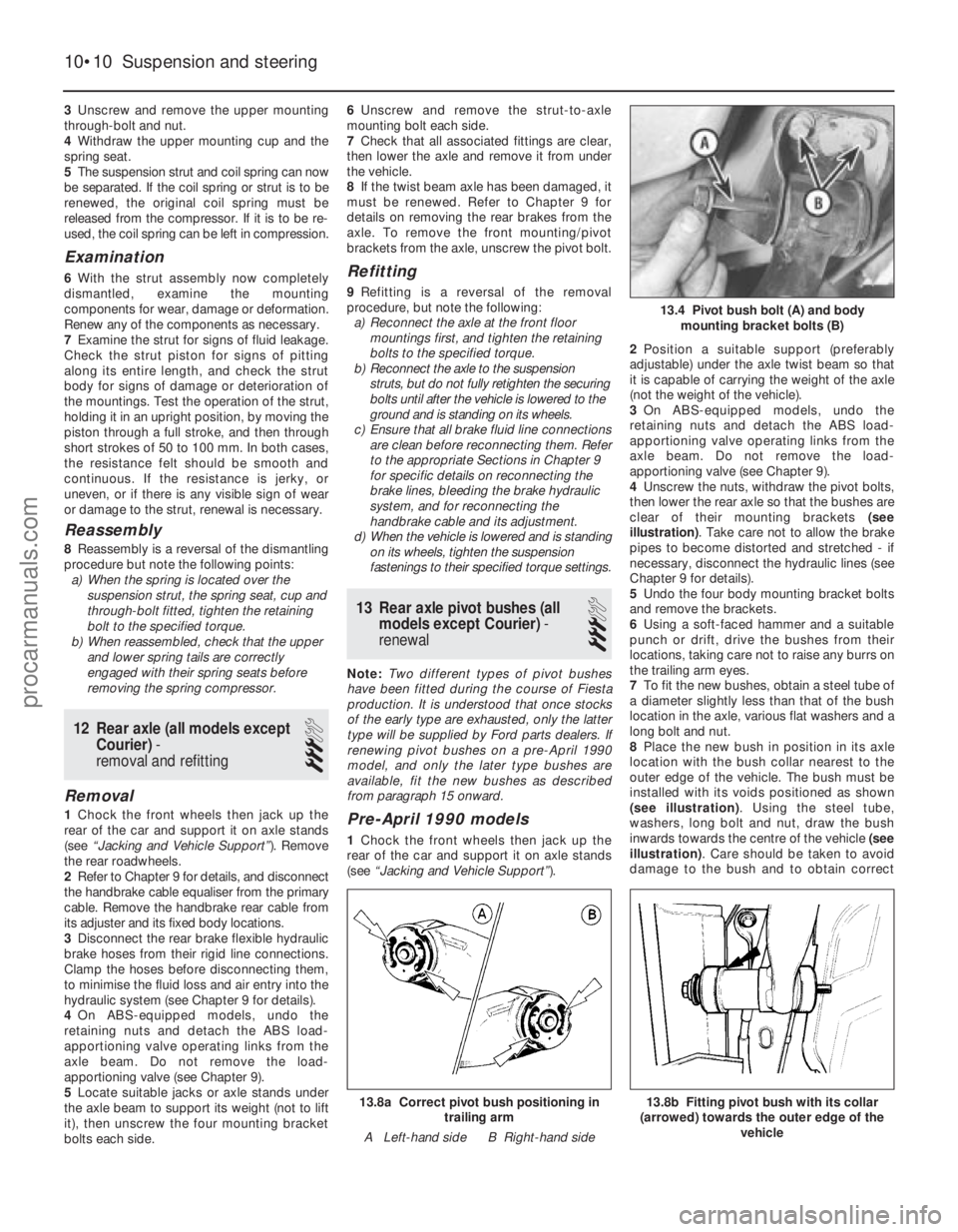
illustration) . Take care not to allow the brake
pipes to become distorted and stretched - if
necessary, disconnect the hydraulic lines (see
Chapter 9 for details).
5 Undo the four body mounting bracket bolts
and remove the brackets.
6 Using a soft-faced hammer and a suitable
punch or drift, drive the bushes from their
locations, taking care not to raise any burrs on
the trailing arm eyes.
7 To fit the new bushes, obtain a steel tube of
a diameter slightly less than that of the bush
location in the axle, various flat washers and a
long bolt and nut.
8 Place the new bush in position in its axle
location with the bush collar nearest to the
outer edge of the vehicle. The bush must be
installed with its voids positioned as shown
(see illustration) . Using the steel tube,
washers, long bolt and nut, draw the bush
inwards towards the centre of the vehicle (see
illustration) . Care should be taken to avoid
damage to the bush and to obtain correct
10•10 Suspension and steering
13.8b Fitting pivot bush with its collar
(arrowed) towards the outer edge of the vehicle13.8a Correct pivot bush positioning intrailing arm
A Left-hand side B Right-hand side
13.4 Pivot bush bolt (A) and body mounting bracket bolts (B)
1595Ford Fiesta Remakeprocarmanuals.com
http://vnx.su
Page 204 of 296
positioning of the voids. Install the bush on
the other side in the same way.
9With the new bushes in position, refit the
body mounting brackets loosely to the trailing
arms - do not fully tighten the pivot bolts at
this stage. Final tightening is carried out with
the vehicle standing on its roadwheels.
10 Raise the axle assembly so that the
conical locating pegs on the body mounting
brackets engage in their body locations. Refit
the body mounting bracket bolts and tighten
to the specified torque.
11 On ABS equipped models, reconnect the
load-apportioning valve operating links to the
rear axle beam
12 If the flexible brake hoses were
disconnected during this operation, reconnect
them and bleed the brake hydraulic system
(see Chapter 9).
13 Lower the vehicle to the ground.
14 Fully tighten the bush pivot bolt nuts to
the specified torque.
April 1990 models onward
15 As mentioned in the note at the start of
this Section, all later models are fitted with
revised bushes which use 12 mm (thread size)
pivot bolts. If the later type bushes are to be
fitted to a pre-April 1990 model, two
corresponding bolts and nuts must be
obtained at the same time, and either the
body mounting brackets must be replaced by
the corresponding modified items, or the
holes in the original brackets must be opened
out (to 12.5 mm) to suit the new bolts.
16 Carry out the operations described in
paragraphs 1 to 4 above.
17 Using a steel tube of suitable diameter,
various flat washers and a long bolt and nut,
draw the bush out of its location in the axle
trailing arm.
18 Clean the bush eye in the trailing arm;
lubricate it, and the new bush, with a soapy
solution (washing-up liquid, for example) prior
to installation.
19 Locate the new bush in position, together
with the steel tube, washers, bolt and nut as
used for removal. Ensure that the bush flange
is positioned on the outside, then draw the
bush fully into position so that its lip is
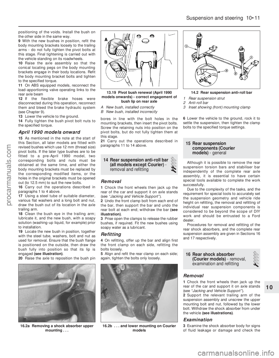
engaged (see illustration) .
20 Raise the axle to reposition the bush pin bores in line with the bolt holes in the
mounting brackets, then insert the pivot bolts.
Screw the retaining nuts into position on the
pivot bolts, but do not fully tighten them at
this stage.
21
Carry out the operations described in
paragraphs 11 to 14 above.
14 Rear suspension anti-roll bar (all models except Courier) -
removal and refitting
2
Removal
1 Chock the front wheels then jack up the
rear of the car and support it on axle stands
(see “Jacking and Vehicle Support” ).
2 Undo the front clamp bolt from each end of
the bar, then support the bar and undo the
rear bolt at each end; withdraw the bar (see
illustration) .
3 Prise open the clamps to release the rubber
bushes, if required. Fit the new bushes using
soapy water as a lubricant.
Refitting
4 On refitting, offer up the bar and align first
the front clamp on each side, refitting the
bolts loosely.
5 Align and refit the rear clamp on each side;
again, tighten the bolts only loosely. 6
Lower the vehicle to the ground, rock it to
settle the suspension, then tighten the clamp
bolts to the specified torque settings.
15 Rear suspension components (Courier
models) - general
Although it is possible to remove the rear
suspension torsion bars and stabiliser bar
independently of the complete rear axle
assembly, it is essential to have certain
special tools available to complete the work
successfully.
Due to the complexity of the tasks, and the
requirement for special tools to accurately set
the suspension geometry and vehicle ride
height on refitting, the removal and refitting of
individual rear suspension components is
considered to be beyond the scope of DIY
work and should be entrusted to a Ford
dealer. Procedures for removal and refitting of the
rear shock absorbers, and the complete rear
suspension assembly are given in Sections 16
and 17 respectively.
16 Rear shock absorber (Courier models) - removal,
examination and refitting
1
Removal
1 Chock the front wheels then jack up the
rear of the car and support it on axle stands
(see “Jacking and Vehicle Support” ).
2 Support the relevant trailing arm of the
suspension assembly and unscrew the upper
mounting bolt and nut, followed by the lower
bolt. Withdraw the shock absorber from under
the vehicle (see illustrations) .
Examination
3Examine the shock absorber body for signs
of fluid leakage or damage and check the
Suspension and steering 10•11
14.2 Rear suspension anti-roll bar
1 Rear suspension strut
2 Anti-roll bar
3 Inset showing (front) mounting clamp13.19 Pivot bush renewal (April 1990
models onwards) - correct engagement of bush lip on rear axle
A New bush, installed correctly
B New bush, installed incorrectly
16.2b . . . and lower mounting on Courier models16.2a Removing a shock absorber uppermounting . . .
10
1595Ford Fiesta Remakeprocarmanuals.com
http://vnx.su
Page 205 of 296
mountings for signs of wear. Test the
operation of the unit, holding it in an upright
position, by moving the piston through a full
stroke, and then through short strokes of 50
to 100 mm. In both cases, the resistance felt
should be smooth and continuous. If the
resistance is jerky, or uneven, or if there is any
visible sign of wear or damage, the shock
absorber should be renewed. Note that if
either unit is to be renewed, it is good practice
to renew both together as a matched pair.
Refitting
4Locate the unit in position and refit the
mounting bolts and nut. Do not fully tighten
the mountings at this stage.
5 Lower the vehicle to the ground and rock it
to settle the suspension. Raise the vehicle
again, as necessary, until the shock absorber
is at an angle of 50° ± 5° to the horizontal.
With the shock absorber in this position,
tighten the upper and lower mountings to the
specified torque.
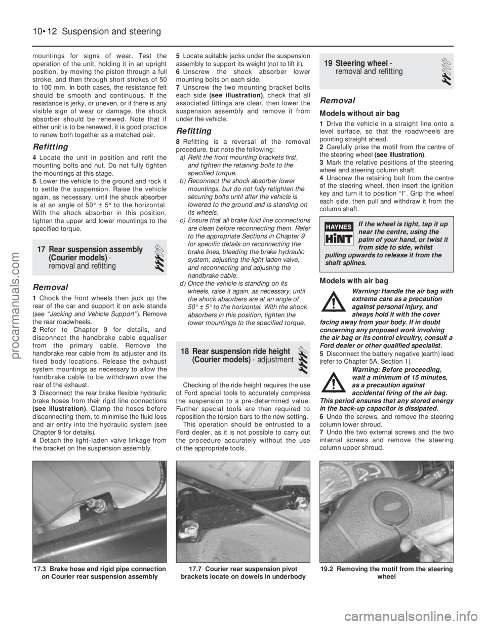
17 Rear suspension assembly (Courier models) -
removal and refitting
3
Removal
1 Chock the front wheels then jack up the
rear of the car and support it on axle stands
(see “Jacking and Vehicle Support” ). Remove
the rear roadwheels.
2 Refer to Chapter 9 for details, and
disconnect the handbrake cable equaliser
from the primary cable. Remove the
handbrake rear cable from its adjuster and its
fixed body locations. Release the exhaust
system mountings as necessary to allow the
handbrake cable to be withdrawn over the
rear of the exhaust.
3 Disconnect the rear brake flexible hydraulic
brake hoses from their rigid line connections
(see illustration) . Clamp the hoses before
disconnecting them, to minimise the fluid loss
and air entry into the hydraulic system (see
Chapter 9 for details).
4 Detach the light-laden valve linkage from
the bracket on the suspension assembly. 5
Locate suitable jacks under the suspension
assembly to support its weight (not to lift it).
6 Unscrew the shock absorber lower
mounting bolts on each side.
7 Unscrew the two mounting bracket bolts
each side (see illustration) , check that all
associated fittings are clear, then lower the
suspension assembly and remove it from
under the vehicle.
Refitting
8 Refitting is a reversal of the removal
procedure, but note the following: a) Refit the front mounting brackets first,
and tighten the retaining bolts to the
specified torque.
b) Reconnect the shock absorber lower
mountings, but do not fully retighten the
securing bolts until after the vehicle is
lowered to the ground and is standing on
its wheels.
c) Ensure that all brake fluid line connections are clean before reconnecting them. Refer
to the appropriate Sections in Chapter 9
for specific details on reconnecting the
brake lines, bleeding the brake hydraulic
system, adjusting the light laden valve,
and reconnecting and adjusting the
handbrake cable.
d) Once the vehicle is standing on its
wheels, raise it again, as necessary, until
the shock absorbers are at an angle of
50° ± 5° to the horizontal. With the shock
absorbers in this position, tighten the
lower mountings to the specified torque.
18 Rear suspension ride height (Courier models) - adjustment
4
Checking of the ride height requires the use
of Ford special tools to accurately compress
the suspension to a pre-determined value.
Further special tools are then required to
reposition the torsion bars to the new setting.
This operation should be entrusted to a
Ford dealer, as it is not possible to carry out
the procedure accurately without the use
of the appropriate tools.
19 Steering wheel -
removal and refitting
2
Removal
Models without air bag
1 Drive the vehicle in a straight line onto a
level surface, so that the roadwheels are
pointing straight ahead.
2 Carefully prise the motif from the centre of
the steering wheel (see illustration).
3 Mark the relative positions of the steering
wheel and steering column shaft.
4 Unscrew the retaining bolt from the centre
of the steering wheel, then insert the ignition
key and turn it to position “I”. Grip the wheel
each side, then pull and withdraw it from the
column shaft.
Models with air bag
Warning: Handle the air bag with
extreme care as a precaution
against personal injury, and
always hold it with the cover
facing away from your body. If in doubt
concerning any proposed work involving
the air bag or its control circuitry, consult a
Ford dealer or other qualified specialist.
5 Disconnect the battery negative (earth) lead
(refer to Chapter 5A, Section 1).
Warning: Before proceeding,
wait a minimum of 15 minutes,
as a precaution against
accidental firing of the air bag.
This period ensures that any stored energy
in the back-up capacitor is dissipated.
6 Undo the screws, and remove the steering
column lower shroud.
7 Undo the two external screws and the two
internal screws and remove the steering
column upper shroud.
10•12 Suspension and steering
19.2 Removing the motif from the steering wheel17.7 Courier rear suspension pivot
brackets locate on dowels in underbody17.3 Brake hose and rigid pipe connection on Courier rear suspension assembly
1595Ford Fiesta Remake
If the wheel is tight, tap it up
near the centre, using the
palm of your hand, or twist it
from side to side, whilst
pulling upwards to release it from the
shaft splines.
procarmanuals.com
http://vnx.su
Page 206 of 296
8Turn the steering wheel as necessary so
that one of the air bag module retaining bolts
becomes accessible from the rear of the
steering wheel. Undo the bolt, then turn
the steering wheel again until the second bolt
is accessible. Undo this bolt also.
9 Withdraw the air bag module from the
steering wheel far enough to access the
wiring multi-plug. Some force may be needed
to free the module from the additional steering
wheel spoke retainers.
10 Disconnect the multi-plug from the rear of
the module, and remove the module from the
vehicle. Warning: Position the air bag
module in a safe place, with the
mechanism facing downwards
as a precaution against
accidental operation.
11 Release the wiring harness from the side
of the steering column and disconnect the air
bag module wiring multi-plug (yellow lead).
12 Where applicable, undo the single screw
and withdraw the Passive Anti-Theft System
(PATS) transceiver from the ignition
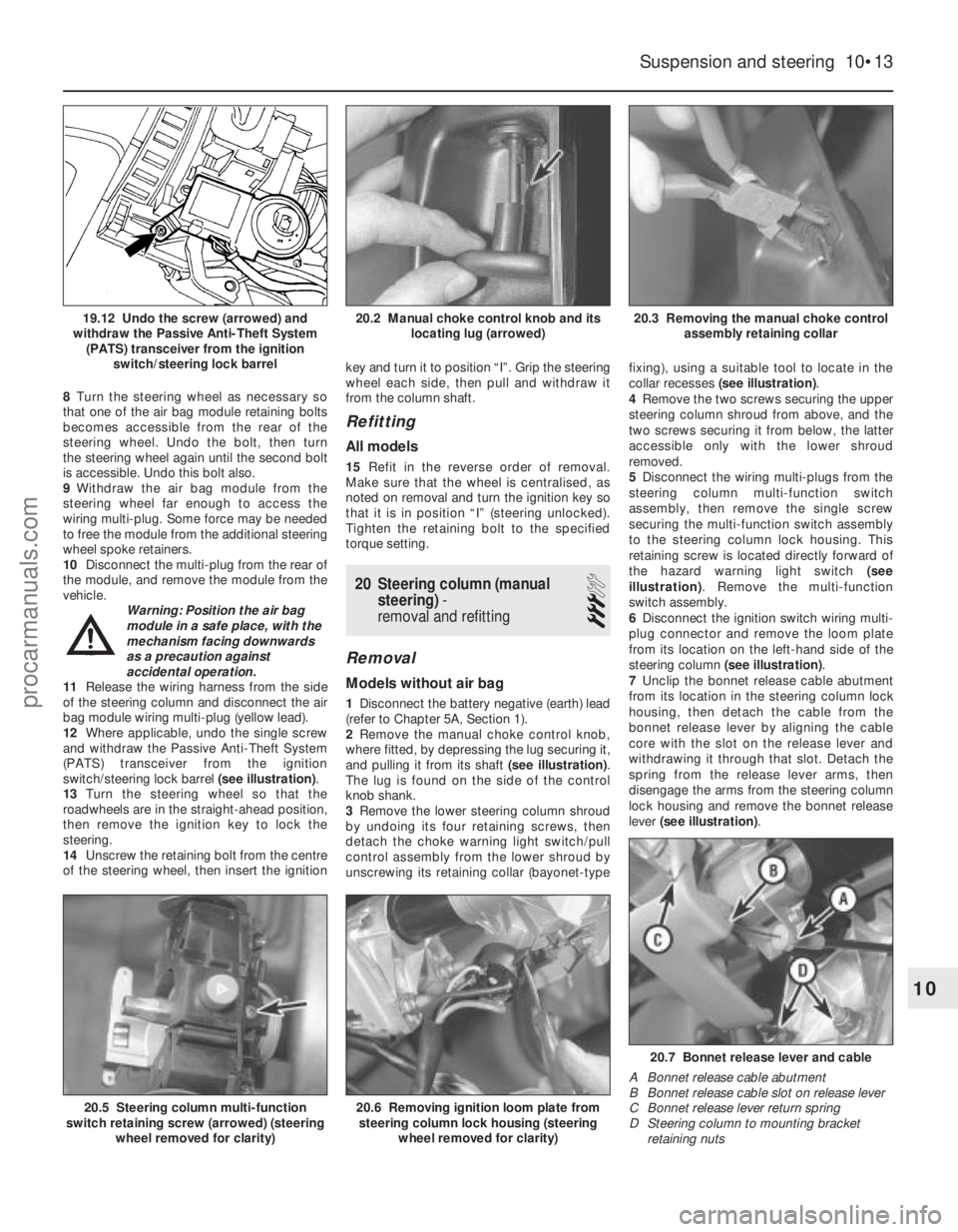
switch/steering lock barrel (see illustration).
13 Turn the steering wheel so that the
roadwheels are in the straight-ahead position,
then remove the ignition key to lock the
steering.
14 Unscrew the retaining bolt from the centre
of the steering wheel, then insert the ignition key and turn it to position “I”. Grip the steering
wheel each side, then pull and withdraw it
from the column shaft.
Refitting
All models
15
Refit in the reverse order of removal.
Make sure that the wheel is centralised, as
noted on removal and turn the ignition key so
that it is in position “I” (steering unlocked).
Tighten the retaining bolt to the specified
torque setting.
20 Steering column (manual steering) -
removal and refitting
3
Removal
Models without air bag
1 Disconnect the battery negative (earth) lead
(refer to Chapter 5A, Section 1).
2 Remove the manual choke control knob,
where fitted, by depressing the lug securing it,
and pulling it from its shaft (see illustration).
The lug is found on the side of the control
knob shank.
3 Remove the lower steering column shroud
by undoing its four retaining screws, then
detach the choke warning light switch/pull
control assembly from the lower shroud by
unscrewing its retaining collar (bayonet-type fixing), using a suitable tool to locate in the
collar recesses
(see illustration) .
4 Remove the two screws securing the upper
steering column shroud from above, and the
two screws securing it from below, the latter
accessible only with the lower shroud
removed.
5 Disconnect the wiring multi-plugs from the
steering column multi-function switch
assembly, then remove the single screw
securing the multi-function switch assembly
to the steering column lock housing. This
retaining screw is located directly forward of
the hazard warning light switch (see
illustration) . Remove the multi-function
switch assembly.
6 Disconnect the ignition switch wiring multi-
plug connector and remove the loom plate
from its location on the left-hand side of the
steering column (see illustration) .
7 Unclip the bonnet release cable abutment
from its location in the steering column lock
housing, then detach the cable from the
bonnet release lever by aligning the cable
core with the slot on the release lever and
withdrawing it through that slot. Detach the
spring from the release lever arms, then
disengage the arms from the steering column
lock housing and remove the bonnet release
lever (see illustration) .
Suspension and steering 10•13
20.3 Removing the manual choke control
assembly retaining collar20.2 Manual choke control knob and its locating lug (arrowed)19.12 Undo the screw (arrowed) and
withdraw the Passive Anti-Theft System (PATS) transceiver from the ignition switch/steering lock barrel
20.7 Bonnet release lever and cable
A Bonnet release cable abutment
B Bonnet release cable slot on release lever
C Bonnet release lever return spring
D Steering column to mounting bracket retaining nuts
20.6 Removing ignition loom plate fromsteering column lock housing (steering
wheel removed for clarity)20.5 Steering column multi-function
switch retaining screw (arrowed) (steering
wheel removed for clarity)
10
1595Ford Fiesta Remakeprocarmanuals.com
http://vnx.su
Page 207 of 296
8Remove the nuts securing the steering
column mounting bracket.
9 Remove the pinch-bolt securing the lower
steering shaft universal joint to the steering
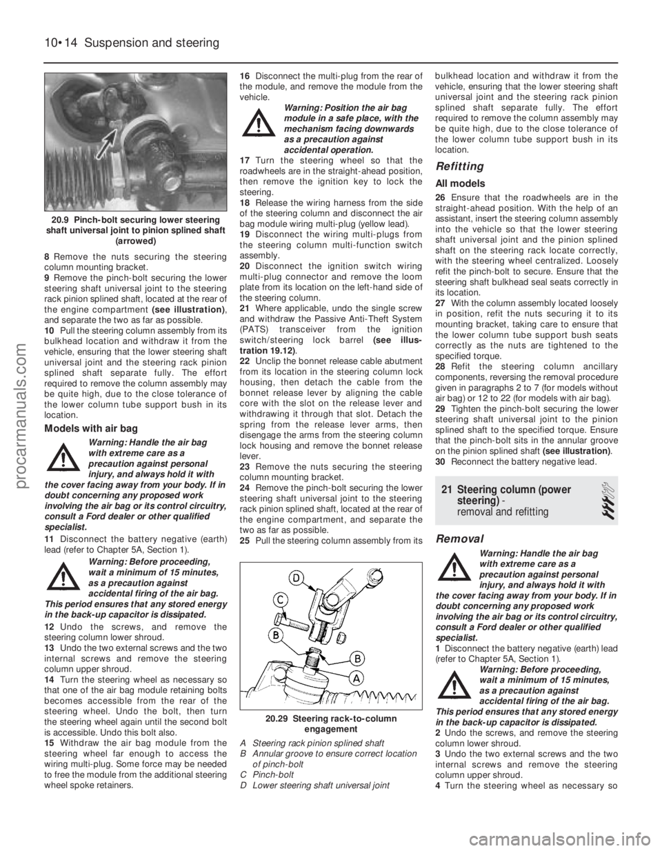
rack pinion splined shaft, located at the rear of
the engine compartment (see illustration),
and separate the two as far as possible.
10 Pull the steering column assembly from its
bulkhead location and withdraw it from the
vehicle, ensuring that the lower steering shaft
universal joint and the steering rack pinion
splined shaft separate fully. The effort
required to remove the column assembly may
be quite high, due to the close tolerance of
the lower column tube support bush in its
location.
Models with air bag
Warning: Handle the air bag
with extreme care as a
precaution against personal
injury, and always hold it with
the cover facing away from your body. If in
doubt concerning any proposed work
involving the air bag or its control circuitry,
consult a Ford dealer or other qualified
specialist.
11 Disconnect the battery negative (earth)
lead (refer to Chapter 5A, Section 1).
Warning: Before proceeding,
wait a minimum of 15 minutes,
as a precaution against
accidental firing of the air bag.
This period ensures that any stored energy
in the back-up capacitor is dissipated.
12 Undo the screws, and remove the
steering column lower shroud.
13 Undo the two external screws and the two
internal screws and remove the steering
column upper shroud.
14 Turn the steering wheel as necessary so
that one of the air bag module retaining bolts
becomes accessible from the rear of the
steering wheel. Undo the bolt, then turn
the steering wheel again until the second bolt
is accessible. Undo this bolt also.
15 Withdraw the air bag module from the
steering wheel far enough to access the
wiring multi-plug. Some force may be needed
to free the module from the additional steering
wheel spoke retainers. 16
Disconnect the multi-plug from the rear of
the module, and remove the module from the
vehicle. Warning: Position the air bag
module in a safe place, with the
mechanism facing downwards
as a precaution against
accidental operation.
17 Turn the steering wheel so that the
roadwheels are in the straight-ahead position,
then remove the ignition key to lock the
steering.
18 Release the wiring harness from the side
of the steering column and disconnect the air
bag module wiring multi-plug (yellow lead).
19 Disconnect the wiring multi-plugs from
the steering column multi-function switch
assembly.
20 Disconnect the ignition switch wiring
multi-plug connector and remove the loom
plate from its location on the left-hand side of
the steering column.
21 Where applicable, undo the single screw
and withdraw the Passive Anti-Theft System
(PATS) transceiver from the ignition
switch/steering lock barrel (see illus-
tration 19.12) .
22 Unclip the bonnet release cable abutment
from its location in the steering column lock
housing, then detach the cable from the
bonnet release lever by aligning the cable
core with the slot on the release lever and
withdrawing it through that slot. Detach the
spring from the release lever arms, then
disengage the arms from the steering column
lock housing and remove the bonnet release
lever.
23 Remove the nuts securing the steering
column mounting bracket.
24 Remove the pinch-bolt securing the lower
steering shaft universal joint to the steering
rack pinion splined shaft, located at the rear of
the engine compartment, and separate the
two as far as possible.
25 Pull the steering column assembly from its bulkhead location and withdraw it from the
vehicle, ensuring that the lower steering shaft
universal joint and the steering rack pinion
splined shaft separate fully. The effort
required to remove the column assembly may
be quite high, due to the close tolerance of
the lower column tube support bush in its
location.
Refitting
All models
26
Ensure that the roadwheels are in the
straight-ahead position. With the help of an
assistant, insert the steering column assembly
into the vehicle so that the lower steering
shaft universal joint and the pinion splined
shaft on the steering rack locate correctly,
with the steering wheel centralized. Loosely
refit the pinch-bolt to secure. Ensure that the
steering shaft bulkhead seal seats correctly in
its location.
27 With the column assembly located loosely
in position, refit the nuts securing it to its
mounting bracket, taking care to ensure that
the lower column tube support bush seats
correctly as the nuts are tightened to the
specified torque.
28 Refit the steering column ancillary
components, reversing the removal procedure
given in paragraphs 2 to 7 (for models without
air bag) or 12 to 22 (for models with air bag).
29 Tighten the pinch-bolt securing the lower
steering shaft universal joint to the pinion
splined shaft to the specified torque. Ensure
that the pinch-bolt sits in the annular groove
on the pinion splined shaft (see illustration).
30 Reconnect the battery negative lead.
21 Steering column (power
steering) -
removal and refitting
3
Removal
Warning: Handle the air bag
with extreme care as a
precaution against personal
injury, and always hold it with
the cover facing away from your body. If in
doubt concerning any proposed work
involving the air bag or its control circuitry,
consult a Ford dealer or other qualified
specialist.
1 Disconnect the battery negative (earth) lead
(refer to Chapter 5A, Section 1). Warning: Before proceeding,
wait a minimum of 15 minutes,
as a precaution against
accidental firing of the air bag.
This period ensures that any stored energy
in the back-up capacitor is dissipated.
2 Undo the screws, and remove the steering
column lower shroud.
3 Undo the two external screws and the two
internal screws and remove the steering
column upper shroud.
4 Turn the steering wheel as necessary so
10•14 Suspension and steering
20.29 Steering rack-to-column
engagement
A Steering rack pinion splined shaft
B Annular groove to ensure correct location of pinch-bolt
C Pinch-bolt
D Lower steering shaft universal joint
20.9 Pinch-bolt securing lower steering
shaft universal joint to pinion splined shaft (arrowed)
1595Ford Fiesta Remakeprocarmanuals.com
http://vnx.su
Page 208 of 296
that one of the air bag module retaining bolts
becomes accessible from the rear of the
steering wheel. Undo the bolt, then turn
the steering wheel again until the second bolt
is accessible. Undo this bolt also.
5Withdraw the air bag module from the
steering wheel far enough to access the
wiring multi-plug. Some force may be needed
to free the module from the additional steering
wheel spoke retainers.
6 Disconnect the multi-plug from the rear of
the module, and remove the module from the
vehicle. Warning: Position the air bag
module in a safe place, with the
mechanism facing downwards
as a precaution against
accidental operation.
7 Turn the steering wheel so that the
roadwheels are in the straight-ahead position,
then remove the ignition key to lock the
steering.
8 Release the wiring harness from the side of
the steering column and disconnect the air
bag module wiring multi-plug (yellow lead).
9 Disconnect the wiring multi-plugs from the
steering column multi-function switch
assembly.
10 Disconnect the ignition switch wiring
multi-plug connector and remove the loom
plate from its location on the left-hand side of
the steering column.
11 Undo the single screw and withdraw the
Passive Anti-Theft System (PATS) transceiver
from the ignition switch/steering lock barrel
(see illustration 19.12) .
12 Unclip the bonnet release cable abutment
from its location in the steering column lock
housing, then detach the cable from the
bonnet release lever by aligning the cable
core with the slot on the release lever and
withdrawing it through that slot. Detach the
spring from the release lever arms, then
disengage the arms from the steering column
lock housing and remove the bonnet release
lever.
13 Remove the C-clip at the base of the
steering column shaft, below the universal
joint.
14 Remove the nuts securing the steering
column mounting bracket.
15 Pull the steering column assembly from its
bulkhead location and withdraw it from the
vehicle, ensuring that the steering column
shaft and flexible coupling separate fully.
Refitting
16 Ensure that the roadwheels are in the
straight-ahead position and the steering
column is locked. With the help of an
assistant, insert the steering column assembly
into the vehicle so that the steering column
shaft engages with the flexible coupling.
17 Refit the steering column shaft C-clip.
18 With the column assembly located loosely
in position, refit and tighten the nuts securing
it to its mounting bracket.
19 Refit the steering column ancillary components, reversing the removal procedure
given in paragraphs 2 to 12.
20
Reconnect the battery negative lead.
22 Steering gear rubber gaiters
- renewal
3
1Remove the track rod end balljoint as
described in Section 28.
2 Remove the one-piece undertray where
fitted, by turning its bayonet-type fasteners,
and on XR2i models, remove the front
suspension crossmember as described in
Section 7.
3 Count the number of exposed threads
visible, from the end of the track rod to the
track rod end balljoint locknut, and record this
figure. Now unscrew the locknut from the
track rod.
4 Release the clip(s), and slide the gaiter off
the rack-and-pinion housing and track rod.
5 Scrape off all grease from the old gaiter,
and apply to the track rod inner joint. Wipe
clean the seating areas on the rack-and-
pinion housing and track rod.
6 Slide the new gaiter onto the housing and
track rod, and secure with the retaining clips.
Ensure that the narrow neck locates correctly
in the track rod groove.
7 Screw the track rod end balljoint locknut
back onto the track rod until the same number
of threads, as counted on removal, are visible.
8 Refit the track rod end balljoint as
described in Section 28.
9 Refit the front suspension crossmember
and one-piece undertray, as applicable.
23 Steering gear (manual steering) -
removal and refitting
3
Removal
1 Disconnect the battery negative (earth) lead
(refer to Chapter 5A, Section 1).
2 Chock the rear wheels then jack up the
front of the car and support it on axle stands
(see “Jacking and Vehicle Support” ). Remove
the front roadwheels.
3 Remove the one-piece undertray where
fitted, by turning its bayonet-type fasteners,
and on XR2i models, remove the front
suspension crossmember as described in
Section 7.
4 Remove the pinch-bolt securing the pinion
splined shaft to the lower steering shaft
universal joints, located at the rear of the
engine compartment.
5 Separate the track rod end balljoints from
the steering arms, as described in Section 28.
6 Remove the lower brake servo support
bracket bolt.
7 Remove the other bolt securing the steering
rack assembly to the bulkhead, then withdraw
it from the right-hand side of the vehicle, taking care to disengage the pinion splined
shaft from the lower steering shaft universal
joint as the assembly is moved.
Refitting
8
Centralize the rack and steering wheel, then
engage the pinion splined shaft to the lower
steering shaft universal joint.
9 Refit the steering rack assembly mounting
bolts to the bulkhead and tighten to the
specified torque, ensuring that the servo
support bracket is correctly held.
10 Refit the pinion splined shaft-to-lower
steering shaft universal joint pinch-bolt and
nut and tighten to the specified torque,
ensuring that the pinch-bolt locates to the
annular groove as the pinion splined shaft.
11 Refit the track rod end balljoints to the
steering arms, as detailed in Section 28. As
long as the track rod end-to-track rod relative
positions have not been disturbed, it will not
be necessary to reset the front wheel
alignment.
12 Refit the front suspension crossmember
and one-piece undertray, as applicable.
13 Refit the roadwheels, then lower the
vehicle to the ground. Tighten the roadwheel
nuts to the specified torque with the vehicle
on its wheels.
24 Steering gear (power steering) -
removal and refitting
4
Removal
1 Disconnect the battery negative (earth) lead
(refer to Chapter 5A, Section 1).
2 Chock the rear wheels then jack up the
front of the car and support it on axle stands
(see “Jacking and Vehicle Support” ). Remove
the front roadwheels.
3 Remove the one-piece undertray where
fitted, by turning its bayonet-type fasteners,
and on XR2i models, remove the front
suspension crossmember as described in
Section 7.
4 Remove the pinch-bolt securing the pinion
splined shaft to the lower steering shaft
flexible coupling, located at the rear of the
engine compartment.
5 Undo the retaining screws, and detach the
clips securing the power steering hydraulic
pressure pipes to the steering gear.
6 Position a suitable container under the
hydraulic pipe connections to the steering
gear. Unscrew the pipe unions, then detach
the pipes from the valve body. Withdraw the
pipes from the steering gear, and drain the
hydraulic fluid into the container.
7 Plug the exposed ends of the hydraulic line
connections, to prevent the ingress of dirt and
further fluid loss. Note that new O-ring seals
will be needed for the pressure and return
hose connections when reconnecting.
8 Slacken the upper bolts securing the
steering gear support brackets. On left-hand
Suspension and steering 10•15
10
1595Ford Fiesta Remakeprocarmanuals.com
http://vnx.su
Page 209 of 296
drive models, remove the brace from the stud
on the left-hand side of the steering gear.
9Undo the two bolts securing the support
brackets to the steering gear and move the
brackets and swing the brackets clear.
10 Unhook the steering gear from the
apertures in the bulkhead and remove the
assembly from the right-hand wheel arch.
Ensure that the pressure check valve does not
fall out of the pressure port in the valve body
as the steering gear is removed.
Refitting
11 Centralize the steering gear and steering
wheel, then engage the pinion splined shaft to
the lower steering shaft flexible coupling.
12 Hook the steering gear into the apertures
in the bulkhead then align the support
brackets and refit the two bolts. Tighten the
support bracket upper bolts and support
bracket-to-steering gear bolts to the specified
torque.
13 On left-hand drive models, refit the brace
to the stud on the left-hand side of the
steering gear.
14 Fit new O-ring seals to the pressure and
return hoses, then reconnect the hydraulic
lines to the steering gear. Secure the pipes
with the retaining clips.
15 Refit the pinion splined shaft-to-lower
steering shaft flexible coupling pinch-bolt and
nut and tighten to the specified torque.
16 Refit the track rod end balljoints to the
steering arms, as detailed in Section 28. As
long as the track rod end-to-track rod relative
positions have not been disturbed, it will not
be necessary to reset the front wheel
alignment.
17 Refit the front suspension crossmember
and one-piece undertray, as applicable.
18 Refit the roadwheels, then lower the
vehicle to the ground. Tighten the roadwheel
nuts with the vehicle on its wheels to the
specified torque.
19 On completion, bleed the power steering
hydraulic system as described in Section 27.
Check for any signs of fluid leakage from the
system hoses and connections.
25 Power steering pump -
removal and refitting
4
Removal
HCS engine models
1 Disconnect the battery negative (earth) lead
(refer to Chapter 5A, Section 1).
2 Chock the rear wheels then jack up the
front of the car and support it on axle stands
(see “Jacking and Vehicle Support” ). Remove
the front roadwheel.
3 Remove the auxiliary drivebelt as described
in Chapter 1.
4 Insert a 9 mm Allen key into the centre of
the pump drive spindle to prevent it from turning, then unscrew and remove the three
pump pulley retaining bolts. Withdraw the
pulley from the pump.
5
Position a suitable container beneath the
power steering pump, then unscrew and detach
the fluid high pressure pipe and fluid return
hose from the pump. As they are detached from
the pump, allow the fluid to drain from the pipe
and hose (and the pump) into the container.
Plug the exposed ends of the pipe, hose and
the pump connections, to prevent the ingress of
dirt and excessive fluid loss.
6 Unscrew the four retaining bolts (three from
the front and one from the rear) and withdraw
the pump from the vehicle.
PTE engine models
7 Disconnect the battery negative (earth) lead
(refer to Chapter 5A, Section 1).
8 Refer to the relevant Part of Chapter 4 and
remove the air cleaner assembly and air inlet
components as necessary for access to the
pump.
9 Chock the rear wheels then jack up the
front of the car and support it on axle stands
(see “Jacking and Vehicle Support” ). Remove
the front roadwheel.
10 Refer to Chapter 1 and drain the cooling
system.
11 Refer to Chapter 1 and remove the
auxiliary drivebelt.
12 Insert a 9 mm Allen key into the centre of
the pump drive spindle to prevent it from
turning, then unscrew and remove the three
pump pulley retaining bolts. Refit the
roadwheel, lower the vehicle and withdraw the
pump pulley from above.
13 Disconnect the cooling system hoses as
necessary to gain access to the power
steering pump.
14 Disconnect the pressure switch multi-plug
from the pressure switch located in the fluid
high pressure pipe.
15 Position a suitable container beneath the
power steering pump, then disconnect the
high pressure pipe at the union located part
way along the pipe. Allow the fluid to drain
from the pipe into the container.
16 Disconnect the high pressure pipe clamp
bracket and the fluid return hose from the
pump. Allow the fluid to drain into the
container then plug the exposed ends of the
pipe, hose and the pump connections, to
prevent the ingress of dirt and excessive fluid
loss.
17 Unscrew the pump mounting bolt located
at the rear of the pump and remove the pipe
clamp bracket.
18 Unscrew the three pump mounting bolts
located at the front of the pump and remove
the pump, complete with high pressure pipe,
from the vehicle.
19 If required, the high pressure pipe can be
removed from the pump after unscrewing the
union nut.
Zetec engine models
Note: For this operation, the engine will need
to be supported from above to allow removal of the right-hand engine mounting, and also to
allow the vehicle to be raised for work
underneath, and lowered for work from above.
A proprietary engine support bar (or home-
made alternative) fitted in the front wing drain
channel each side is ideal for this purpose, but
care must be taken not to damage the wings
or their paintwork.
20
Disconnect the battery negative (earth)
lead (refer to Chapter 5A, Section 1).
21 Suitably support the right-hand side of the
engine (see the note at the beginning of this
sub-Section) so that all the load is removed
from the engine mounting.
22 Remove the right-hand engine mounting
as described in Chapter 2C.
23 Refer to Chapter 1 and drain the cooling
system.
24 Chock the rear wheels then jack up the
front of the car and support it on axle stands
(see “Jacking and Vehicle Support” ). Remove
the front roadwheel.
25 Undo the retaining screws, and remove
the drivebelt lower guard from the underbody.
26 Refer to Chapter 11 and remove the wheel
arch liner.
27 Refer to Chapter 1 and remove the
auxiliary drivebelt.
28 Insert a 9 mm Allen key into the centre of
the pump drive spindle to prevent it from
turning, then unscrew and remove the three
pump pulley retaining bolts. Refit the
roadwheel, lower the vehicle and withdraw the
pump pulley from above.
29 Refer to Chapter 12 and remove the right-
hand headlight unit.
30 Refit the roadwheel and lower the vehicle
to the ground.
31 Position a suitable container beneath the
power steering fluid reservoir, then disconnect
the fluid return hose from the reservoir. Allow
the fluid to drain from the hose and reservoir
into the container.
32 Plug the exposed ends of the hose and
the reservoir, to prevent the ingress of dirt and
excessive fluid loss.
33 Remove the high pressure pipe clamp
brackets from the engine then disconnect the
high pressure pipe at the union located over
the camshaft cover. Place absorbent rags
under the union as it is disconnected to
collect any escaping fluid. Plug the
disconnected pipe ends to prevent the
ingress of dirt and excessive fluid loss.
34 Disconnect the cooling system hoses as
necessary to gain access to the power
steering pump.
35 Unscrew the two pump mounting bolts
located at the rear of the pump.
36 Unscrew the two pump mounting bolts
located at the front of the pump and remove
the pump, complete with high pressure pipe
and fluid return hose, upwards and out of the
engine compartment.
37 If required, the high pressure pipe and
fluid return hose can be removed from the
pump after unscrewing the union nut or
slackening the hose clip as applicable.
10•16 Suspension and steering
1595Ford Fiesta Remakeprocarmanuals.com
http://vnx.su
Page 210 of 296
Refitting
All models
38Refitting is a reversal of removal, bearing
in mind the following points:
a) Tighten all nuts and bolts to the specified torque. Remove the plugs from the
disconnected pipes, hoses and unions
and ensure that the pipes are located
correctly so that they do not foul any
surrounding components.
b) Refit the auxiliary drivebelt as described in
Chapter 1.
c) Where drained, refill the cooling system as described in Chapter 1.
d) Refit or reconnect any additional
components removed for access as
described in the relevant Sections and
Chapters of this manual.
e) On completion, bleed the power steering
hydraulic system as described in Section
27. Check for any signs of fluid leakage
from the system hoses and connections.
26 Power steering fluid cooler -
removal and refitting
2
Removal
1 Disconnect the battery negative (earth) lead
(refer to Chapter 5A, Section 1).
2 Position a suitable container beneath the
power steering fluid cooler hose connections,
then disconnect the hoses at the quick-fit
couplings on the fluid cooler. Allow the fluid to
drain from the hose and reservoir into the
container.
3 Plug the exposed ends of the hose and the
reservoir, to prevent the ingress of dirt and
excessive fluid loss.
4 Refer to Chapter 11 and remove the bonnet
lock assembly and the front bumper.
5 Undo the bolts securing the cooler side
support bracket and the bonnet lock stay, and
remove the fluid cooler and bonnet lock stay
as an assembly.
6 Undo the two bolts and remove the stay
from the fluid cooler.
Refitting
7 Refitting is a reversal of removal. On
completion, bleed the power steering
hydraulic system as described in Section 27.
27 Power steering hydraulic system - bleeding
2
1Following any operation in which the power
steering fluid lines have been disconnected,
the power steering system must be bled to
remove any trapped air.
2 With the front wheel in the straight-ahead
position, check the power steering fluid level
in the reservoir and, if low, top-up with fresh fluid to the “MAX” or “MAX COLD” level mark.
Pour the fluid slowly to prevent air bubbles
forming, and use only the specified fluid (refer
to
“Lubricants, fluids and tyre pressures” ).
3 Start the engine and allow it to idle. Check
the hoses and connections for leaks.
4 Stop the engine and recheck the fluid level.
Add more, if necessary, up to the “MAX” or
“MAX COLD” level mark.
5 Start the engine again, allow it to idle, then
bleed the system by slowly moving the
steering from lock-to-lock several times. This
should purge the system of all internal air.
However, if air remains in the system
(indicated by the steering operation being very
noisy), leave the vehicle overnight and repeat
the procedure again the next day.
6 If air still remains in the system, it may be
necessary to resort to the Ford method of
bleeding, which uses a vacuum pump and a
modified reservoir filler cap to which the pump
can be connected. Turn the steering to the
right until it is near the stop, then fit the
vacuum pump to the fluid reservoir, and apply
0.51 bars of vacuum. Maintain the vacuum for
a minimum of 5 minutes, then repeat
the procedure with the steering turned to the
left.
7 Keep the fluid level topped-up throughout
the bleeding procedure; note that the fluid
temperature increases, the level will rise.
8 On completion, switch the engine off, and
return the wheels to the straight-ahead
position.
28 Track rod end balljoint -
removal and refitting
2
Removal
1 Chock the rear wheels then jack up the
front of the car and support it on axle stands
(see “Jacking and Vehicle Support” ). Remove
the appropriate front roadwheel.
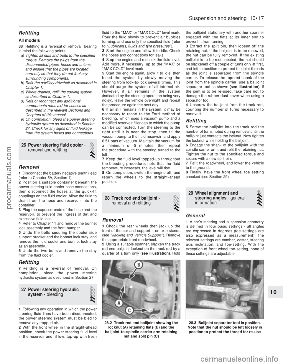
2 Using a suitable spanner, slacken the track
rod end balljoint locknut on the track rod by a
quarter of a turn only (see illustration). Holdthe balljoint stationary with another spanner
engaged with the flats at its inner end to
prevent it from turning.
3
Extract the split pin, then loosen off the
retaining nut. If the balljoint is to be renewed,
the nut can be fully removed. If the existing
balljoint is to be reconnected, the nut should
be slackened off a couple of turns only at first,
and left in position to protect the joint threads
as the joint is separated from the spindle
carrier. To release the tapered shank of the
joint from the spindle carrier, use a balljoint
separator tool as shown (see illustration). If
the joint is to be re-used, take care not to
damage the rubber dust cover when using a
separator tool.
4 Unscrew the balljoint from the track rod,
counting the number of turns necessary to
remove it.
Refitting
5 Screw the balljoint into the track rod the
number of turns noted during removal until the
balljoint just contacts the locknut. Now tighten
the locknut while holding the balljoint.
6 Engage the shank of the balljoint with the
spindle carrier arm, and refit the retaining nut.
Tighten the nut to the specified torque and
secure with a new split pin.
7 Refit the roadwheel, and lower the vehicle
to the ground.
8 Finally, have the front wheel toe setting
checked (see Section 29).
29 Wheel alignment and steering angles - general
information
4
General
1 A car’s steering and suspension geometry
is defined in four basic settings - all angles
are expressed in degrees (toe settings are
also expressed as a measurement); the
relevant settings are camber, castor, steering
axis inclination, and toe-setting. With the
exception of front wheel toe-setting, none of
these settings are adjustable.
Suspension and steering 10•17
28.3 Balljoint separator tool in position.
Note that the nut should be left loosely in position to protect the thread for re-use28.2 Track rod end balljoint showing the locknut (A) retaining flats (B) and the
balljoint-to-spindle carrier arm retaining
nut and split pin (C)
10
1595Ford Fiesta Remakeprocarmanuals.com
http://vnx.su