drain bolt FORD FIESTA 1989 Service Owner's Manual
[x] Cancel search | Manufacturer: FORD, Model Year: 1989, Model line: FIESTA, Model: FORD FIESTA 1989Pages: 296, PDF Size: 10.65 MB
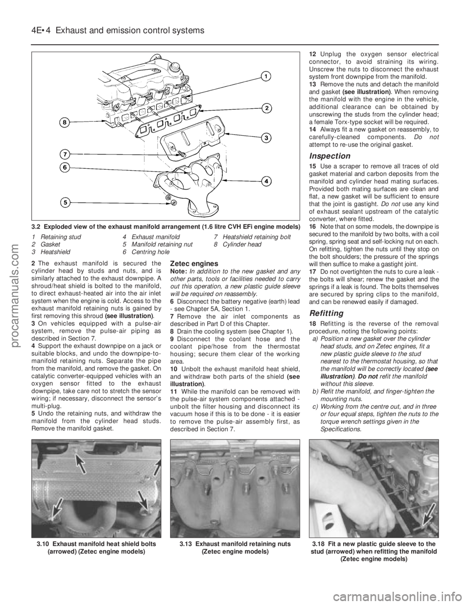
Page 111 of 296
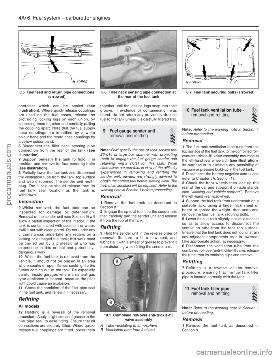
container which can be sealed (see
illustration) . Where quick-release couplings
are used on the fuel hoses, release the
protruding locking lugs on each union, by
squeezing them together and carefully pulling
the coupling apart. Note that the fuel supply
hose couplings are identified by a white
colour band and the return hose couplings by
a yellow colour band.
6 Disconnect the filler neck sensing pipe
connection from the rear of the tank (see
illustration) .
7 Support beneath the tank to hold it in
position and remove its four securing bolts
(see illustration) .
8 Partially lower the fuel tank and disconnect
the ventilation tube from the tank top surface
and also disconnect the sender unit multi-
plug. The filler pipe should release from its
fuel tank seal location as the tank is
withdrawn.
Inspection
9 Whilst removed, the fuel tank can be
inspected for damage or deterioration.
Removal of the sender unit (see Section 9) will
allow a partial inspection of the interior. If the
tank is contaminated with sediment or water,
swill it out with clean petrol. Do not under any
circumstances undertake any repairs on a
leaking or damaged fuel tank; this work must
be carried out by a professional who has
experience in this critical and potentially-
dangerous work.
10 Whilst the fuel tank is removed from the
vehicle, it should not be placed in an area
where sparks or open flames could ignite the
fumes coming out of the tank. Be especially
careful inside garages where a natural-gas
type appliance is located, because the pilot
light could cause an explosion.
11 Check the condition of the filler pipe seal
in the fuel tank, and renew it if necessary.
Refitting
All models
12 Refitting is a reversal of the removal
procedure. Apply a light smear of grease to the
filler pipe seal, to ease fitting. Ensure that all
connections are securely fitted. Where quick-
release fuel couplings are fitted, press them together until the locking lugs snap into their
groove. If evidence of contamination was
found, do not return any previously-drained
fuel to the tank unless it is carefully filtered first.
9
Fuel gauge sender unit -
removal and refitting
3
Note: Ford specify the use of their service tool
23-014 (a large box spanner with projecting
teeth to engage the fuel gauge sender unit
retaining ring’s slots) for this task. While
alternatives are possible, in view of the difficulty
experienced in removing and refitting the
sender unit, owners are strongly advised to
obtain the correct tool before starting work. The
help of an assistant will be required. Refer to the
warning note in Section 1 before proceeding.
Removal
1 Remove the fuel tank as described in
Section 8.
2 Engage the special tool into the sender unit
then carefully turn the sender unit and release
it from the top of the tank.
Refitting
3 Refit the sender unit in the reverse order of
removal. Be sure to fit a new seal, and
lubricate it with a smear of grease to prevent it
from distorting when fitting the sender unit.
10 Fuel tank ventilation tube -
removal and refitting
3
Note: Refer to the warning note in Section 1
before proceeding.
Removal
1 The fuel tank ventilation tube runs from the
top surface of the fuel tank to the combined roll-
over/anti-trickle-fill valve assembly mounted in
the left-hand rear wheelarch (see illustration).
Its purpose is to eliminate any possibility of
vacuum or pressure build-up in the fuel tank.
2 Disconnect the battery negative (earth) lead
(refer to Chapter 5A, Section 1).
3 Chock the front wheels then jack up the
rear of the car and support it on axle stands
(see “Jacking and vehicle support” ). Remove
the left-hand rear roadwheel.
4 Support the fuel tank from underneath on a
suitable jack, using a large thick sheet of
board to spread the weight, then undo and
remove the four fuel tank securing bolts.
5 Lower the fuel tank slightly in such a manner
so as to allow access to disconnect the
ventilation tube from the tank top surface.
Ensure that the fuel tank does not foul or strain
any adjacent components as it is lowered;
take appropriate action, as necessary.
6 Disconnect the ventilation tube from the
combined roll-over/anti-trickle-fill valve, release
the tube from its retaining clips and remove.
Refitting
7 Refitting is a reversal of the removal
procedure, ensuring that the fuel tank filler
pipe is located correctly with the tank.
11 Fuel tank filler pipe -
removal and refitting
3
Note: Refer to the warning note in Section 1
before proceeding.
Removal
1 Remove the fuel tank as described in
Section 8.
4A•6 Fuel system – carburettor engines
10.1 Combined roll-over anti-trickle-fill valve assembly
A Tube ventilating to atmosphere
B Ventilation tube from fuel tank
8.7 Fuel tank securing bolts (arrowed)8.6 Filler neck sensing pipe connection at the rear of the fuel tank
1595Ford Fiesta Remake
8.5 Fuel feed and return pipe connections
(arrowed)procarmanuals.com
http://vnx.su
Page 123 of 296
As it is detached, plug the end of the hose to
prevent excessive fuel spillage and the ingress
of dirt. Where a crimped type hose clip is fitted,
cut it free, taking care not to damage the hose;
a new screw type clip will need to be obtained
to replace the crimped clip during reassembly.
7Disconnect the relevant vacuum pipes from
the carburettor. As they are detached, label
them to ensure correct reassembly.
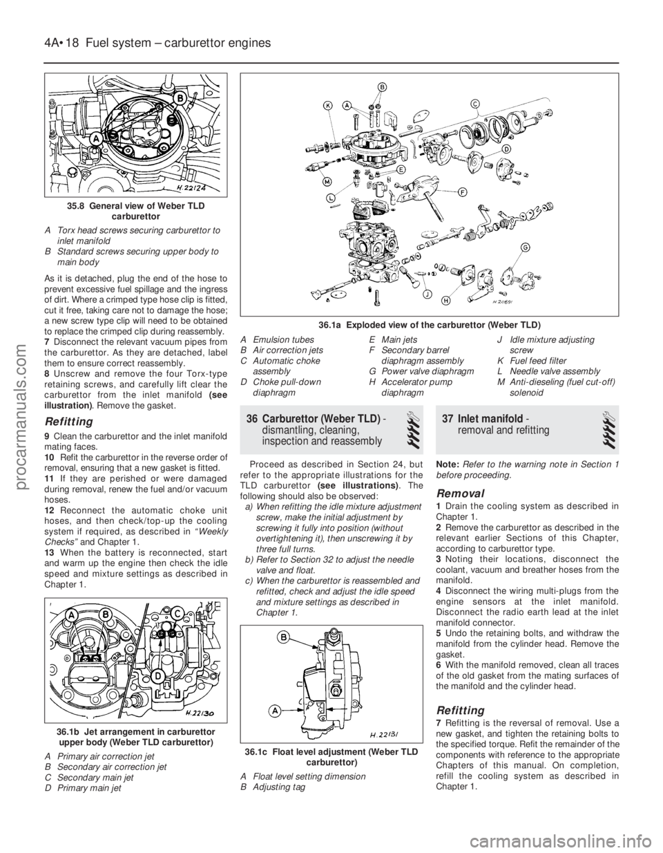
8 Unscrew and remove the four Torx-type
retaining screws, and carefully lift clear the
carburettor from the inlet manifold (see
illustration) . Remove the gasket.
Refitting
9Clean the carburettor and the inlet manifold
mating faces.
10 Refit the carburettor in the reverse order of
removal, ensuring that a new gasket is fitted.
11 If they are perished or were damaged
during removal, renew the fuel and/or vacuum
hoses.
12 Reconnect the automatic choke unit
hoses, and then check/top-up the cooling
system if required, as described in “Weekly
Checks” and Chapter 1.
13 When the battery is reconnected, start
and warm up the engine then check the idle
speed and mixture settings as described in
Chapter 1.
36 Carburettor (Weber TLD) -
dismantling, cleaning,
inspection and reassembly
4
Proceed as described in Section 24, but
refer to the appropriate illustrations for the
TLD carburettor (see illustrations) . The
following should also be observed: a) When refitting the idle mixture adjustment
screw, make the initial adjustment by
screwing it fully into position (without
overtightening it), then unscrewing it by
three full turns.
b) Refer to Section 32 to adjust the needle
valve and float.
c) When the carburettor is reassembled and refitted, check and adjust the idle speed
and mixture settings as described in
Chapter 1.
37 Inlet manifold -
removal and refitting
4
Note: Refer to the warning note in Section 1
before proceeding.
Removal
1 Drain the cooling system as described in
Chapter 1.
2 Remove the carburettor as described in the
relevant earlier Sections of this Chapter,
according to carburettor type.
3 Noting their locations, disconnect the
coolant, vacuum and breather hoses from the
manifold.
4 Disconnect the wiring multi-plugs from the
engine sensors at the inlet manifold.
Disconnect the radio earth lead at the inlet
manifold connector.
5 Undo the retaining bolts, and withdraw the
manifold from the cylinder head. Remove the
gasket.
6 With the manifold removed, clean all traces
of the old gasket from the mating surfaces of
the manifold and the cylinder head.
Refitting
7 Refitting is the reversal of removal. Use a
new gasket, and tighten the retaining bolts to
the specified torque. Refit the remainder of the
components with reference to the appropriate
Chapters of this manual. On completion,
refill the cooling system as described in
Chapter 1.
36.1c Float level adjustment (Weber TLD carburettor)
A Float level setting dimension
B Adjusting tag
36.1b Jet arrangement in carburettor upper body (Weber TLD carburettor)
A Primary air correction jet
B Secondary air correction jet
C Secondary main jet
D Primary main jet
4A•18 Fuel system – carburettor engines
36.1a Exploded view of the carburettor (Weber TLD)
A Emulsion tubes
B Air correction jets
C Automatic choke assembly
D Choke pull-down
diaphragm E Main jets
F Secondary barrel
diaphragm assembly
G Power valve diaphragm
H Accelerator pump
diaphragm J Idle mixture adjusting
screw
K Fuel feed filter
L Needle valve assembly
M Anti-dieseling (fuel cut-off) solenoid
35.8 General view of Weber TLD carburettor
A Torx head screws securing carburettor to inlet manifold
B Standard screws securing upper body to main body
1595Ford Fiesta Remakeprocarmanuals.com
http://vnx.su
Page 129 of 296
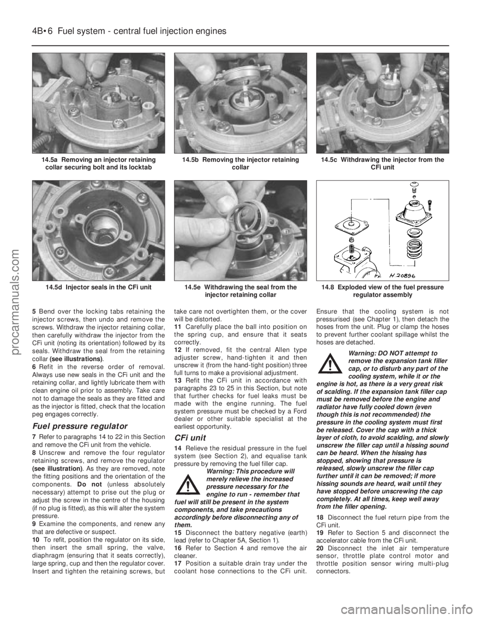
5Bend over the locking tabs retaining the
injector screws, then undo and remove the
screws. Withdraw the injector retaining collar,
then carefully withdraw the injector from the
CFi unit (noting its orientation) followed by its
seals. Withdraw the seal from the retaining
collar (see illustrations) .
6 Refit in the reverse order of removal.
Always use new seals in the CFi unit and the
retaining collar, and lightly lubricate them with
clean engine oil prior to assembly. Take care
not to damage the seals as they are fitted and
as the injector is fitted, check that the location
peg engages correctly.
Fuel pressure regulator
7 Refer to paragraphs 14 to 22 in this Section
and remove the CFi unit from the vehicle.
8 Unscrew and remove the four regulator
retaining screws, and remove the regulator
(see illustration) . As they are removed, note
the fitting positions and the orientation of the
components. Do not(unless absolutely
necessary) attempt to prise out the plug or
adjust the screw in the centre of the housing
(if no plug is fitted), as this will alter the system
pressure.
9 Examine the components, and renew any
that are defective or suspect.
10 To refit, position the regulator on its side,
then insert the small spring, the valve,
diaphragm (ensuring that it seats correctly),
large spring, cup and then the regulator cover.
Insert and tighten the retaining screws, but take care not overtighten them, or the cover
will be distorted.
11
Carefully place the ball into position on
the spring cup, and ensure that it seats
correctly.
12 If removed, fit the central Allen type
adjuster screw, hand-tighten it and then
unscrew it (from the hand-tight position) three
full turns to make a provisional adjustment.
13 Refit the CFi unit in accordance with
paragraphs 23 to 25 in this Section, but note
that further checks for fuel leaks must be
made with the engine running. The fuel
system pressure must be checked by a Ford
dealer or other suitable specialist at the
earliest opportunity.CFi unit
14 Relieve the residual pressure in the fuel
system (see Section 2), and equalise tank
pressure by removing the fuel filler cap. Warning: This procedure will
merely relieve the increased
pressure necessary for the
engine to run - remember that
fuel will still be present in the system
components, and take precautions
accordingly before disconnecting any of
them.
15 Disconnect the battery negative (earth)
lead (refer to Chapter 5A, Section 1).
16 Refer to Section 4 and remove the air
cleaner.
17 Position a suitable drain tray under the
coolant hose connections to the CFi unit. Ensure that the cooling system is not
pressurised (see Chapter 1), then detach the
hoses from the unit. Plug or clamp the hoses
to prevent further coolant spillage whilst the
hoses are detached.
Warning: DO NOT attempt to
remove the expansion tank filler
cap, or to disturb any part of the
cooling system, while it or the
engine is hot, as there is a very great risk
of scalding. If the expansion tank filler cap
must be removed before the engine and
radiator have fully cooled down (even
though this is not recommended) the
pressure in the cooling system must first
be released. Cover the cap with a thick
layer of cloth, to avoid scalding, and slowly
unscrew the filler cap until a hissing sound
can be heard. When the hissing has
stopped, showing that pressure is
released, slowly unscrew the filler cap
further until it can be removed; if more
hissing sounds are heard, wait until they
have stopped before unscrewing the cap
completely. At all times, keep well away
from the filler opening.
18 Disconnect the fuel return pipe from the
CFi unit.
19 Refer to Section 5 and disconnect the
accelerator cable from the CFi unit.
20 Disconnect the inlet air temperature
sensor, throttle plate control motor and
throttle position sensor wiring multi-plug
connectors.
4B•6 Fuel system - central fuel injection engines
14.8 Exploded view of the fuel pressure
regulator assembly14.5e Withdrawing the seal from theinjector retaining collar14.5d Injector seals in the CFi unit
14.5c Withdrawing the injector from the CFi unit14.5b Removing the injector retainingcollar14.5a Removing an injector retainingcollar securing bolt and its locktab
1595Ford Fiesta Remakeprocarmanuals.com
http://vnx.su
Page 132 of 296
worn. Apply a smear of anti-seize compound
to the sensor’s threads, to prevent them from
welding themselves to the downpipe in
service. Refit the sensor, tightening it to its
specified torque wrench setting; a slotted
socket will be required to do this. Reconnect
the wiring, and heat shield then refit the
connector plug.
Inlet manifold heater
57The heater is located in a recess in the
inlet manifold, directly underneath the CFi
unit. While access is possible from
underneath, it is preferable, depending on the
tools available, to remove the complete
manifold (Section 15) to reach the heater.
58 Assuming the work is being carried out
without removing the manifold, disconnect
the battery negative (earth) lead (refer to
Chapter 5A, Section 1).
59 Chock the rear wheels then jack up the
front of the car and support it on axle stands
(see “Jacking and vehicle support” ).
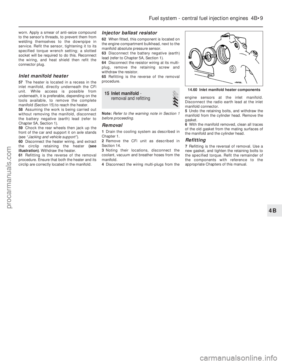
60 Disconnect the heater wiring, and extract
the circlip retaining the heater (see
illustration) . Withdraw the heater.
61 Refitting is the reverse of the removal
procedure. Ensure that both the heater and its
circlip are correctly located in the manifold.
Injector ballast resistor
62 When fitted, this component is located on
the engine compartment bulkhead, next to the
manifold absolute pressure sensor.
63 Disconnect the battery negative (earth)
lead (refer to Chapter 5A, Section 1).
64 Disconnect the resistor wiring at its multi-
plug, remove the retaining screw and
withdraw the resistor.
65 Refitting is the reverse of the removal
procedure.
15 Inlet manifold -
removal and refitting
3
Note: Refer to the warning note in Section 1
before proceeding.
Removal
1 Drain the cooling system as described in
Chapter 1.
2 Remove the CFi unit as described in
Section 14.
3 Noting their locations, disconnect the
coolant, vacuum and breather hoses from the
manifold.
4 Disconnect the wiring multi-plugs from the engine sensors at the inlet manifold.
Disconnect the radio earth lead at the inlet
manifold connector.
5
Undo the retaining bolts, and withdraw the
manifold from the cylinder head. Remove the
gasket.
6 With the manifold removed, clean all traces
of the old gasket from the mating surfaces of
the manifold and the cylinder head.
Refitting
7 Refitting is the reversal of removal. Use a
new gasket, and tighten the retaining bolts to
the specified torque. Refit the remainder of
the components with reference to the
appropriate Chapters of this manual.
Fuel system - central fuel injection engines 4B•9
14.60 Inlet manifold heater components
4B
1595Ford Fiesta Remakeprocarmanuals.com
http://vnx.su
Page 141 of 296
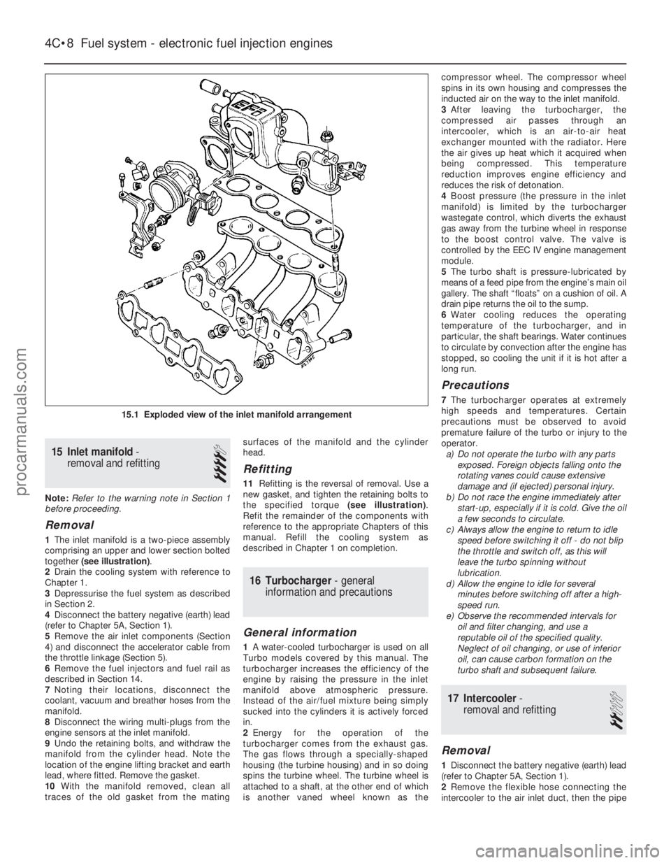
15 Inlet manifold-
removal and refitting
4
Note: Refer to the warning note in Section 1
before proceeding.
Removal
1 The inlet manifold is a two-piece assembly
comprising an upper and lower section bolted
together (see illustration) .
2 Drain the cooling system with reference to
Chapter 1.
3 Depressurise the fuel system as described
in Section 2.
4 Disconnect the battery negative (earth) lead
(refer to Chapter 5A, Section 1).
5 Remove the air inlet components (Section
4) and disconnect the accelerator cable from
the throttle linkage (Section 5).
6 Remove the fuel injectors and fuel rail as
described in Section 14.
7 Noting their locations, disconnect the
coolant, vacuum and breather hoses from the
manifold.
8 Disconnect the wiring multi-plugs from the
engine sensors at the inlet manifold.
9 Undo the retaining bolts, and withdraw the
manifold from the cylinder head. Note the
location of the engine lifting bracket and earth
lead, where fitted. Remove the gasket.
10 With the manifold removed, clean all
traces of the old gasket from the mating surfaces of the manifold and the cylinder
head.
Refitting
11
Refitting is the reversal of removal. Use a
new gasket, and tighten the retaining bolts to
the specified torque (see illustration).
Refit the remainder of the components with
reference to the appropriate Chapters of this
manual. Refill the cooling system as
described in Chapter 1 on completion.
16 Turbocharger - general
information and precautions
General information
1 A water-cooled turbocharger is used on all
Turbo models covered by this manual. The
turbocharger increases the efficiency of the
engine by raising the pressure in the inlet
manifold above atmospheric pressure.
Instead of the air/fuel mixture being simply
sucked into the cylinders it is actively forced
in.
2 Energy for the operation of the
turbocharger comes from the exhaust gas.
The gas flows through a specially-shaped
housing (the turbine housing) and in so doing
spins the turbine wheel. The turbine wheel is
attached to a shaft, at the other end of which
is another vaned wheel known as the compressor wheel. The compressor wheel
spins in its own housing and compresses the
inducted air on the way to the inlet manifold.
3
After leaving the turbocharger, the
compressed air passes through an
intercooler, which is an air-to-air heat
exchanger mounted with the radiator. Here
the air gives up heat which it acquired when
being compressed. This temperature
reduction improves engine efficiency and
reduces the risk of detonation.
4 Boost pressure (the pressure in the inlet
manifold) is limited by the turbocharger
wastegate control, which diverts the exhaust
gas away from the turbine wheel in response
to the boost control valve. The valve is
controlled by the EEC IV engine management
module.
5 The turbo shaft is pressure-lubricated by
means of a feed pipe from the engine’s main oil
gallery. The shaft “floats” on a cushion of oil. A
drain pipe returns the oil to the sump.
6 Water cooling reduces the operating
temperature of the turbocharger, and in
particular, the shaft bearings. Water continues
to circulate by convection after the engine has
stopped, so cooling the unit if it is hot after a
long run.
Precautions
7 The turbocharger operates at extremely
high speeds and temperatures. Certain
precautions must be observed to avoid
premature failure of the turbo or injury to the
operator. a) Do not operate the turbo with any parts
exposed. Foreign objects falling onto the
rotating vanes could cause extensive
damage and (if ejected) personal injury.
b) Do not race the engine immediately after
start-up, especially if it is cold. Give the oil
a few seconds to circulate.
c) Always allow the engine to return to idle
speed before switching it off - do not blip
the throttle and switch off, as this will
leave the turbo spinning without
lubrication.
d) Allow the engine to idle for several
minutes before switching off after a high-
speed run.
e) Observe the recommended intervals for oil and filter changing, and use a
reputable oil of the specified quality.
Neglect of oil changing, or use of inferior
oil, can cause carbon formation on the
turbo shaft and subsequent failure.
17 Intercooler -
removal and refitting
2
Removal
1 Disconnect the battery negative (earth) lead
(refer to Chapter 5A, Section 1).
2 Remove the flexible hose connecting the
intercooler to the air inlet duct, then the pipe
4C•8 Fuel system - electronic fuel injection engines
15.1 Exploded view of the inlet manifold arrangement
1595Ford Fiesta Remakeprocarmanuals.com
http://vnx.su
Page 142 of 296
and flexible hose connecting the turbocharger
to the intercooler (see illustration 4.12) . Use
adhesive tape to seal the turbocharger ports
against the entry of dirt.
3 Unbolt the horn nearest the intercooler.
4 Unbolt the radiator/intercooler assembly
from the bonnet closure panel and the body
crossmember.
5 Move the assembly as far as possible
towards the engine, and unbolt the intercooler
from the radiator; withdraw the intercooler.
Refitting
6 Refitting is the reverse of the removal
procedure, tightening all nuts and bolts to the
specified torque settings, and not forgetting
to unseal the turbocharger openings before
reconnecting the intercooler pipe and hose.
18 Turbocharger boost control valve - removal and refitting
2
Removal
1Disconnect the battery negative (earth) lead
(refer to Chapter 5A, Section 1).
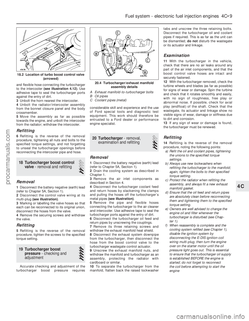
2 Disconnect the control valve wiring at its
multi-plug (see illustration) .
3 Marking or labelling the valve hoses so that
each can be reconnected to its original union,
disconnect the hoses from the valve.
4 Remove the securing screws and withdraw
the valve.
Refitting
5 Refitting is the reverse of the removal
procedure; tighten the screws to the specified
torque setting.
19 Turbocharger boost pressure - checking and
adjustment
5
Accurate checking and adjustment of the
turbocharger boost pressure requires considerable skill and experience and the use
of Ford special tools and diagnostic test
equipment. This work should therefore be
entrusted to a Ford dealer or performance
engine specialist.
20 Turbocharger
- removal,
examination and refitting
3
Removal
1 Disconnect the battery negative (earth) lead
(refer to Chapter 5A, Section 1).
2 Drain the cooling system as described in
Chapter 1.
3 Remove the air inlet components as
described in Section 4.
4 Disconnect the turbocharger coolant feed
and return hoses by slackening the clamps
and pulling the hoses off the turbocharger’s
metal pipes (see illustration) .
5 Remove the pipe and flexible hoses
connecting the turbocharger to the air cleaner
and intercooler. Use adhesive tape to seal the
turbocharger ports against the entry of dirt.
6 Disconnect the turbocharger oil feed and
return pipes by unscrewing the couplings.
7 Remove its three retaining screws and
withdraw the exhaust manifold heat shield.
8 Disconnect the exhaust system downpipe
from the turbocharger, then disconnect the
hose from the boost control valve to the
turbocharger wastegate control actuator.
9 Unscrew the exhaust manifold nuts, and
withdraw the manifold and turbocharger as an
assembly, protecting the radiator with
cardboard or similar.
10 To separate the turbocharger from the
manifold, flatten back the raised lockwasher tabs and unscrew the three retaining bolts.
Disconnect the turbocharger oil and coolant
pipes if required. This is as far as the unit can
be dismantled;
do notdisturb the wastegate
or its actuator and linkage.
Examination
11 With the turbocharger in the vehicle,
check that there are no air leaks around any
part of the air inlet components, and that the
boost control valve hoses are intact and
securely fastened.
12 With the turbocharger removed, check the
turbine wheels and blades (as far as possible)
for signs of wear or damage. Spin the turbine
and check that it rotates smoothly and easily,
with no sign of roughness, free play or
abnormal noise. If possible, check for axial
play (endfloat) of the shaft. Check that the
wastegate, its actuator and linkage show no
visible signs of wear, damage or stiffness due
to dirt and corrosion.
13 If any sign of wear or damage is found,
the turbocharger must be renewed.
Refitting
14 Refitting is the reverse of the removal
procedure, noting the following points: a) Refit the oil and coolant pipes, tightening
the unions to the specified torque
settings.
b) Always use new lockwashers when
refitting the turbocharger to the manifold;
again, tighten the bolts to their specified
torque setting.
c) Protect the radiator when refitting the
assembly, and always fit a new exhaust
manifold gasket.
d) Ensure that the oil feed and return pipes
are absolutely clean before reconnecting
them and tightening them to the specified
torque setting.
e) Owners are well advised to change the engine oil and filter whenever the
turbocharger is disturbed (see Chap-
ter 1).
f) When reassembly is complete and the
cooling system refilled (see Chapter 1),
disable the ignition system by
disconnecting the E-DIS ignition coil
wiring multi-plug, then turn the engine
over on the starter motor until the oil
pressure light goes out. This is essential
to ensure that the turbocharger oil supply
is established BEFORE the engine is
started; do not forget to reconnect
the coil before attempting to start the
engine
Fuel system - electronic fuel injection engines 4C•9
20.4 Turbocharger/exhaust manifold assembly details
A Exhaust manifold-to-turbocharger bolts
B Oil pipes
C Coolant pipes (metal)
4C
1595Ford Fiesta Remake
18.2 Location of turbo boost control valve (arrowed)
procarmanuals.com
http://vnx.su
Page 148 of 296
and gasket. Discard the gasket - this must be
renewed whenever it is disturbed.
7Refit in the reverse order of removal. Check
that the mating faces are clean, and fit a new
gasket. Adjust the accelerator cable as
described in Section 5 on completion.
Fuel rail and injectors
Note: The following procedure is applicable
mainly to Zetec engines; specific information
for the PTE engine was not available at the
time of writing. However, apart from minor
differences in component attachments, both
engine types are very similar in this area.
8 Relieve the residual pressure in the fuel
system (see Section 2), and equalise tank
pressure by removing the fuel filler cap. Warning: This procedure will
merely relieve the increased
pressure necessary for the
engine to run - remember that
fuel will still be present in the system
components, and take precautions
accordingly before disconnecting any of
them.
9 Disconnect the battery negative (earth) lead
- see Chapter 5A, Section 1.
10 Remove the air inlet components as
described in Section 4.
11 Disconnect the accelerator cable from the
throttle linkage (see Section 5).
12 Disconnect the throttle position sensor
multi-plug.
13 Remove the throttle housing mounting
screws, then detach the throttle housing and gasket from the inlet manifold. Discard the
gasket - this must be renewed whenever it is
disturbed.
14
Detach the crankcase breather hose from
the cylinder head cover, and the fuel pressure
regulator vacuum hose from the inlet
manifold.
15 Releasing the wire clips, unplug the four
fuel injector multi-plugs and the inlet air
temperature sensor multi-plug.
16 Refer to Section 3 and disconnect the fuel
feed and return lines at the quick-release
couplings, then unclip the fuel hoses from the
inlet manifold; use rag to soak up any spilt
fuel. Note: Do not disturb the threaded
couplings at the fuel rail unions unless
absolutely necessary; these are sealed at the
factory. The quick-release couplings will
suffice for all normal service operations.
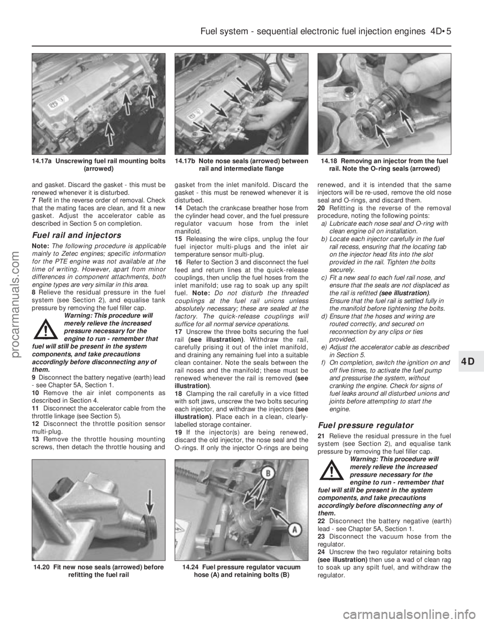
17 Unscrew the three bolts securing the fuel
rail (see illustration) . Withdraw the rail,
carefully prising it out of the inlet manifold,
and draining any remaining fuel into a suitable
clean container. Note the seals between the
rail noses and the manifold; these must be
renewed whenever the rail is removed (see
illustration) .
18 Clamping the rail carefully in a vice fitted
with soft jaws, unscrew the two bolts securing
each injector, and withdraw the injectors (see
illustration) . Place each in a clean, clearly-
labelled storage container.
19 If the injector(s) are being renewed,
discard the old injector, the nose seal and the
O- rings. If only the injector O-rings are being renewed, and it is intended that the same
injectors will be re-used, remove the old nose
seal and O-rings, and discard them.
20
Refitting is the reverse of the removal
procedure, noting the following points:
a) Lubricate each nose seal and O-ring with clean engine oil on installation.
b) Locate each injector carefully in the fuel
rail recess, ensuring that the locating tab
on the injector head fits into the slot
provided in the rail. Tighten the bolts
securely.
c) Fit a new seal to each fuel rail nose, and
ensure that the seals are not displaced as
the rail is refitted (see illustration).
Ensure that the fuel rail is settled fully in
the manifold before tightening the bolts.
d) Ensure that the hoses and wiring are
routed correctly, and secured on
reconnection by any clips or ties
provided.
e) Adjust the accelerator cable as described
in Section 5.
f) On completion, switch the ignition on and off five times, to activate the fuel pump
and pressurise the system, without
cranking the engine. Check for signs of
fuel leaks around all disturbed unions and
joints before attempting to start the
engine.
Fuel pressure regulator
21 Relieve the residual pressure in the fuel
system (see Section 2), and equalise tank
pressure by removing the fuel filler cap.
Warning: This procedure will
merely relieve the increased
pressure necessary for the
engine to run - remember that
fuel will still be present in the system
components, and take precautions
accordingly before disconnecting any of
them.
22 Disconnect the battery negative (earth)
lead - see Chapter 5A, Section 1.
23 Disconnect the vacuum hose from the
regulator.
24 Unscrew the two regulator retaining bolts
(see illustration) then use a wad of clean rag
to soak up any spilt fuel, and withdraw the
regulator.
Fuel system - sequential electronic fuel injection engines 4D•5
14.18 Removing an injector from the fuel rail. Note the O-ring seals (arrowed)14.17b Note nose seals (arrowed) between rail and intermediate flange14.17a Unscrewing fuel rail mounting bolts (arrowed)
14.24 Fuel pressure regulator vacuumhose (A) and retaining bolts (B)14.20 Fit new nose seals (arrowed) before refitting the fuel rail
4D
1595Ford Fiesta Remakeprocarmanuals.com
http://vnx.su
Page 150 of 296
b)Tighten the screws evenly and securely
(but do not overtighten them, or the
potentiometer body will be cracked).
Vehicle speed sensor
48 The sensor is mounted at the base of the
speedometer drive cable, and is removed with
the speedometer drive pinion. Refer to the
relevant Section of Chapter 7A or B, as
applicable.
Power steering pressure switch
49 Releasing its clip, unplug the switch’s
electrical connector, then unscrew the switch
from the power steering high pressure pipe.
Place a wad of rag underneath, to catch any
spilt fluid. If a sealing washer is fitted, renew it
if it is worn or damaged.
50 Refitting is the reverse of the removal
procedure; tighten the switch securely, then
top-up the fluid reservoir (see “Weekly
Checks”) to replace any fluid lost from the
system, and bleed out any trapped air (see
Chapter 10).
Oxygen sensor
Note: The sensor is delicate, and will not work
if it is dropped or knocked, if its power supply
is disrupted, or if any cleaning materials are
used on it.
51 Raise and support the front of the vehicle
if required to remove the sensor from
underneath (“see Jacking and vehicle
support” ).
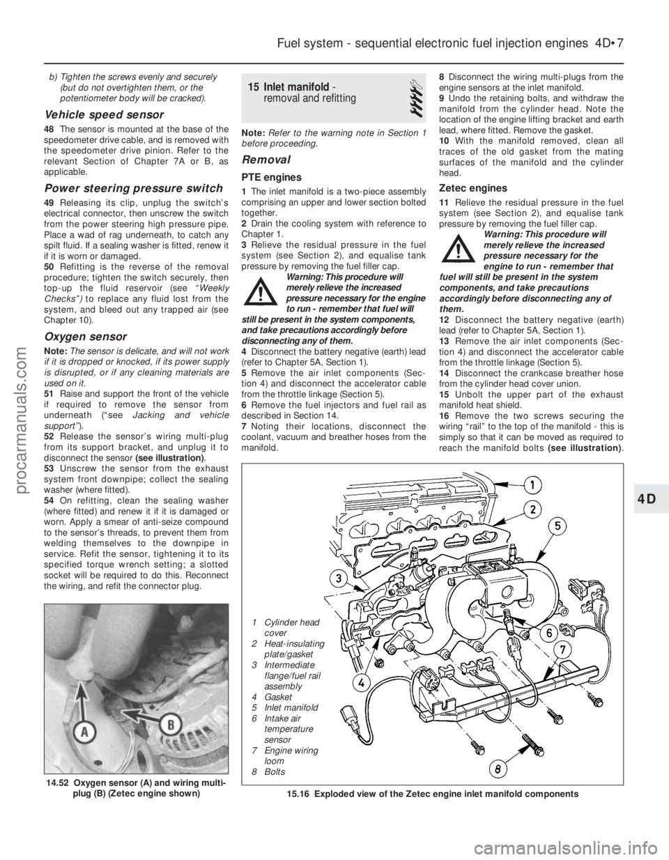
52 Release the sensor’s wiring multi-plug
from its support bracket, and unplug it to
disconnect the sensor (see illustration).
53 Unscrew the sensor from the exhaust
system front downpipe; collect the sealing
washer (where fitted).
54 On refitting, clean the sealing washer
(where fitted) and renew it if it is damaged or
worn. Apply a smear of anti-seize compound
to the sensor’s threads, to prevent them from
welding themselves to the downpipe in
service. Refit the sensor, tightening it to its
specified torque wrench setting; a slotted
socket will be required to do this. Reconnect
the wiring, and refit the connector plug.
15 Inlet manifold -
removal and refitting
4
Note: Refer to the warning note in Section 1
before proceeding.
Removal
PTE engines
1 The inlet manifold is a two-piece assembly
comprising an upper and lower section bolted
together.
2 Drain the cooling system with reference to
Chapter 1.
3 Relieve the residual pressure in the fuel
system (see Section 2), and equalise tank
pressure by removing the fuel filler cap. Warning: This procedure will
merely relieve the increased
pressure necessary for the engine
to run - remember that fuel will
still be present in the system components,
and take precautions accordingly before
disconnecting any of them.
4 Disconnect the battery negative (earth) lead
(refer to Chapter 5A, Section 1).
5 Remove the air inlet components (Sec-
tion 4) and disconnect the accelerator cable
from the throttle linkage (Section 5).
6 Remove the fuel injectors and fuel rail as
described in Section 14.
7 Noting their locations, disconnect the
coolant, vacuum and breather hoses from the
manifold. 8
Disconnect the wiring multi-plugs from the
engine sensors at the inlet manifold.
9 Undo the retaining bolts, and withdraw the
manifold from the cylinder head. Note the
location of the engine lifting bracket and earth
lead, where fitted. Remove the gasket.
10 With the manifold removed, clean all
traces of the old gasket from the mating
surfaces of the manifold and the cylinder
head.Zetec engines
11 Relieve the residual pressure in the fuel
system (see Section 2), and equalise tank
pressure by removing the fuel filler cap. Warning: This procedure will
merely relieve the increased
pressure necessary for the
engine to run - remember that
fuel will still be present in the system
components, and take precautions
accordingly before disconnecting any of
them.
12 Disconnect the battery negative (earth)
lead (refer to Chapter 5A, Section 1).
13 Remove the air inlet components (Sec-
tion 4) and disconnect the accelerator cable
from the throttle linkage (Section 5).
14 Disconnect the crankcase breather hose
from the cylinder head cover union.
15 Unbolt the upper part of the exhaust
manifold heat shield.
16 Remove the two screws securing the
wiring “rail” to the top of the manifold - this is
simply so that it can be moved as required to
reach the manifold bolts (see illustration).
Fuel system - sequential electronic fuel injection engines 4D•7
14.52 Oxygen sensor (A) and wiring multi-
plug (B) (Zetec engine shown)15.16 Exploded view of the Zetec engine inlet manifold components
4D
1595Ford Fiesta Remake
1 Cylinder head
cover
2 Heat-insulating plate/gasket
3 Intermediate flange/fuel rail
assembly
4 Gasket
5 Inlet manifold
6 Intake air temperature
sensor
7 Engine wiring
loom
8 Boltsprocarmanuals.com
http://vnx.su
Page 151 of 296
Unplug the electrical connectors at the
camshaft position sensor and the coolant
temperature sensor, then unclip the wiring
from the ignition coil bracket, and secure it to
the manifold.
17Remove the three screws securing the
wiring “rail” to the rear of the manifold.
Releasing its wire clip, unplug the large
electrical connector (next to the fuel pressure
regulator) to disconnect the wiring of the
manifold components from the engine wiring
loom.
18 Marking or labelling them as they are
unplugged, disconnect the vacuum hoses at
the manifold and throttle housing.
19 Undo the fuel feed and return lines
connecting the engine to the chassis. Plug or
cap all open fittings. 20
Unbolt the earth lead from the cylinder
head rear support plate/engine lifting eye,
then unscrew the bolt securing the support
plate/lifting eye.
21 Unscrew the nuts and bolts securing the
manifold to the cylinder head, and withdraw it.
Take care not to damage vulnerable
components as the manifold assembly is
manoeuvred out of the engine compartment.
22 With the manifold removed, clean all
traces of the old gasket from the mating
surfaces of the manifold and the cylinder head.
Refitting
All engines
23 Refitting is the reverse of the removal
procedure, noting the following points: a) Fit a new gasket, then locate the manifold on the head and install the nuts and bolts.
b) Tighten the nuts/bolts in three or four
equal steps to the specified torque,
working from the centre outwards, to
avoid warping the manifold.
c) Refit the remaining parts in the reverse order of removal - tighten all fasteners to
the torque wrench settings specified
(where given).
d) Where drained, refill the cooling system
as described in Chapter 1.
e) Before starting the engine, check the accelerator cable for correct adjustment
and the throttle linkage for smooth
operation (Section 5).
f) When the engine is fully warmed-up,
check for signs of fuel, inlet and/or
vacuum leaks.
4D•8 Fuel system - sequential electronic fuel injection engines
1595Ford Fiesta Remakeprocarmanuals.com
http://vnx.su
Page 155 of 296
2The exhaust manifold is secured the
cylinder head by studs and nuts, and is
similarly attached to the exhaust downpipe. A
shroud/heat shield is bolted to the manifold,
to direct exhaust-heated air into the air inlet
system when the engine is cold. Access to the
exhaust manifold retaining nuts is gained by
first removing this shroud (see illustration).
3 On vehicles equipped with a pulse-air
system, remove the pulse-air piping as
described in Section 7.
4 Support the exhaust downpipe on a jack or
suitable blocks, and undo the downpipe-to-
manifold retaining nuts. Separate the pipe
from the manifold, and remove the gasket. On
catalytic converter-equipped vehicles with an
oxygen sensor fitted to the exhaust
downpipe, take care not to stretch the sensor
wiring; if necessary, disconnect the sensor’s
multi-plug.
5 Undo the retaining nuts, and withdraw the
manifold from the cylinder head studs.
Remove the manifold gasket.Zetec enginesNote: In addition to the new gasket and any
other parts, tools or facilities needed to carry
out this operation, a new plastic guide sleeve
will be required on reassembly.
6 Disconnect the battery negative (earth) lead
- see Chapter 5A, Section 1.
7 Remove the air inlet components as
described in Part D of this Chapter.
8 Drain the cooling system (see Chapter 1).
9 Disconnect the coolant hose and the
coolant pipe/hose from the thermostat
housing; secure them clear of the working
area.
10 Unbolt the exhaust manifold heat shield,
and withdraw both parts of the shield (see
illustration) .
11 While the manifold can be removed with
the pulse-air system components attached -
unbolt the filter housing and disconnect its
vacuum hose if this is to be done - it is easier
to remove the pulse-air assembly first, as
described in Section 7. 12
Unplug the oxygen sensor electrical
connector, to avoid straining its wiring.
Unscrew the nuts to disconnect the exhaust
system front downpipe from the manifold.
13 Remove the nuts and detach the manifold
and gasket (see illustration) . When removing
the manifold with the engine in the vehicle,
additional clearance can be obtained by
unscrewing the studs from the cylinder head;
a female Torx-type socket will be required.
14 Always fit a new gasket on reassembly, to
carefully-cleaned components. Do not
attempt to re-use the original gasket.
Inspection
15 Use a scraper to remove all traces of old
gasket material and carbon deposits from the
manifold and cylinder head mating surfaces.
Provided both mating surfaces are clean and
flat, a new gasket will be sufficient to ensure
that the joint is gastight. Do not use any kind
of exhaust sealant upstream of the catalytic
converter, where fitted.
16 Note that on some models, the downpipe is
secured to the manifold by two bolts, with a coil
spring, spring seat and self-locking nut on each.
On refitting, tighten the nuts until they stop on
the bolt shoulders; the pressure of the springs
will then suffice to make a gastight joint.
17 Do not overtighten the nuts to cure a leak -
the bolts will shear; renew the gasket and the
springs if a leak is found. The bolts themselves
are secured by spring clips to the manifold,
and can be renewed easily if damaged.
Refitting
18 Refitting is the reverse of the removal
procedure, noting the following points: a) Position a new gasket over the cylinder head studs, and on Zetec engines, fit a
new plastic guide sleeve to the stud
nearest to the thermostat housing, so that
the manifold will be correctly located (see
illustration) . Do notrefit the manifold
without this sleeve.
b) Refit the manifold, and finger-tighten the
mounting nuts.
c) Working from the centre out, and in three or four equal steps, tighten the nuts to the
torque wrench settings given in the
Specifications.
4E•4 Exhaust and emission control systems
3.18 Fit a new plastic guide sleeve to the
stud (arrowed) when refitting the manifold
(Zetec engine models)3.13 Exhaust manifold retaining nuts(Zetec engine models)3.10 Exhaust manifold heat shield bolts(arrowed) (Zetec engine models)
3.2 Exploded view of the exhaust manifold arrangement (1.6 litre CVH E\
Fi engine models)
1 Retaining stud
2 Gasket
3 Heatshield 4 Exhaust manifold
5 Manifold retaining nut
6 Centring hole 7 Heatshield retaining bolt
8 Cylinder head
1595Ford Fiesta Remakeprocarmanuals.com
http://vnx.su