driver seat adjustment FORD FIESTA 1989 Service Repair Manual
[x] Cancel search | Manufacturer: FORD, Model Year: 1989, Model line: FIESTA, Model: FORD FIESTA 1989Pages: 296, PDF Size: 10.65 MB
Page 127 of 296
4 Air cleaner assembly and airinlet components -
removal and refitting
1
Note: Air cleaner element renewal and air
cleaner temperature control system checks
(where applicable) are described in Chapter 1.
Air cleaner assembly
1 Disconnect the battery negative (earth) lead
(refer to Chapter 5A, Section 1).
2 Undo the retaining bolts and partially lift the
air cleaner from the CFi unit, so that the hose
and wiring connections to the underside of
the air cleaner body are accessible.
3 Note their connections and routings, then
detach the wiring and hoses from the
underside of the air cleaner.
4 Lift the air cleaner clear from the CFi unit.
5 Refit in the reverse order of removal.
6 Renew any hoses that are perished or
cracked, and ensure that all fittings are
securely and correctly reconnected.
Air inlet components
7 The air cleaner inlet spout and related
components are removed with the air cleaner
assembly as described above.
5 Accelerator cable - removal,
refitting and adjustment
1
Removal
1 Disconnect the battery negative (earth) lead
(refer to Chapter 5A, Section 1).
2 Fold back the carpet and insulation in the
driver’s footwell to gain access to the
accelerator pedal.
3 Detach the accelerator cable from the
pedal.
4 Remove the air cleaner assembly as
described in Section 4.
5 Working at the throttle housing end of the
cable, pivot the throttle quadrant by hand to
release the tension from the cable, then
detach the inner cable nipple from the throttle
lever.
6 Detach the outer cable from the
adjuster/support bracket, then remove the
cable.
Refitting and adjustment
7 Refit in the reverse order of removal. When
the cable is reconnected at each end, have an
assistant depress the accelerator, and check
that the throttle fully opens and shuts without
binding. Ensure that there is a small amount of
slack in the inner cable when the throttle is
fully released. If adjustment is required,
release the outer cable retaining clip from the
cable at the adjustment/support bracket, slide
the cable through the adjuster grommet to the
point required, then refit the retaining clip to
secure it in the set position.
6 Accelerator pedal -
removal and refitting
1
Refer to Part A, Section 5.
7 Fuel pump/fuel pressure -
checking
3
Note: Refer to the warning note in Section 1
before proceeding.
Fuel pump operation check
1 Switch on the ignition, and listen for the fuel
pump (the sound of an electric motor running,
audible from beneath the rear seats). Assuming
there is sufficient fuel in the tank, the pump
should start and run for approximately one or
two seconds, then stop, each time the ignition
is switched on. Note:If the pump runs
continuously all the time the ignition is switched
on, the electronic control system is running in
the backup (or “limp-home”) mode referred to
by Ford as “Limited Operation Strategy” (LOS).
This almost certainly indicates a fault in the
EEC IV module itself, and the vehicle should
therefore be taken to a Ford dealer for a full test
of the complete system, using the correct
diagnostic equipment; do not waste time or risk
damaging the components by trying to test the
system without such facilities.
2 Listen for fuel return noises from the fuel
pressure regulator. It should be possible to
feel the fuel pulsing in the regulator and in the
feed hose from the fuel filter.
3 If the pump does not run at all, check the
fuse, relay and wiring (see Chapter 12). Check
also that the fuel cut-off switch has not been
activated and if so, reset it.
Fuel pressure check
4 A fuel pressure gauge will be required for this
check and should be connected in the fuel line
between the fuel filter and the CFi unit, in
accordance with the gauge maker’s instructions.
5 Start the engine and allow it to idle. Note
the gauge reading as soon as the pressure
stabilises, and compare it with the figures
given for regulated fuel pressure in the
Specifications . If the pressure is high, check
for a restricted fuel return line. If the pressure
is low, renew the fuel pressure regulator. 6
Switch off the engine, and check that after
one minute, the hold pressure has not fallen
below that specified. If it has, check the seals
on the fuel injector (see Section 14) and renew
them if they appear in any way suspect. If the
seals are okay, then the fuel pressure
regulator or CFi unit are suspect.
7 Carefully disconnect the fuel pressure
gauge, depressurising the system first as
described in Section 2.
8 Run the engine, and check that there are no
fuel leaks.
8 Fuel tank - removal,
inspection and refitting
3
Proceed as described in Part A, Section 8, but
before disconnecting the battery, relieve the
residual pressure in the fuel system (see Sec-
tion 2), and equalise tank pressure by removing
the fuel filler cap. Note also that it will be
necessary to release any additional ventilation
tubes from their retaining clips, and to reposition
or remove the underbody heat shields on certain
models for access to the tank retaining bolts.
9 Fuel pump/fuel gauge
sender unit - removal and
refitting
3
Note: Refer to the warning note in Section 1
before proceeding. Ford specify the use of their
service tool 23-026 (a large box spanner with
projecting teeth to engage the fuel pump/sender
unit retaining ring’s slots) for this task. While
alternatives are possible, in view of the difficulty
experienced in removing and refitting the
pump/sender unit, it is strongly advised that the
correct tool is obtained before starting work.
Removal
1 A combined fuel pump and fuel gauge
sender unit are located in the top face of the
fuel tank. The combined unit can only be
detached and withdrawn from the tank after
the tank is released and lowered from
under the vehicle. Refer to Section 8 and
remove the fuel tank, then proceed as follows.
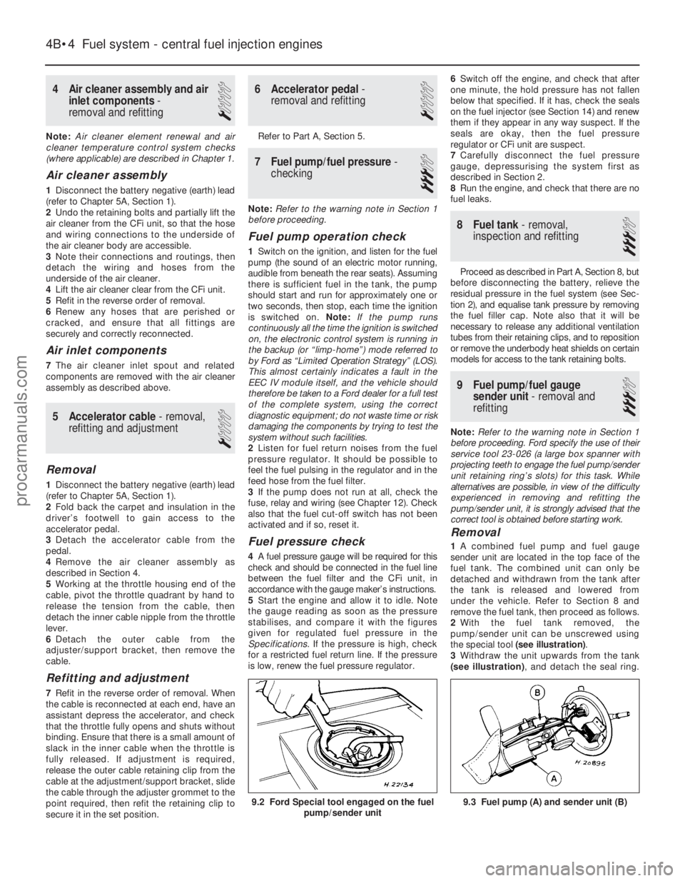
2 With the fuel tank removed, the
pump/sender unit can be unscrewed using
the special tool (see illustration) .
3 Withdraw the unit upwards from the tank
(see illustration) , and detach the seal ring.
9.3 Fuel pump (A) and sender unit (B)
4B•4 Fuel system - central fuel injection engines
9.2 Ford Special tool engaged on the fuel
pump/sender unit
1595Ford Fiesta Remakeprocarmanuals.com
http://vnx.su
Page 137 of 296
11On non-Turbo models, disconnect the
flexible hose between the air cleaner lid and
the air inlet duct.
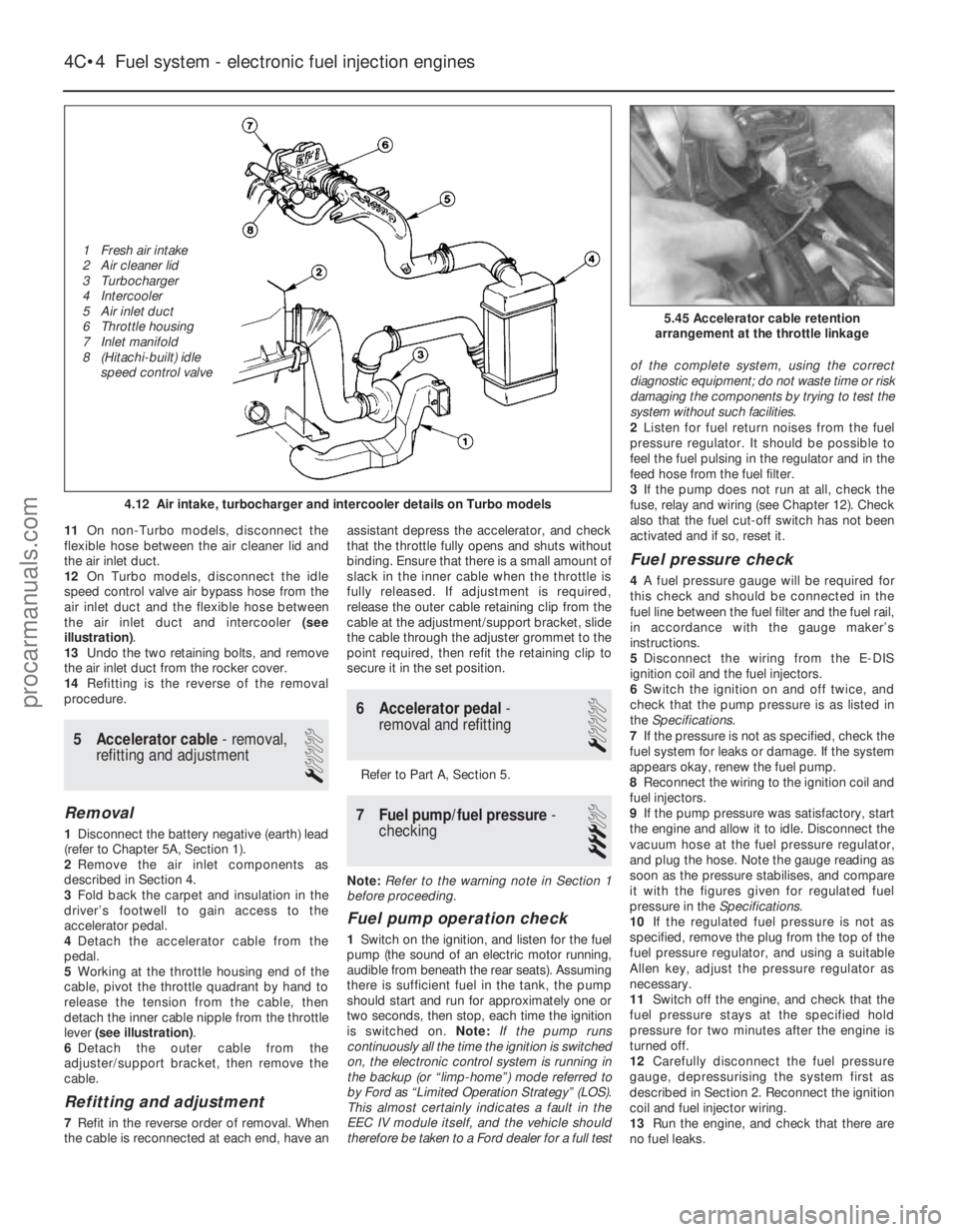
12 On Turbo models, disconnect the idle
speed control valve air bypass hose from the
air inlet duct and the flexible hose between
the air inlet duct and intercooler (see
illustration) .
13 Undo the two retaining bolts, and remove
the air inlet duct from the rocker cover.
14 Refitting is the reverse of the removal
procedure.
5 Accelerator cable - removal,
refitting and adjustment
1
Removal
1 Disconnect the battery negative (earth) lead
(refer to Chapter 5A, Section 1).
2 Remove the air inlet components as
described in Section 4.
3 Fold back the carpet and insulation in the
driver’s footwell to gain access to the
accelerator pedal.
4 Detach the accelerator cable from the
pedal.
5 Working at the throttle housing end of the
cable, pivot the throttle quadrant by hand to
release the tension from the cable, then
detach the inner cable nipple from the throttle
lever (see illustration) .
6 Detach the outer cable from the
adjuster/support bracket, then remove the
cable.
Refitting and adjustment
7 Refit in the reverse order of removal. When
the cable is reconnected at each end, have an assistant depress the accelerator, and check
that the throttle fully opens and shuts without
binding. Ensure that there is a small amount of
slack in the inner cable when the throttle is
fully released. If adjustment is required,
release the outer cable retaining clip from the
cable at the adjustment/support bracket, slide
the cable through the adjuster grommet to the
point required, then refit the retaining clip to
secure it in the set position.
6 Accelerator pedal
-
removal and refitting
1
Refer to Part A, Section 5.
7 Fuel pump/fuel pressure -
checking
3
Note: Refer to the warning note in Section 1
before proceeding.
Fuel pump operation check
1 Switch on the ignition, and listen for the fuel
pump (the sound of an electric motor running,
audible from beneath the rear seats). Assuming
there is sufficient fuel in the tank, the pump
should start and run for approximately one or
two seconds, then stop, each time the ignition
is switched on. Note:If the pump runs
continuously all the time the ignition is switched
on, the electronic control system is running in
the backup (or “limp-home”) mode referred to
by Ford as “Limited Operation Strategy” (LOS).
This almost certainly indicates a fault in the
EEC IV module itself, and the vehicle should
therefore be taken to a Ford dealer for a full test of the complete system, using the correct
diagnostic equipment; do not waste time or risk
damaging the components by trying to test the
system without such facilities.
2
Listen for fuel return noises from the fuel
pressure regulator. It should be possible to
feel the fuel pulsing in the regulator and in the
feed hose from the fuel filter.
3 If the pump does not run at all, check the
fuse, relay and wiring (see Chapter 12). Check
also that the fuel cut-off switch has not been
activated and if so, reset it.
Fuel pressure check
4 A fuel pressure gauge will be required for
this check and should be connected in the
fuel line between the fuel filter and the fuel rail,
in accordance with the gauge maker’s
instructions.
5 Disconnect the wiring from the E-DIS
ignition coil and the fuel injectors.
6 Switch the ignition on and off twice, and
check that the pump pressure is as listed in
the Specifications .
7 If the pressure is not as specified, check the
fuel system for leaks or damage. If the system
appears okay, renew the fuel pump.
8 Reconnect the wiring to the ignition coil and
fuel injectors.
9 If the pump pressure was satisfactory, start
the engine and allow it to idle. Disconnect the
vacuum hose at the fuel pressure regulator,
and plug the hose. Note the gauge reading as
soon as the pressure stabilises, and compare
it with the figures given for regulated fuel
pressure in the Specifications.
10 If the regulated fuel pressure is not as
specified, remove the plug from the top of the
fuel pressure regulator, and using a suitable
Allen key, adjust the pressure regulator as
necessary.
11 Switch off the engine, and check that the
fuel pressure stays at the specified hold
pressure for two minutes after the engine is
turned off.
12 Carefully disconnect the fuel pressure
gauge, depressurising the system first as
described in Section 2. Reconnect the ignition
coil and fuel injector wiring.
13 Run the engine, and check that there are
no fuel leaks.
4C•4 Fuel system - electronic fuel injection engines
5.45 Accelerator cable retention
arrangement at the throttle linkage
4.12 Air intake, turbocharger and intercooler details on Turbo models
1595Ford Fiesta Remake
1 Fresh air intake
2 Air cleaner lid
3 Turbocharger
4 Intercooler
5 Air inlet duct
6 Throttle housing
7 Inlet manifold
8 (Hitachi-built) idle
speed control valveprocarmanuals.com
http://vnx.su
Page 146 of 296
4 Air cleaner assembly and airinlet components - removal
and refitting
1
Air cleaner assembly
1 Disconnect the battery negative (earth) lead
(refer to Chapter 5A, Section 1).
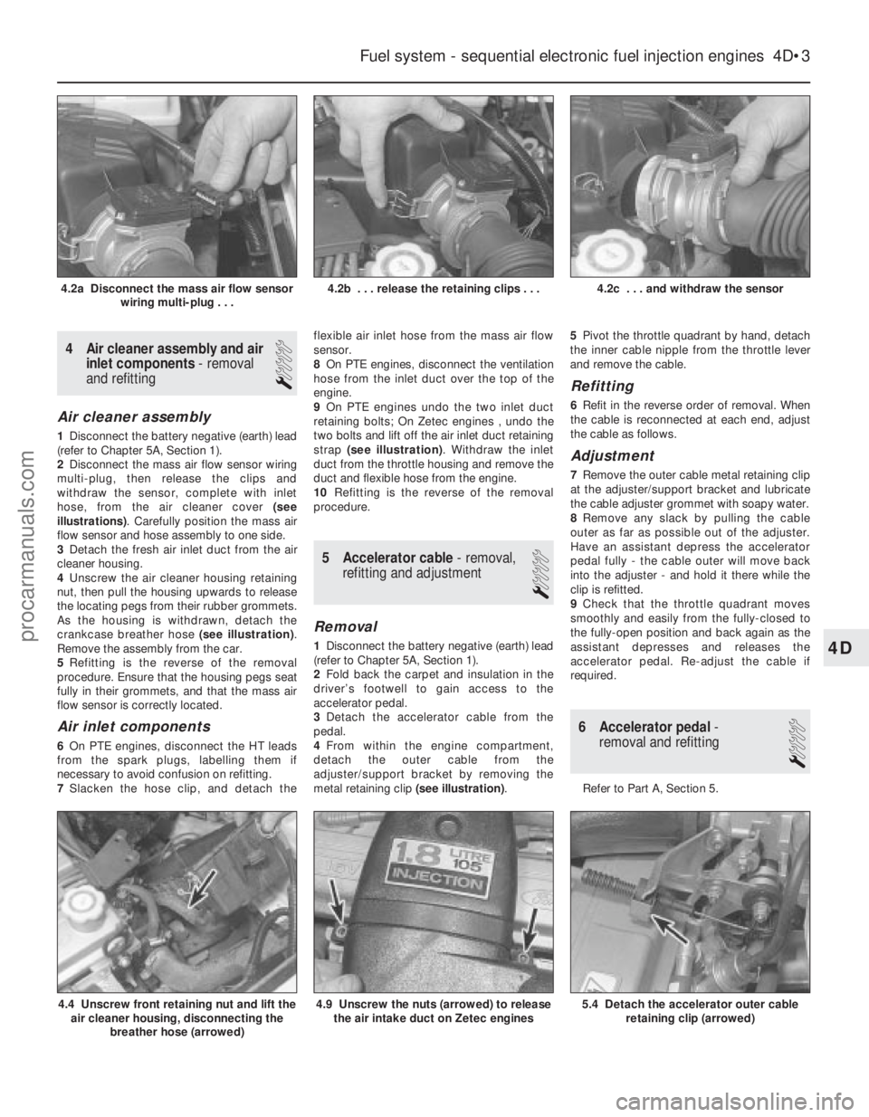
2 Disconnect the mass air flow sensor wiring
multi-plug, then release the clips and
withdraw the sensor, complete with inlet
hose, from the air cleaner cover (see
illustrations) . Carefully position the mass air
flow sensor and hose assembly to one side.
3 Detach the fresh air inlet duct from the air
cleaner housing.
4 Unscrew the air cleaner housing retaining
nut, then pull the housing upwards to release
the locating pegs from their rubber grommets.
As the housing is withdrawn, detach the
crankcase breather hose (see illustration).
Remove the assembly from the car.
5 Refitting is the reverse of the removal
procedure. Ensure that the housing pegs seat
fully in their grommets, and that the mass air
flow sensor is correctly located.
Air inlet components
6 On PTE engines, disconnect the HT leads
from the spark plugs, labelling them if
necessary to avoid confusion on refitting.
7 Slacken the hose clip, and detach the flexible air inlet hose from the mass air flow
sensor.
8
On PTE engines, disconnect the ventilation
hose from the inlet duct over the top of the
engine.
9 On PTE engines undo the two inlet duct
retaining bolts; On Zetec engines , undo the
two bolts and lift off the air inlet duct retaining
strap (see illustration) . Withdraw the inlet
duct from the throttle housing and remove the
duct and flexible hose from the engine.
10 Refitting is the reverse of the removal
procedure.
5 Accelerator cable - removal,
refitting and adjustment
1
Removal
1 Disconnect the battery negative (earth) lead
(refer to Chapter 5A, Section 1).
2 Fold back the carpet and insulation in the
driver’s footwell to gain access to the
accelerator pedal.
3 Detach the accelerator cable from the
pedal.
4 From within the engine compartment,
detach the outer cable from the
adjuster/support bracket by removing the
metal retaining clip (see illustration).5
Pivot the throttle quadrant by hand, detach
the inner cable nipple from the throttle lever
and remove the cable.
Refitting
6 Refit in the reverse order of removal. When
the cable is reconnected at each end, adjust
the cable as follows.
Adjustment
7 Remove the outer cable metal retaining clip
at the adjuster/support bracket and lubricate
the cable adjuster grommet with soapy water.
8 Remove any slack by pulling the cable
outer as far as possible out of the adjuster.
Have an assistant depress the accelerator
pedal fully - the cable outer will move back
into the adjuster - and hold it there while the
clip is refitted.
9 Check that the throttle quadrant moves
smoothly and easily from the fully-closed to
the fully-open position and back again as the
assistant depresses and releases the
accelerator pedal. Re-adjust the cable if
required.
6 Accelerator pedal -
removal and refitting
1
Refer to Part A, Section 5.
Fuel system - sequential electronic fuel injection engines 4D•3
4.2c . . . and withdraw the sensor4.2b . . . release the retaining clips . . .4.2a Disconnect the mass air flow sensor
wiring multi-plug . . .
5.4 Detach the accelerator outer cableretaining clip (arrowed)4.9 Unscrew the nuts (arrowed) to releasethe air intake duct on Zetec engines4.4 Unscrew front retaining nut and lift theair cleaner housing, disconnecting the
breather hose (arrowed)
4D
1595Ford Fiesta Remakeprocarmanuals.com
http://vnx.su
Page 187 of 296
location. Slacken the other two nuts or
remove them, as necessary.
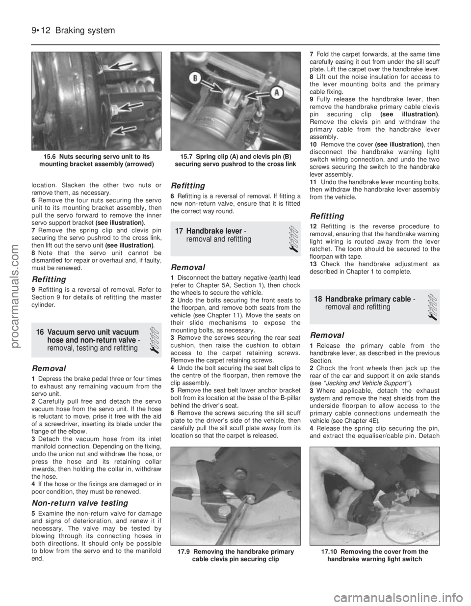
6Remove the four nuts securing the servo
unit to its mounting bracket assembly, then
pull the servo forward to remove the inner
servo support bracket (see illustration).
7 Remove the spring clip and clevis pin
securing the servo pushrod to the cross link,
then lift out the servo unit (see illustration).
8 Note that the servo unit cannot be
dismantled for repair or overhaul and, if faulty,
must be renewed.
Refitting
9 Refitting is a reversal of removal. Refer to
Section 9 for details of refitting the master
cylinder.
16 Vacuum servo unit vacuum
hose and non-return valve -
removal, testing and refitting
1
Removal
1 Depress the brake pedal three or four times
to exhaust any remaining vacuum from the
servo unit.
2 Carefully pull free and detach the servo
vacuum hose from the servo unit. If the hose
is reluctant to move, prise it free with the aid
of a screwdriver, inserting its blade under the
flange of the elbow.
3 Detach the vacuum hose from its inlet
manifold connection. Depending on the fixing,
undo the union nut and withdraw the hose, or
press the hose and its retaining collar
inwards, then holding the collar in, withdraw
the hose.
4 If the hose or the fixings are damaged or in
poor condition, they must be renewed.
Non-return valve testing
5 Examine the non-return valve for damage
and signs of deterioration, and renew it if
necessary. The valve may be tested by
blowing through its connecting hoses in
both directions. It should only be possible
to blow from the servo end to the manifold
end.
Refitting
6 Refitting is a reversal of removal. If fitting a
new non-return valve, ensure that it is fitted
the correct way round.
17 Handbrake lever -
removal and refitting
1
Removal
1 Disconnect the battery negative (earth) lead
(refer to Chapter 5A, Section 1), then chock
the wheels to secure the vehicle.
2 Undo the bolts securing the front seats to
the floorpan, and remove both seats from the
vehicle (see Chapter 11). Move the seats on
their slide mechanisms to expose the
mounting bolts, as necessary.
3 Remove the screws securing the rear seat
cushion, then raise the cushion to obtain
access to the carpet retaining screws.
Remove the carpet retaining screws.
4 Undo the bolt securing the seat belt clips to
the centre of the floorpan, then remove the
clip assembly.
5 Remove the seat belt lower anchor bracket
bolt from its location at the base of the B-pillar
behind the driver’s seat.
6 Remove the screws securing the sill scuff
plate to the driver’s side of the vehicle, then
carefully pull the sill scuff plate away from its
location so that the carpet is released. 7
Fold the carpet forwards, at the same time
carefully easing it out from under the sill scuff
plate. Lift the carpet over the handbrake lever.
8 Lift out the noise insulation for access to
the lever mounting bolts and the primary
cable fixing.
9 Fully release the handbrake lever, then
remove the handbrake primary cable clevis
pin securing clip (see illustration).
Remove the clevis pin and withdraw the
primary cable from the handbrake lever
assembly.
10 Remove the cover (see illustration), then
disconnect the handbrake warning light
switch wiring connection, and undo the two
screws securing the switch to the handbrake
lever assembly.
11 Undo the handbrake lever mounting bolts,
then withdraw the handbrake lever assembly
from the vehicle.
Refitting
12 Refitting is the reverse procedure to
removal, ensuring that the handbrake warning
light wiring is routed away from the lever
ratchet. The loom should be secured to the
floorpan with tape.
13 Check the handbrake adjustment as
described in Chapter 1 to complete.
18 Handbrake primary cable -
removal and refitting
1
Removal
1 Release the primary cable from the
handbrake lever, as described in the previous
Section.
2 Chock the front wheels then jack up the
rear of the car and support it on axle stands
(see “Jacking and Vehicle Support” ).
3 Where applicable, detach the exhaust
system and remove the heat shields from the
underside floorpan to allow access to the
primary cable connections underneath the
vehicle (see Chapter 4E).
4 Release the spring clip securing the pin,
and extract the equaliser/cable pin. Detach
9•12 Braking system
17.10 Removing the cover from the
handbrake warning light switch17.9 Removing the handbrake primary cable clevis pin securing clip
15.7 Spring clip (A) and clevis pin (B)
securing servo pushrod to the cross link15.6 Nuts securing servo unit to its
mounting bracket assembly (arrowed)
1595Ford Fiesta Remakeprocarmanuals.com
http://vnx.su
Page 202 of 296
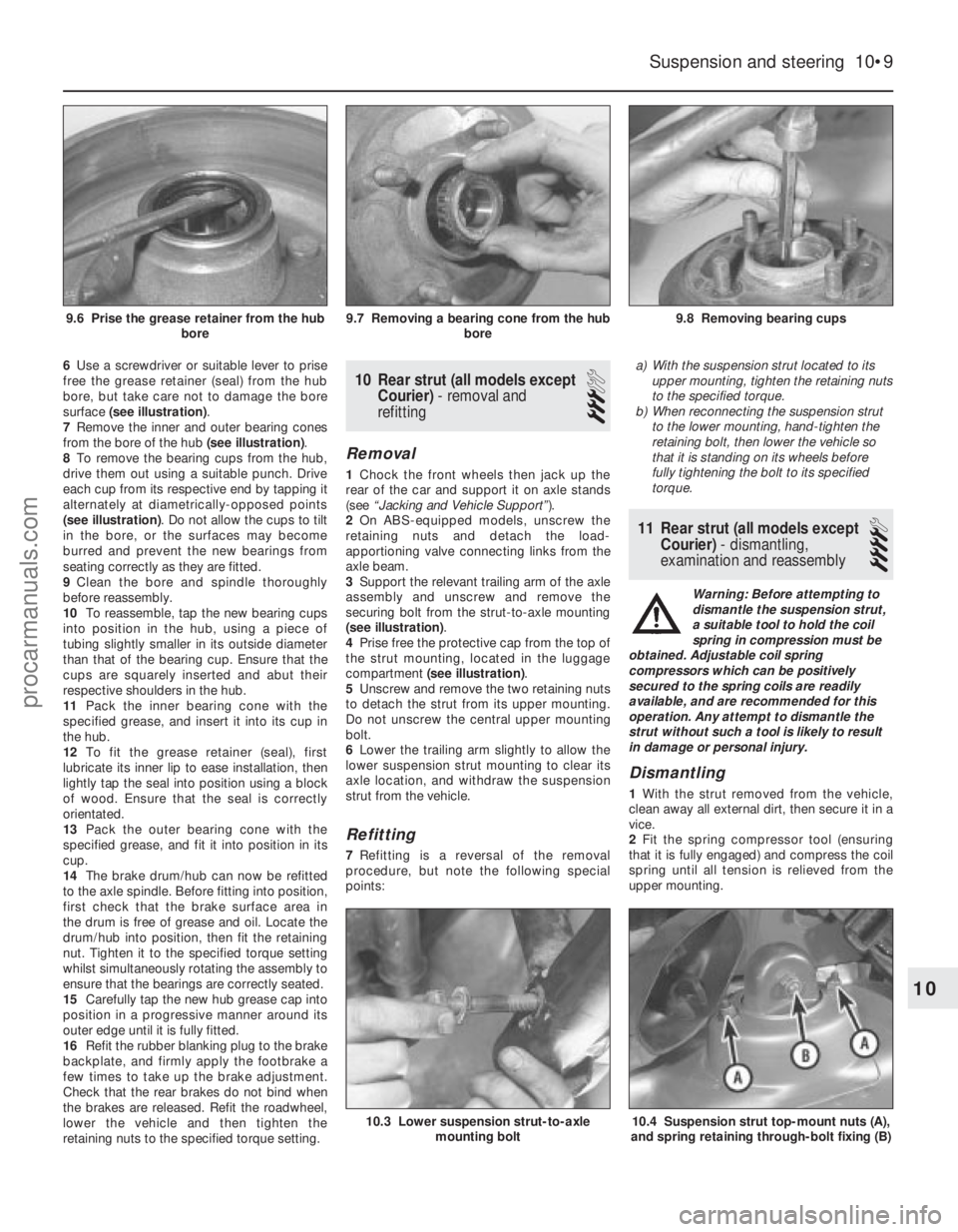
6Use a screwdriver or suitable lever to prise
free the grease retainer (seal) from the hub
bore, but take care not to damage the bore
surface (see illustration) .
7 Remove the inner and outer bearing cones
from the bore of the hub (see illustration).
8 To remove the bearing cups from the hub,
drive them out using a suitable punch. Drive
each cup from its respective end by tapping it
alternately at diametrically-opposed points
(see illustration) . Do not allow the cups to tilt
in the bore, or the surfaces may become
burred and prevent the new bearings from
seating correctly as they are fitted.
9 Clean the bore and spindle thoroughly
before reassembly.
10 To reassemble, tap the new bearing cups
into position in the hub, using a piece of
tubing slightly smaller in its outside diameter
than that of the bearing cup. Ensure that the
cups are squarely inserted and abut their
respective shoulders in the hub.
11 Pack the inner bearing cone with the
specified grease, and insert it into its cup in
the hub.
12 To fit the grease retainer (seal), first
lubricate its inner lip to ease installation, then
lightly tap the seal into position using a block
of wood. Ensure that the seal is correctly
orientated.
13 Pack the outer bearing cone with the
specified grease, and fit it into position in its
cup.
14 The brake drum/hub can now be refitted
to the axle spindle. Before fitting into position,
first check that the brake surface area in
the drum is free of grease and oil. Locate the
drum/hub into position, then fit the retaining
nut. Tighten it to the specified torque setting
whilst simultaneously rotating the assembly to
ensure that the bearings are correctly seated.
15 Carefully tap the new hub grease cap into
position in a progressive manner around its
outer edge until it is fully fitted.
16 Refit the rubber blanking plug to the brake
backplate, and firmly apply the footbrake a
few times to take up the brake adjustment.
Check that the rear brakes do not bind when
the brakes are released. Refit the roadwheel,
lower the vehicle and then tighten the
retaining nuts to the specified torque setting.10 Rear strut (all models except Courier) - removal and
refitting
3
Removal
1 Chock the front wheels then jack up the
rear of the car and support it on axle stands
(see “Jacking and Vehicle Support” ).
2 On ABS-equipped models, unscrew the
retaining nuts and detach the load-
apportioning valve connecting links from the
axle beam.
3 Support the relevant trailing arm of the axle
assembly and unscrew and remove the
securing bolt from the strut-to-axle mounting
(see illustration) .
4 Prise free the protective cap from the top of
the strut mounting, located in the luggage
compartment (see illustration) .
5 Unscrew and remove the two retaining nuts
to detach the strut from its upper mounting.
Do not unscrew the central upper mounting
bolt.
6 Lower the trailing arm slightly to allow the
lower suspension strut mounting to clear its
axle location, and withdraw the suspension
strut from the vehicle.
Refitting
7 Refitting is a reversal of the removal
procedure, but note the following special
points: a)
With the suspension strut located to its
upper mounting, tighten the retaining nuts
to the specified torque.
b) When reconnecting the suspension strut
to the lower mounting, hand-tighten the
retaining bolt, then lower the vehicle so
that it is standing on its wheels before
fully tightening the bolt to its specified
torque.
11 Rear strut (all models except
Courier) - dismantling,
examination and reassembly
4
Warning: Before attempting to
dismantle the suspension strut,
a suitable tool to hold the coil
spring in compression must be
obtained. Adjustable coil spring
compressors which can be positively
secured to the spring coils are readily
available, and are recommended for this
operation. Any attempt to dismantle the
strut without such a tool is likely to result
in damage or personal injury.
Dismantling
1 With the strut removed from the vehicle,
clean away all external dirt, then secure it in a
vice.
2 Fit the spring compressor tool (ensuring
that it is fully engaged) and compress the coil
spring until all tension is relieved from the
upper mounting.
Suspension and steering 10•9
9.8 Removing bearing cups9.7 Removing a bearing cone from the hub bore9.6 Prise the grease retainer from the hubbore
10.4 Suspension strut top-mount nuts (A),
and spring retaining through-bolt fixing (B)10.3 Lower suspension strut-to-axle mounting bolt
10
1595Ford Fiesta Remakeprocarmanuals.com
http://vnx.su
Page 243 of 296
8Refitting is a reversal of the removal
procedure.
Front direction indicator side
repeater
9 Remove the appropriate front wheel arch
liner as described in Chapter 11.
10 Remove the appropriate sill scuff plate as
described in Chapter 11, and release the clip
securing the insulation to the panel forward of
the lower A-pillar.
11 Disconnect the supply lead connector and
the earth lead, then release their grommet
from its panel location.
12 From outside the vehicle, twist the light
assembly to release it, then withdraw it and its
leads.
13 Refitting is a reversal of the removal
procedure, ensuring that the grommet is
seated correctly in its panel location.
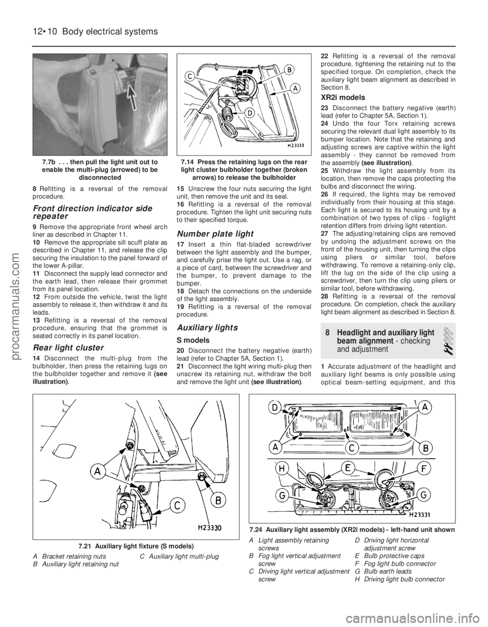
Rear light cluster
14 Disconnect the multi-plug from the
bulbholder, then press the retaining lugs on
the bulbholder together and remove it (see
illustration) . 15
Unscrew the four nuts securing the light
unit, then remove the unit and its seal.
16 Refitting is a reversal of the removal
procedure. Tighten the light unit securing nuts
to their specified torque.
Number plate light
17 Insert a thin flat-bladed screwdriver
between the light assembly and the bumper,
and carefully prise the light out. Use a rag, or
a piece of card, between the screwdriver and
the bumper, to prevent damage to the
bumper.
18 Detach the connections on the underside
of the light assembly.
19 Refitting is a reversal of the removal
procedure.
Auxiliary lights
S models
20 Disconnect the battery negative (earth)
lead (refer to Chapter 5A, Section 1).
21 Disconnect the light wiring multi-plug then
unscrew its retaining nut, withdraw the bolt
and remove the light unit (see illustration).22
Refitting is a reversal of the removal
procedure, tightening the retaining nut to the
specified torque. On completion, check the
auxiliary light beam alignment as described in
Section 8.
XR2i models
23 Disconnect the battery negative (earth)
lead (refer to Chapter 5A, Section 1).
24 Undo the four Torx retaining screws
securing the relevant dual light assembly to its
bumper location. Note that the retaining and
adjusting screws are captive within the light
assembly - they cannot be removed from
the assembly (see illustration) .
25 Withdraw the light assembly from its
location, then remove the caps protecting the
bulbs and disconnect the wiring.
26 If required, the lights may be removed
individually from their housing at this stage.
Each light is secured to its housing unit by a
combination of two types of clips - foglight
retention differs from driving light retention.
27 The adjusting/retaining clips are removed
by undoing the adjustment screws on the
front of the housing unit, then turning the clips
using pliers or similar tool, before
withdrawing. To remove a retaining-only clip,
lift the lug on the side of the clip using a
screwdriver, then turn the clip using pliers or
similar tool, before withdrawing.
28 Refitting is a reversal of the removal
procedure. On completion, check the auxiliary
light beam alignment as described in Section 8.
8 Headlight and auxiliary light
beam alignment - checking
and adjustment
2
1 Accurate adjustment of the headlight and
auxiliary light beams is only possible using
optical beam-setting equipment, and this
12•10 Body electrical systems
7.24 Auxiliary light assembly (XR2i models) - left-hand unit shown
A Light assembly retaining screws
B Fog light vertical adjustment screw
C Driving light vertical adjustment screw D Driving light horizontal
adjustment screw
E Bulb protective caps
F Fog light bulb connector
G Bulb earth leads
H Driving light bulb connector
7.21 Auxiliary light fixture (S models)
A Bracket retaining nuts C Auxiliary light multi-plug
B Auxiliary light retaining nut
7.14 Press the retaining lugs on the rear
light cluster bulbholder together (broken arrows) to release the bulbholder7.7b . . . then pull the light unit out to
enable the multi-plug (arrowed) to be disconnected
1595Ford Fiesta Remakeprocarmanuals.com
http://vnx.su
Page 244 of 296
work should therefore be carried out by a
Ford dealer or service station with the
necessary facilities.
2Temporary adjustment can be made when
the headlight has been removed and refitted,
or to compensate for normal adjustment
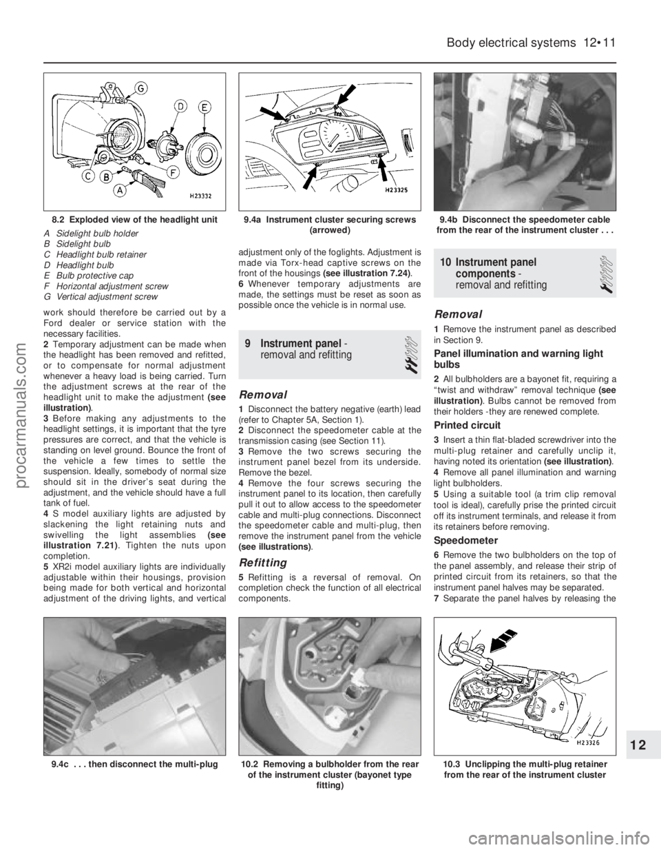
whenever a heavy load is being carried. Turn
the adjustment screws at the rear of the
headlight unit to make the adjustment (see
illustration) .
3 Before making any adjustments to the
headlight settings, it is important that the tyre
pressures are correct, and that the vehicle is
standing on level ground. Bounce the front of
the vehicle a few times to settle the
suspension. Ideally, somebody of normal size
should sit in the driver’s seat during the
adjustment, and the vehicle should have a full
tank of fuel.
4 S model auxiliary lights are adjusted by
slackening the light retaining nuts and
swivelling the light assemblies (see
illustration 7.21) . Tighten the nuts upon
completion.
5 XR2i model auxiliary lights are individually
adjustable within their housings, provision
being made for both vertical and horizontal
adjustment of the driving lights, and vertical adjustment only of the foglights. Adjustment is
made via Torx-head captive screws on the
front of the housings
(see illustration 7.24) .
6 Whenever temporary adjustments are
made, the settings must be reset as soon as
possible once the vehicle is in normal use.
9 Instrument panel -
removal and refitting
2
Removal
1 Disconnect the battery negative (earth) lead
(refer to Chapter 5A, Section 1).
2 Disconnect the speedometer cable at the
transmission casing (see Section 11).
3 Remove the two screws securing the
instrument panel bezel from its underside.
Remove the bezel.
4 Remove the four screws securing the
instrument panel to its location, then carefully
pull it out to allow access to the speedometer
cable and multi-plug connections. Disconnect
the speedometer cable and multi-plug, then
remove the instrument panel from the vehicle
(see illustrations) .
Refitting
5Refitting is a reversal of removal. On
completion check the function of all electrical
components.
10 Instrument panel
components -
removal and refitting
1
Removal
1 Remove the instrument panel as described
in Section 9.
Panel illumination and warning light
bulbs
2 All bulbholders are a bayonet fit, requiring a
“twist and withdraw” removal technique (see
illustration) . Bulbs cannot be removed from
their holders -they are renewed complete.
Printed circuit
3 Insert a thin flat-bladed screwdriver into the
multi-plug retainer and carefully unclip it,
having noted its orientation (see illustration).
4 Remove all panel illumination and warning
light bulbholders.
5 Using a suitable tool (a trim clip removal
tool is ideal), carefully prise the printed circuit
off its instrument terminals, and release it from
its retainers before removing.
Speedometer
6 Remove the two bulbholders on the top of
the panel assembly, and release their strip of
printed circuit from its retainers, so that the
instrument panel halves may be separated.
7 Separate the panel halves by releasing the
Body electrical systems 12•11
9.4b Disconnect the speedometer cable
from the rear of the instrument cluster . . .9.4a Instrument cluster securing screws (arrowed)8.2 Exploded view of the headlight unit
A Sidelight bulb holder
B Sidelight bulb
C Headlight bulb retainer
D Headlight bulb
E Bulb protective cap
F Horizontal adjustment screw
G Vertical adjustment screw
10.3 Unclipping the multi-plug retainer from the rear of the instrument cluster10.2 Removing a bulbholder from the rear of the instrument cluster (bayonet type
fitting)9.4c . . . then disconnect the multi-plug
12
1595Ford Fiesta Remakeprocarmanuals.com
http://vnx.su
Page 276 of 296
1595 Ford Fiesta Remake
REF•10MOT test checks
This is a guide to getting your vehicle through the MOT test.
Obviously it will not be possible to examine the vehicle to the same
standar d as the professional MOT tester. However, working through
the following checks will enable you to identify any problem areas
befor e submitting the vehicle for the test.
Wher e a testable component is in borderline condition, the tester
has discretion in deciding whether to pass or fail it. The basis of such
discr etion is whether the tester would be happy for a close relative or
friend to use the vehicle with the component in that condition. If the
vehicle presented is clean and evidently well cared for, the tester may
be more inclined to pass a borderline component than if the vehicle is
scruffy and apparently neglected.
It has only been possible to summarise the test requirements her e,
based on the regulations in force at the time of printing. Test standards ar e becoming increasingly stringent, although there are some
exemptions for older vehicles. For full details obtain a copy of the Hay\
nes
publication Pass the MOT! (available from stockists of Haynes manuals).
An assistant will be needed to help carry out some of these checks.
The checks have been sub-divided into four categories, as follows:
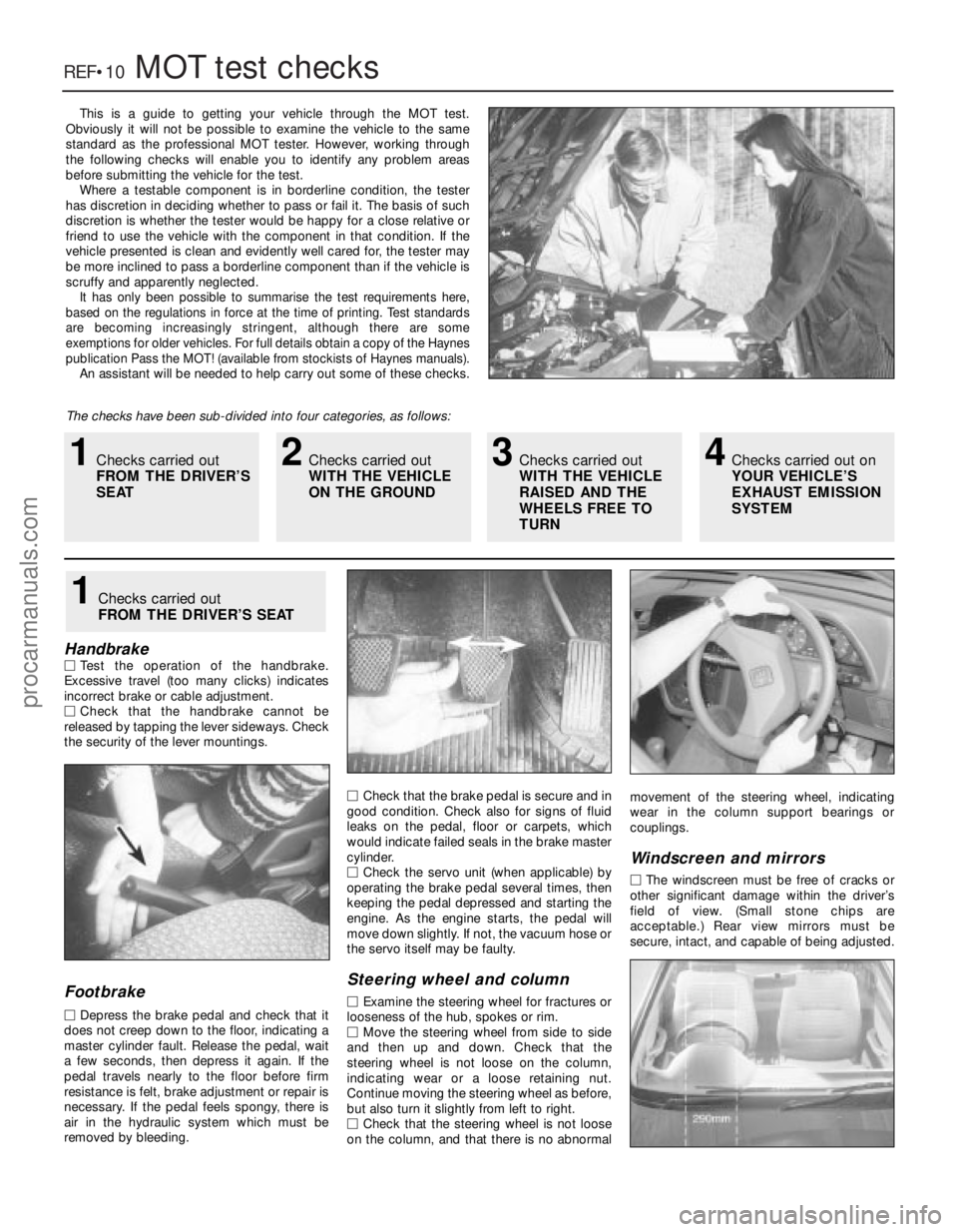
HandbrakeM Test the operation of the handbrake.
Excessive travel (too many clicks) indicates
incorr ect brake or cable adjustment.
M Check that the handbrake cannot be
r eleased by tapping the lever sideways. Check
the security of the lever mountings.
Footbrake
M Depr ess the brake pedal and check that it
does not creep down to the floor, indicating a master cylinder fault. Release the pedal, wait
a few seconds, then depress it again. If the
pedal travels nearly to the floor before firm
r esistance is felt, brake adjustment or repair is
necessary . If the pedal feels spongy, there is
air in the hydraulic system which must be
r emoved by bleeding. M
Check that the brake pedal is secure and in
good condition. Check also for signs of fluid
leaks on the pedal, floor or carpets, which
would indicate failed seals in the brake master
cylinder.
M Check the servo unit (when applicable) by
operating the brake pedal several times, then
keeping the pedal depressed and starting the
engine. As the engine starts, the pedal will
move down slightly. If not, the vacuum hose or
the servo itself may be faulty.
Steering wheel and column
M Examine the steering wheel for fractures or
looseness of the hub, spokes or rim.
M Move the steering wheel from side to side
and then up and down. Check that the
steering wheel is not loose on the column,
indicating wear or a loose retaining nut.
Continue moving the steering wheel as before,
but also turn it slightly from left to right.
M Check that the steering wheel is not loose
on the column, and that there is no abnormal movement of the steering wheel, indicating
wear in the column support bearings or
couplings.
W
indscreen and mirrors
M The windscreen must be free of cracks or
other significant damage within the driver’s
field of view. (Small stone chips are
acceptable.) Rear view mirrors must be
secur e, intact, and capable of being adjusted.
1Checks carried out
FROM THE DRIVER’S SEAT
1Checks carried out
FROM THE DRIVER’S
SEAT2Checks carried out
WITH THE VEHICLE
ON THE GROUND3Checks carried out
WITH THE VEHICLE
RAISED AND THE
WHEELS FREE TO
TURN4Checks carried out on
YOUR VEHICLE’S
EXHAUST EMISSION
SYSTEM
procarmanuals.com
http://vnx.su