oil type FORD FIESTA 1989 Service Owner's Manual
[x] Cancel search | Manufacturer: FORD, Model Year: 1989, Model line: FIESTA, Model: FORD FIESTA 1989Pages: 296, PDF Size: 10.65 MB
Page 51 of 296
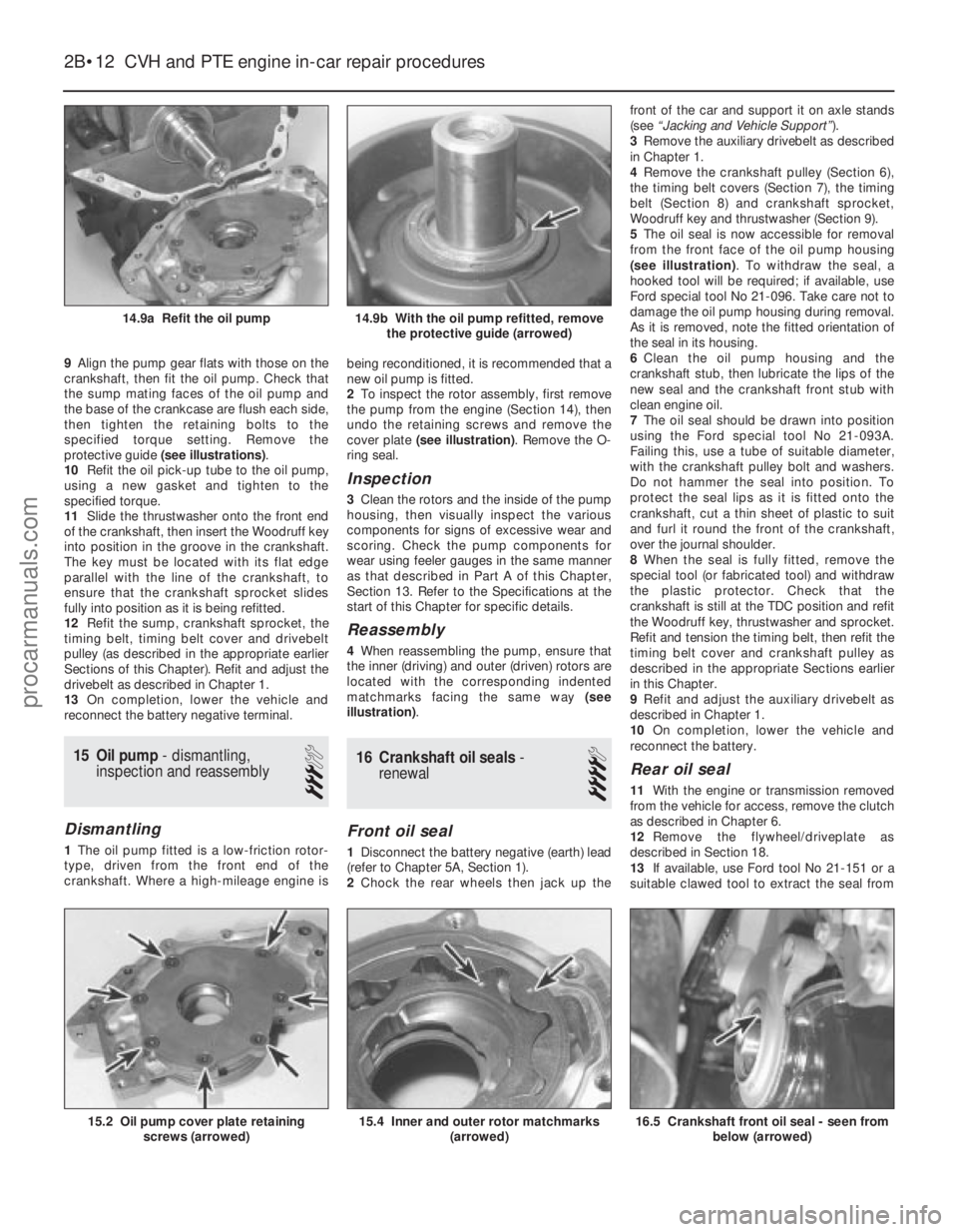
9Align the pump gear flats with those on the
crankshaft, then fit the oil pump. Check that
the sump mating faces of the oil pump and
the base of the crankcase are flush each side,
then tighten the retaining bolts to the
specified torque setting. Remove the
protective guide (see illustrations) .
10 Refit the oil pick-up tube to the oil pump,
using a new gasket and tighten to the
specified torque.
11 Slide the thrustwasher onto the front end
of the crankshaft, then insert the Woodruff key
into position in the groove in the crankshaft.
The key must be located with its flat edge
parallel with the line of the crankshaft, to
ensure that the crankshaft sprocket slides
fully into position as it is being refitted.
12 Refit the sump, crankshaft sprocket, the
timing belt, timing belt cover and drivebelt
pulley (as described in the appropriate earlier
Sections of this Chapter). Refit and adjust the
drivebelt as described in Chapter 1.
13 On completion, lower the vehicle and
reconnect the battery negative terminal.
15 Oil pump - dismantling,
inspection and reassembly
3
Dismantling
1 The oil pump fitted is a low-friction rotor-
type, driven from the front end of the
crankshaft. Where a high-mileage engine is being reconditioned, it is recommended that a
new oil pump is fitted.
2
To inspect the rotor assembly, first remove
the pump from the engine (Section 14), then
undo the retaining screws and remove the
cover plate (see illustration) . Remove the O-
ring seal.
Inspection
3 Clean the rotors and the inside of the pump
housing, then visually inspect the various
components for signs of excessive wear and
scoring. Check the pump components for
wear using feeler gauges in the same manner
as that described in Part A of this Chapter,
Section 13. Refer to the Specifications at the
start of this Chapter for specific details.
Reassembly
4 When reassembling the pump, ensure that
the inner (driving) and outer (driven) rotors are
located with the corresponding indented
matchmarks facing the same way (see
illustration) .
16Crankshaft oil seals -
renewal
4
Front oil seal
1 Disconnect the battery negative (earth) lead
(refer to Chapter 5A, Section 1).
2 Chock the rear wheels then jack up the front of the car and support it on axle stands
(see
“Jacking and Vehicle Support” ).
3 Remove the auxiliary drivebelt as described
in Chapter 1.
4 Remove the crankshaft pulley (Section 6),
the timing belt covers (Section 7), the timing
belt (Section 8) and crankshaft sprocket,
Woodruff key and thrustwasher (Section 9).
5 The oil seal is now accessible for removal
from the front face of the oil pump housing
(see illustration) . To withdraw the seal, a
hooked tool will be required; if available, use
Ford special tool No 21-096. Take care not to
damage the oil pump housing during removal.
As it is removed, note the fitted orientation of
the seal in its housing.
6 Clean the oil pump housing and the
crankshaft stub, then lubricate the lips of the
new seal and the crankshaft front stub with
clean engine oil.
7 The oil seal should be drawn into position
using the Ford special tool No 21-093A.
Failing this, use a tube of suitable diameter,
with the crankshaft pulley bolt and washers.
Do not hammer the seal into position. To
protect the seal lips as it is fitted onto the
crankshaft, cut a thin sheet of plastic to suit
and furl it round the front of the crankshaft,
over the journal shoulder.
8 When the seal is fully fitted, remove the
special tool (or fabricated tool) and withdraw
the plastic protector. Check that the
crankshaft is still at the TDC position and refit
the Woodruff key, thrustwasher and sprocket.
Refit and tension the timing belt, then refit the
timing belt cover and crankshaft pulley as
described in the appropriate Sections earlier
in this Chapter.
9 Refit and adjust the auxiliary drivebelt as
described in Chapter 1.
10 On completion, lower the vehicle and
reconnect the battery.
Rear oil seal
11 With the engine or transmission removed
from the vehicle for access, remove the clutch
as described in Chapter 6.
12 Remove the flywheel/driveplate as
described in Section 18.
13 If available, use Ford tool No 21-151 or a
suitable clawed tool to extract the seal from
2B•12 CVH and PTE engine in-car repair procedures
16.5 Crankshaft front oil seal - seen from
below (arrowed)15.4 Inner and outer rotor matchmarks (arrowed)15.2 Oil pump cover plate retainingscrews (arrowed)
14.9b With the oil pump refitted, removethe protective guide (arrowed)14.9a Refit the oil pump
1595Ford Fiesta Remakeprocarmanuals.com
http://vnx.su
Page 54 of 296

2C
1595Ford Fiesta Remake
General
Engine type . . . . . . . . . . . . . . . . . . . . . . . . . . . . . . . . . . . .\
. . . . . . . . . . . Four-cylinder, in-line, double overhead camshafts
Engine code:1.6 litre models . . . . . . . . . . . . . . . . . . . . . . . . . . . . . . . . . . . .\
. . . . . . L1G
1.8 litre models . . . . . . . . . . . . . . . . . . . . . . . . . . . . . . . . . . . .\
. . . . . . RDB or RQC
Capacity:
1.6 litre models . . . . . . . . . . . . . . . . . . . . . . . . . . . . . . . . . . . .\
. . . . . . 1597 cc
1.8 litre models . . . . . . . . . . . . . . . . . . . . . . . . . . . . . . . . . . . .\
. . . . . . 1796 cc
Bore:
1.6 litre models . . . . . . . . . . . . . . . . . . . . . . . . . . . . . . . . . . . .\
. . . . . . 76.0 mm
1.8 litre models . . . . . . . . . . . . . . . . . . . . . . . . . . . . . . . . . . . .\
. . . . . . 80.6 mm
Stroke - all models . . . . . . . . . . . . . . . . . . . . . . . . . . . . . . . . . . . .\
. . . . . 88.0 mm
Compression ratio: 1.6 litre models . . . . . . . . . . . . . . . . . . . . . . . . . . . . . . . . . . . .\
. . . . . . 10.3:1
1.8 litre models . . . . . . . . . . . . . . . . . . . . . . . . . . . . . . . . . . . .\
. . . . . . 10.0:1
Firing order . . . . . . . . . . . . . . . . . . . . . . . . . . . . . . . . . . . .\
. . . . . . . . . . . 1-3-4-2 (No 1 cylinder at timing belt end)
Direction of crankshaft rotation . . . . . . . . . . . . . . . . . . . . . . . . . . . . . . . Clockwise (seen from right-hand side of vehicle)
Cylinder head
Hydraulic tappet bore inside diameter . . . . . . . . . . . . . . . . . . . . . . . . . . 28.395 to 28.425 mm
Camshafts and hydraulic tappets
Camshaft bearing journal diameter . . . . . . . . . . . . . . . . . . . . . . . . . . . . 25.960 to 25.980 mm
Camshaft bearing journal-to-cylinder head running clearance . . . . . . . 0.020 to 0.070 mm
Camshaft endfloat . . . . . . . . . . . . . . . . . . . . . . . . . . . . . . . . . . . .\
. . . . . 0.080 to 0.220 mm
Lubrication
Engine oil type/specification . . . . . . . . . . . . . . . . . . . . . . . . . . . . . . . . . . See “Lubricants, fluids and tyre pressures”
Engine oil capacity . . . . . . . . . . . . . . . . . . . . . . . . . . . . . . . . . . . .\
. . . . . See “Lubricants, fluids and tyre pressures”
Oil pressure: Idling . . . . . . . . . . . . . . . . . . . . . . . . . . . . . . . . . . . .\
. . . . . . . . . . . . . . 1.3 to 2.5 bar
At 4000 rpm . . . . . . . . . . . . . . . . . . . . . . . . . . . . . . . . . . . .\
. . . . . . . . 3.7 to 5.5 bars
Oil pump clearances . . . . . . . . . . . . . . . . . . . . . . . . . . . . . . . . . . . .\
. . . . Not specified
Chapter 2 Part C:
Zetec engine in-car repair procedures
Auxiliary drivebelt check and renewal . . . . . . . . . . . . . . .See Chapter 1
Camshaft oil seals - renewal . . . . . . . . . . . . . . . . . . . . . . . . . . . . . . . 10
Camshafts and hydraulic tappets - removal, inspection and refitting . . . . . . . . . . . . . . . . . . . . . . . . . . . . . . . . . . . .\
. . . . . . 11
Compression test - description and interpretation . . . . . . . . . . . . . . 2
Crankshaft oil seals - renewal . . . . . . . . . . . . . . . . . . . . . . . . . . . . . . 15
Crankshaft pulley - removal and refitting . . . . . . . . . . . . . . . . . . . . . 6
Cylinder head - removal and refitting . . . . . . . . . . . . . . . . . . . . . . . . 12
Cylinder head cover - removal and refitting . . . . . . . . . . . . . . . . . . . 4
Engine oil and filter renewal . . . . . . . . . . . . . . . . . . . . . . .See Chapter 1
Engine oil level check . . . . . . . . . . . . . . . . . . . . . . . . . “Weekly Checks”Engine/transmission mountings - inspection and renewal . . . . . . . . 16
Flywheel/driveplate - removal, inspection and refitting . . . . . . . . . . 17
General information . . . . . . . . . . . . . . . . . . . . . . . . . . . . . . . . . . . .\
. . 1
Oil pump - removal, inspection and refitting . . . . . . . . . . . . . . . . . . . 14
Sump - removal and refitting . . . . . . . . . . . . . . . . . . . . . . . . . . . . . . . 13
Timing belt - removal, refitting and adjustment . . . . . . . . . . . . . . . . 8
Timing belt covers - removal and refitting . . . . . . . . . . . . . . . . . . . . . 7
Timing belt tensioner and sprockets - removal, inspection
and refitting . . . . . . . . . . . . . . . . . . . . . . . . . . . . . . . . . . . .\
. . . . . . 9
Top Dead Centre (TDC) for No 1 piston - locating . . . . . . . . . . . . . . 3
Valve clearances - general information . . . . . . . . . . . . . . . . . . . . . . . 5
2C•1
Specifications Contents
Easy, suitable for
novice with little
experience Fairly easy,
suitable
for beginner with
some experience Fairly difficult,
suitable for competent
DIY mechanic
Difficult,
suitable for
experienced DIY
mechanic Very difficult,
suitable for expert DIY
or professional
Degrees of difficulty
54321
procarmanuals.com
http://vnx.su
Page 55 of 296

Torque wrench settingsNmlbf ft
Cylinder head cover bolts: Stage 1 . . . . . . . . . . . . . . . . . . . . . . . . . . . . . . . . . . . .\
. . . . . . . . . . . . 2 1.5
Stage 2 . . . . . . . . . . . . . . . . . . . . . . . . . . . . . . . . . . . .\
. . . . . . . . . . . . 7 5
Camshaft sprocket bolts . . . . . . . . . . . . . . . . . . . . . . . . . . . . . . . . . . . .\
6850
Camshaft bearing cap bolts: Stage 1 . . . . . . . . . . . . . . . . . . . . . . . . . . . . . . . . . . . .\
. . . . . . . . . . . . 9 7
Stage 2 . . . . . . . . . . . . . . . . . . . . . . . . . . . . . . . . . . . .\
. . . . . . . . . . . . 1914
Cylinder head bolts: Stage 1 . . . . . . . . . . . . . . . . . . . . . . . . . . . . . . . . . . . .\
. . . . . . . . . . . . 2418
Stage 2 . . . . . . . . . . . . . . . . . . . . . . . . . . . . . . . . . . . .\
. . . . . . . . . . . . 4533
Stage 3 . . . . . . . . . . . . . . . . . . . . . . . . . . . . . . . . . . . .\
. . . . . . . . . . . . Angle-tighten a further 105º
Timing belt cover fasteners: Upper-to-middle (outer) cover bolts . . . . . . . . . . . . . . . . . . . . . . . . . . 4 3
Cover-to-cylinder head or block bolts . . . . . . . . . . . . . . . . . . . . . . . . 7 5
Cover studs-to-cylinder head or block . . . . . . . . . . . . . . . . . . . . . . . . 9 7
Timing belt tensioner bolt . . . . . . . . . . . . . . . . . . . . . . . . . . . . . . . . . . . .\
3828
Timing belt tensioner backplate locating peg . . . . . . . . . . . . . . . . . . . . . 9 7
Timing belt tensioner spring retaining pin . . . . . . . . . . . . . . . . . . . . . . . 9 7
Timing belt guide pulley bolts . . . . . . . . . . . . . . . . . . . . . . . . . . . . . . . . . 3828
Water pump pulley bolts . . . . . . . . . . . . . . . . . . . . . . . . . . . . . . . . . . . .\
. 9 7
Auxiliary drivebelt idler pulley . . . . . . . . . . . . . . . . . . . . . . . . . . . . . . . . . 4735
Front engine lifting eye bolt . . . . . . . . . . . . . . . . . . . . . . . . . . . . . . . . . . 1612
Exhaust manifold heat shield bolts: Shield-to-cylinder head . . . . . . . . . . . . . . . . . . . . . . . . . . . . . . . . . . . 7 5
Shield/dipstick tube . . . . . . . . . . . . . . . . . . . . . . . . . . . . . . . . . . . .\
. . 9 7
Shield/coolant pipe-to-manifold . . . . . . . . . . . . . . . . . . . . . . . . . . . . . 2317
Crankshaft pulley bolt . . . . . . . . . . . . . . . . . . . . . . . . . . . . . . . . . . . .\
. . . 115 85
Oil pump-to-cylinder block bolts . . . . . . . . . . . . . . . . . . . . . . . . . . . . . . 107
Oil pick-up pipe-to-pump screws . . . . . . . . . . . . . . . . . . . . . . . . . . . . . . 107
Oil baffle/pump pick-up pipe nuts . . . . . . . . . . . . . . . . . . . . . . . . . . . . . 1914
Oil filter adapter-to-pump . . . . . . . . . . . . . . . . . . . . . . . . . . . . . . . . . . . .\
2216
Oil pressure warning light switch . . . . . . . . . . . . . . . . . . . . . . . . . . . . . . 2720
Sump bolts . . . . . . . . . . . . . . . . . . . . . . . . . . . . . . . . . . . .\
. . . . . . . . . . . 2015
Coolant pipe-to-sump bolt . . . . . . . . . . . . . . . . . . . . . . . . . . . . . . . . . . . 9 7
Flywheel/driveplate bolts . . . . . . . . . . . . . . . . . . . . . . . . . . . . . . . . . . . .\
110 81
Crankshaft left-hand oil seal carrier bolts . . . . . . . . . . . . . . . . . . . . . . . . 2216
Engine mountings: Engine front right-hand mounting:Alternator mounting bracket-to-cylinder block bolts . . . . . . . . . . . 41 to 58 30 to 43
Mounting bracket-to-alternator mounting bracket bolts . . . . . . . . Not available Not available
Mounting through-bolt . . . . . . . . . . . . . . . . . . . . . . . . . . . . . . . . . . Not available Not available
Outer bracket-to-mounting bolts . . . . . . . . . . . . . . . . . . . . . . . . . . 58 to 79 43 to 58
Inner bracket-to-body bolts . . . . . . . . . . . . . . . . . . . . . . . . . . . . . . 58 to 79 43 to 58
Outer bracket-to-body bolts . . . . . . . . . . . . . . . . . . . . . . . . . . . . . . 58 to 79 43 to 58
Engine rear right-hand mounting: . . . . . . . . . . . . . . . . . . . . . . . . . . . . Bracket-to-cylinder block bolts . . . . . . . . . . . . . . . . . . . . . . . . . . . 76 to 104 56 to 77
Mounting-to-(cylinder block) bracket bolts . . . . . . . . . . . . . . . . . . . 71 to 98 52 to 72
Mounting-to-body bolt and nut . . . . . . . . . . . . . . . . . . . . . . . . . . . . 102 to 138 75 to 102
Transmission mounting fasteners . . . . . . . . . . . . . . . . . . . . . . . . . . . . Refer to Chapter 7A or 7B
Note: Refer to Part D of this Chapter for remaining torque wrench settings.
2C•2 Zetec engine in-car repair procedures
1595Ford Fiesta Remake
1 General information
How to use this Chapter
This Part of Chapter 2 is devoted to repair
procedures possible while the engine is still
installed in the vehicle, and includes only the
Specifications relevant to those procedures.
Similar information concerning the 1.3 litre
HCS engines, and the 1.4 and 1.6 litre CVH
and PTE engines, will be found in Parts A
and B of this Chapter respectively. Since these procedures are based on the
assumption that the engine is installed in the
vehicle, if the engine has been removed from
the vehicle and mounted on a stand, some
of the preliminary dismantling steps outlined
will not apply.
Information concerning engine/transmission
removal and refitting, and engine overhaul, can
be found in Part D of this Chapter, which also
includes the Specifications relevant to those
procedures.
Engine description
The Zetec engine, (formerly Zeta), is of
sixteen-valve, double overhead camshaft (DOHC), four-cylinder, in-line type, mounted
transversely at the front of the vehicle, with
the transmission on its left-hand end.
Apart from the plastic timing belt covers
and the cast-iron cylinder block/crankcase, all
major engine castings are of aluminium alloy. The crankshaft runs in five main bearings,
the centre main bearing’s upper half
incorporating thrustwashers to control
crankshaft endfloat. The connecting rods
rotate on horizontally-split bearing shells at
their big-ends. The pistons are attached to the
connecting rods by gudgeon pins which are
an interference fit in the connecting rod small-
end eyes. The aluminium alloy pistons are
procarmanuals.com
http://vnx.su
Page 56 of 296
fitted with three piston rings: two
compression rings and an oil control ring.
After manufacture, the cylinder bores and
piston skirts are measured and classified into
three grades, which must be carefully
matched together, to ensure the correct
piston/cylinder clearance; no oversizes are
available to permit reboring.The inlet and exhaust valves are each
closed by coil springs; they operate in guides
which are shrink-fitted into the cylinder head,
as are the valve seat inserts. Both camshafts are driven by the same
toothed timing belt, each operating eight
valves via self-adjusting hydraulic tappets,
thus eliminating the need for routine checking
and adjustment of the valve clearances. Each
camshaft rotates in five bearings that are line-
bored directly in the cylinder head and the
(bolted-on) bearing caps; this means that the
bearing caps are not available separately from
the cylinder head, and must not be
interchanged with caps from another engine. The water pump is bolted to the right-hand
end of the cylinder block, inboard of the
timing belt, and is driven with the power
steering pump and alternator by a flat
“polyvee”-type auxiliary drivebelt from the
crankshaft pulley.
When working on this engine, note that
Torx-type (both male and female heads) and
hexagon socket (Allen head) fasteners are
widely used; a good selection of bits, with the
necessary adapters, will be required, so that
these can be unscrewed without damage and,
on reassembly, tightened to the torque
wrench settings specified. Lubrication is by means of an eccentric-
rotor trochoidal pump, which is mounted on
the crankshaft right-hand end, and draws oil
through a strainer located in the sump. The
pump forces oil through an externally-
mounted full-flow cartridge-type filter - on
some versions of the engine, an oil cooler is
fitted to the oil filter mounting, so that clean oil
entering the engine’s galleries is cooled by the
main engine cooling system.
Repair operations possible with
the engine in the car
The following work can be carried out with
the engine in the car:
a) Compression pressure - testing.
b) Cylinder head cover - removal and
refitting.
c) Timing belt covers - removal and refitting.
d) Timing belt - renewal.
e) Timing belt tensioner and sprockets - removal and refitting.
f) Camshaft oil seals - renewal.
g) Camshafts and hydraulic tappets - removal and refitting.
h) Cylinder head - removal and refitting.
i) Cylinder head and pistons - decarbonising.
j) Sump - removal and refitting.
k) Crankshaft oil seals - renewal.
l) Oil pump - removal and refitting. m)
Flywheel/driveplate - removal and
refitting.
n) Engine/transmission mountings - removal and refitting.
Note: It is possible to remove the pistons and
connecting rods (after removing the cylinder
head and sump) without removing the engine.
However, this is not recommended. Work of
this nature is more easily and thoroughly
completed with the engine on the bench, as
described in Chapter 2D.
2 Compression test -
description and interpretation
2
Refer to Section 2 in Part A of this Chapter.
3 Top Dead Centre (TDC) for No 1 piston - locating
2
1Top dead centre (TDC) is the highest point
of the cylinder that each piston reaches as the
crankshaft turns. Each piston reaches its TDC
position at the end of its compression stroke,
and then again at the end of its exhaust
stroke. For the purpose of engine timing, TDC
on the compression stroke for No 1 piston is
used. No 1 cylinder is at the timing belt end of
the engine. Proceed as follows.
2 Disconnect the battery negative (earth) lead
(refer to Chapter 5A, Section 1).
3 Chock the rear wheels then jack up the
front of the car and support it on axle stands
(see “Jacking and Vehicle Support” ). Remove
the right-hand roadwheel.
4 Remove the auxiliary drivebelt cover (see
Chapter 1) to expose the crankshaft pulley
and timing marks.
5 Fit a spanner onto the crankshaft pulley
bolt, and turn the crankshaft in its normal
direction of rotation (clockwise, viewed from
the pulley end). 6
Note the two pairs of notches in the inner
and outer rims of the crankshaft pulley. In the
normal direction of crankshaft rotation the first
pair of notches are irrelevant to the vehicles
covered in this manual, while the second pair
indicate TDC when aligned with the rear edge
of the raised mark on the sump. Rotate the
crankshaft clockwise until the second pair of
notches align with the edge of the sump mark;
use a straight edge extended out from the
sump if greater accuracy is required (see
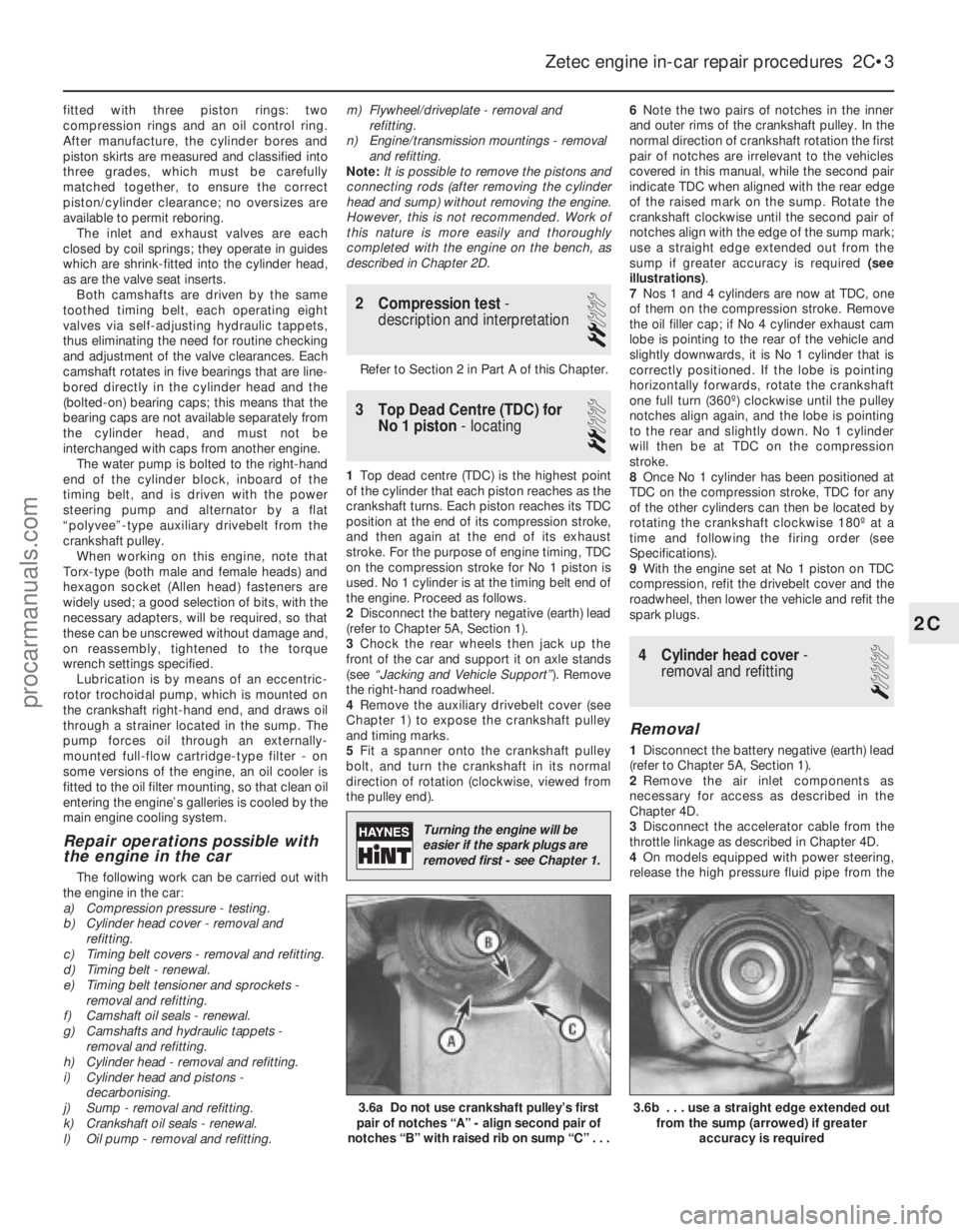
illustrations) .
7 Nos 1 and 4 cylinders are now at TDC, one
of them on the compression stroke. Remove
the oil filler cap; if No 4 cylinder exhaust cam
lobe is pointing to the rear of the vehicle and
slightly downwards, it is No 1 cylinder that is
correctly positioned. If the lobe is pointing
horizontally forwards, rotate the crankshaft
one full turn (360º) clockwise until the pulley
notches align again, and the lobe is pointing
to the rear and slightly down. No 1 cylinder
will then be at TDC on the compression
stroke.
8 Once No 1 cylinder has been positioned at
TDC on the compression stroke, TDC for any
of the other cylinders can then be located by
rotating the crankshaft clockwise 180º at a
time and following the firing order (see
Specifications).
9 With the engine set at No 1 piston on TDC
compression, refit the drivebelt cover and the
roadwheel, then lower the vehicle and refit the
spark plugs.
4 Cylinder head cover -
removal and refitting
1
Removal
1 Disconnect the battery negative (earth) lead
(refer to Chapter 5A, Section 1).
2 Remove the air inlet components as
necessary for access as described in the
Chapter 4D.
3 Disconnect the accelerator cable from the
throttle linkage as described in Chapter 4D.
4 On models equipped with power steering,
release the high pressure fluid pipe from the
Zetec engine in-car repair procedures 2C•3
3.6b . . . use a straight edge extended out from the sump (arrowed) if greater
accuracy is required3.6a Do not use crankshaft pulley’s first
pair of notches “A” - align second pair of
notches “B” with raised rib on sump “C” . . .
2C
1595Ford Fiesta Remake
Turning the engine will be
easier if the spark plugs are
removed first - see Chapter 1.
procarmanuals.com
http://vnx.su
Page 79 of 296
25Unscrew the retaining bolt, and detach
the shift rod stabiliser from the transmission.
As it is detached, note the washer located
between the stabiliser and the transmission.
Tie the stabiliser and the shift rod up out of
the way.
Automatic transmission models
26 Unclip and detach the wiring connector
from the starter inhibitor switch (on the
transmission housing).
27 Referring to the relevant Part of Chapter 4
for details, unhook the accelerator (cam plate)
cable from the carburettor or fuel injection unit
(as applicable) at the transmission end of
the cable. Undo the retaining bolt and
detach the cable sheath bracket from the
transmission. Detach the cam plate cable
from the link.
28 Undo the two nuts from the selector cable
bracket which connects it to the lever on the
selector shaft. Disconnect the yoke from the
lever on the selector shaft and the cable from
the lever.
29 Unscrew the union nuts, and disconnect
the oil cooler feed and return pipes from the
transmission. Allow for a certain amount of
spillage, and plug the connections to prevent
the ingress of dirt.
All models
30 Unscrew the retaining nut and withdraw
the Torx-type clamp bolt securing the lower
suspension arm to the spindle carrier on each
side.
31 Refer to Chapter 10 for details, and
detach the right-hand and left-hand track rod
end balljoints from the spindle carriers.
32 On vehicles fitted with the anti-lock
braking system, refer to Chapter 9 and release
the right-hand modulator from its mounting
bracket without disconnecting the rigid brake
pipes or return hose. Tie the modulator
securely to the bulkhead. Additionally, undo
the three bolts securing the modulator
bracket.
33 Insert a suitable lever between the right-
hand driveshaft inner joint and the
transmission housing, and prise free the
driveshaft from the transmission; be prepared
for oil spillage from the transmission case
through the vacated driveshaft aperture. As it
is being prised free, simultaneously pull the
roadwheel outwards on that side, to enable
the driveshaft inboard end to separate
from the transmission. Once it is free,
suspend and support the driveshaft from the
steering gear, to prevent unnecessary strain
being placed on the driveshaft joints.
34 Insert a suitable plastic plug (or if
available, an old driveshaft joint), into the
transmission driveshaft aperture, to
immobilise the gears of the differential unit.
35 Proceed as described above in
paragraphs 33 and 34, and disconnect the
left-hand driveshaft from the transmission.
36 Connect a suitable lift hoist and sling to
the engine, connecting to the lifting eyes. When securely connected, take the weight of
the engine/transmission unit so that the
tension is relieved from the mountings.
37
Undo the retaining bolts and nuts and
detach the right-hand engine mounting from
the vehicle body.
38 Undo the four bolts securing the
transmission bearer to the underside of the
vehicle body. The transmission bearer is
removed with the engine/transmission
assembly.
39 Unscrew the three retaining bolts, and
remove the auxiliary drivebelt cover from
under the crankshaft pulley.
40 The engine/transmission unit should now
be ready for removal from the vehicle. Check
that all of the associated connections and
fittings are disconnected from the engine and
transmission, and positioned out of the way.
41 Enlist the aid of an assistant to help
steady and guide the power unit down
through the engine compartment as it is
removed. If available, position a suitable
engine trolley or crawler board under the
engine/transmission so that when lowered,
the power unit can be withdrawn from the
front end of the vehicle, and then moved to
the area where it is to be cleaned and
dismantled. On automatic transmission
models, particular care must be taken not to
damage the transmission fluid pan (sump)
during the removal and subsequent refitting
processes.
42 Carefully lower the engine and
transmission unit, ensuring that no fittings
become snagged. Detach the hoist and
remove the power unit from under the vehicle.
43 Referring to the relevant Part of Chapter 7,
separate the transmission from the engine.
44 While the engine/transmission is removed,
check the mountings; renew them if they are
worn or damaged. Similarly, check the
condition of all coolant and vacuum hoses
and pipes (see Chapter 1). Components that
are normally hidden can now be checked
properly, and should be renewed if there is
any doubt at all about their condition. Where
the vehicle is fitted with manual transmission,
take the opportunity to inspect the clutch
components (see Chapter 6). It is regarded by
many as good working practice to renew the
clutch assembly as a matter of course,
whenever major engine overhaul work is
carried out. Check also the condition of all
components (such as the transmission oil
seals) disturbed on removal, and renew any
that are damaged or worn.
Refitting
45 Refitting is a reversal of removal, however
note the following additional points:
a) Refer to the applicable Chapters and Sections as for removal.
b) Fit new spring clips to the grooves in the
inboard end of the right- and left-hand
driveshaft joints. Lubricate the splines
with transmission oil prior to fitting. c) Renew the exhaust flange gasket when
reconnecting the exhaust. Ensure that all
wires are routed clear of the exhaust
system and, on catalytic converter
models, ensure that the heat shields are
securely and correctly fitted.
d) Ensure that all earth lead connections are
clean and securely made.
e) Tighten all nuts and bolts to the specified torque.
f) Fit a new oil filter, and refill the engine and transmission with oil, with reference to
Chapter 1.
g) Refill the cooling system with reference to Chapter 1.
h) Refit the alternator and starter motor with reference to Chapter 5A.
i) Where applicable, refit the power steering pump with reference to Chapter 10.
46 When engine and transmission refitting is
complete, refer to the procedures described
in Section 19 before restarting the engine.
5 Engine/transmission -
removal and refitting
(Zetec engines)
3
Warning: Petrol is extremely
flammable, so take extra
precautions when disconnecting
any part of the fuel system.
Don’t smoke, or allow naked flames or
bare light bulbs, in or near the work area,
and don’t work in a garage where a
natural-gas appliance (such as a clothes
dryer or water heater) is installed. If you
spill petrol on your skin, rinse it off
immediately. Have a fire extinguisher rated
for petrol fires handy, and know how to
use it.
Note: Read through the entire Section, as well
as reading the advice in Section 2, before
beginning this procedure. The engine and
transmission are removed as a unit, lowered to
the ground and removed from underneath,
then separated outside the vehicle.
Removal
1 Park the vehicle on firm, level ground, apply
the handbrake firmly, and slacken the nuts
securing both front roadwheels.
2 Depressurise the fuel system as described
in Chapter 4D.
3 Disconnect the battery negative (earth) lead
(refer to Chapter 5A, Section 1).
4 Place protective covers on the wings, then
remove the bonnet (see Chapter 11).
5 Drain the cooling system and the engine oil
(see Chapter 1).
6 Remove the air inlet components and the
complete air cleaner assembly as described in
Chapter 4D.
7 Equalise the pressure in the fuel tank by
removing the filler cap, then release the fuel
feed and return quick-release couplings, and
pull the hoses off the fuel pipes. Plug or cap
all open fittings.
2D•10 Engine removal and overhaul procedures
1595Ford Fiesta Remakeprocarmanuals.com
http://vnx.su
Page 81 of 296
25On automatic transmission models, clean
around the unions, then disconnect the fluid
pipes from the transmission. Plug the
openings in the transmission and the pipe
unions after removal.
26 Refer to Chapter 10 and remove the front
suspension crossmember.
27 Unscrew the nuts to disconnect the
exhaust system front downpipe from the
manifold. Undo the nuts securing the catalytic
converter to the rear part of the exhaust
system, and remove the converter and
downpipe assembly.
28 On vehicles fitted with the anti-lock braking
system, refer to Chapter 9 and release the
right-hand modulator from its mounting
bracket without disconnecting the rigid brake
pipes or return hose. Tie the modulator
securely to the bulkhead. Additionally, undo
the three bolts securing the modulator bracket.
29 Disconnect both anti-roll bar links from
their respective suspension struts, and both
track rod end ball joints from their spindle
carriers (see Chapter 10).
30 Unscrew the retaining nut and withdraw
the Torx-type clamp bolt securing the lower
suspension arm to the spindle carrier on each
side.
31 Insert a suitable lever between the right-
hand driveshaft inner joint and the
transmission housing, and prise free the
driveshaft from the transmission; be prepared
for oil spillage from the transmission case
through the vacated driveshaft aperture. As it
is being prised free, simultaneously pull the
roadwheel outwards on that side to enable the
driveshaft inboard end to separate from the
transmission. Once it is free, suspend and
support the driveshaft from the steering gear,
to prevent unnecessary strain being placed on
the driveshaft joints.
32 Insert a suitable plastic plug (or if
available, an old driveshaft joint), into the
transmission driveshaft aperture, to
immobilise the gears of the differential unit.
33 Proceed as described above in
paragraphs 31 and 32, and disconnect the
left-hand driveshaft from the transmission.
34 Remove the oil filter, referring to Chapter 1
if necessary.
35 Connect a suitable lift hoist and sling to
the engine, connecting to the lift eyes. When
securely connected, take the weight of the
engine/transmission unit so that the tension is
relieved from the mountings.
36 Unbolt the engine rear right-hand
mounting from the body (one bolt in the wheel
arch, one nut in the engine compartment),
then unbolt the engine front right-hand
mounting from the alternator mounting
bracket. Unbolt the transmission bearer from
the underbody.
37 The engine/transmission unit should now
be hanging on the hoist only, with all
components which connect it to the rest of
the vehicle disconnected or removed, and
secured well clear of the unit. Make a final
check that this is the case. 38
Lower the engine/transmission to the
ground, and withdraw it from under the
vehicle.
39 Referring to the relevant Part of Chapter 7,
separate the transmission from the engine.
40 While the engine/transmission is removed,
check the mountings; renew them if they are
worn or damaged. Similarly, check the
condition of all coolant and vacuum hoses
and pipes (see Chapter 1); components that
are normally hidden can now be checked
properly, and should be renewed if there is
any doubt at all about their condition. Where
the vehicle is fitted with manual transmission,
take the opportunity to overhaul the clutch
components (see Chapter 6). It is regarded by
many as good working practice to renew the
clutch assembly as a matter of course,
whenever major engine overhaul work is
carried out. Check also the condition of all
components (such as the transmission oil
seals) disturbed on removal, and renew any
that are damaged or worn.
Refitting
41 Refitting is a reversal of removal, however
note the following additional points:
a) Refer to the applicable Chapters and Sections as for removal.
b) Fit new spring clips to the grooves in the
inboard end of the right- and left-hand
driveshaft joints. Lubricate the splines
with transmission oil prior to fitting.
c) Renew the exhaust flange gaskets when reconnecting the exhaust. Ensure that all
wires are routed clear of the exhaust
system, and that the heat shields are
securely and correctly fitted.
d) Ensure that all earth lead connections are
clean and securely made.
e) Tighten all nuts and bolts to the specified
torque.
f) Fit a new oil filter, and refill the engine and transmission with oil, with reference to
Chapter 1.
g) Refill the cooling system with reference to
Chapter 1.
h) Bleed the power steering system with reference to Chapter 10.
42 When engine and transmission refitting is
complete, refer to the procedures described
in Section 19 before restarting the engine.
6 Engine overhaul - preliminary information
It is much easier to dismantle and work on
the engine if it is mounted on a portable
engine stand. These stands can often be hired
from a tool hire shop. Before the engine is
mounted on a stand, the flywheel/driveplate
should be removed so that the stand bolts
can be tightened into the end of the cylinder
block/crankcase. If a stand is not available, it is possible to
dismantle the engine with it suitably supported on a sturdy, workbench or on the
floor. Be careful not to tip or drop the engine
when working without a stand.
If you intend to obtain a reconditioned
engine, all ancillaries must be removed first, to
be transferred to the replacement engine (just
as they will if you are doing a complete engine
overhaul yourself). These components include
the following:
a) Alternator/power steering pump and
mounting brackets.
b) DIS/E-DIS ignition coil unit (and mounting
bracket), distributor, HT leads and spark
plugs.
c) The thermostat and housing cover.
d) Carburettor/fuel injection system
components.
e) Inlet and exhaust manifolds.
f) Oil filter.
g) Fuel pump.
h) Engine mountings.
i) Flywheel/driveplate.
j) Water pump.
Note: When removing the external
components from the engine, pay close
attention to details that may be helpful or
important during refitting. Note the fitted
positions of gaskets, seals, washers, bolts and
other small items. If you are obtaining a “short” engine
(cylinder block/crankcase, crankshaft, pistons
and connecting rods all assembled), then the
cylinder head, timing chain/belt (together with
tensioner, tensioner and idler pulleys and
covers) sump and oil pump will have to be
removed also. If a complete overhaul is planned, the
engine can be dismantled in the order given
below, referring to Part A, B or C of this
Chapter unless otherwise stated.
a) Inlet and exhaust manifolds.
b) Timing chain/belt, tensioner and
sprockets.
c) Cylinder head.
d) Flywheel/driveplate.
e) Sump.
f) Oil pump.
g) Pistons (with connecting rods).
h) Crankshaft.
i) Camshaft and tappets (HCS engines).
7 Cylinder head - dismantling
4
Note:New and reconditioned cylinder heads
are available from the manufacturers, and from
engine overhaul specialists. Due to the fact
that some specialist tools are required for the
dismantling and inspection procedures, and
new components may not be readily available,
it may be more practical and economical for
the home mechanic to purchase a
reconditioned head, rather than to dismantle,
inspect and recondition the original head.
1 Remove the cylinder head as described in
Part A, B or C of this Chapter (as applicable).
2D•12 Engine removal and overhaul procedures
1595Ford Fiesta Remakeprocarmanuals.com
http://vnx.su
Page 82 of 296

2If not already done, remove the inlet and
exhaust manifolds with reference to the
relevant Part of Chapter 4.
3 Proceed as follows according to engine
type.
HCS engines
4 Valve removal should commence with No 1
valve (nearest the timing chain end).
5 To remove the valve springs and valves
from the cylinder head, a standard valve
spring compressor will required. Fit the spring
compressor to the first valve and spring to be
removed. Take care not to damage the valve
stem with the compressor, and do not over-
compress the spring, or the valve stem may
bend. When tightening the compressor, it may
be found that the spring retainer does not
release and the collets are then difficult to
remove. In this instance, remove the
compressor, then press a piece of tube (or a
socket of suitable diameter) so that it does not
interfere with the removal of the collets,
against the retainer’s outer rim. Tap the tube
(or socket) with a hammer to unsettle the
components.
6 Refit the compressor, and wind it in to
enable the collets to be extracted (see
illustration) .
7 Loosen off the compressor, and remove the
retainer and spring. Withdraw the valve from
the cylinder head (see illustrations) .
8 Prise up and remove the valve stem seal.
9 Repeat the removal procedure with each of the remaining seven valve assemblies in turn.
As they are removed, keep the individual
valves and their components together, and in
their respective order of fitting, by placing
them in a separate labelled bag
(see
illustration) .CVH and PTE engines
10Remove the camshaft, rocker arms and
tappets as described in Part B of this Chapter,
being careful to store the hydraulic tappets as
described.
11 Valve removal should commence with
No 1 valve (nearest the timing belt end).
12 Using a standard valve spring com-
pressor, compress the valve spring (and
upper retainer) just enough to enable the split
collets to be released from the groove in the
top of the valve stem, then separate and
extract the split collets from the valve. Do not
compress the spring any further than is
necessary, or the valve stem may bend. If the
valve spring retainer does not release from the
collets as the spring is compressed, remove
the compressor, and position a piece of
suitable tube over the end of the retainer, so
that it does not impinge on the collets. Place a
small block of wood under the valve head
(with the head resting face down on the
workbench), then tap the end of the tube with
a hammer. Now refit the compressor tool, and
compress the valve spring. The collets should
release.
13 Extract the split collets, then slowly unscrew, release and remove the compressor.
14
Withdraw the upper retainer and the valve
spring from the valve stem, then remove the
valve from the underside of the cylinder head.
Use a suitable screwdriver or pliers to prise
free and remove the valve stem oil seal from
the guide (see illustration) .
15 Remove the lower retainer.
16 Repeat the removal procedure with each
of the remaining valve assemblies in turn. As
they are removed, keep the valves and their
associated components together, and in the
originally-installed order, by placing them in a
separate labelled bag (see illustration 7.9).
Zetec engines
17Remove the camshafts and hydraulic
tappets as described in Part C of this Chapter,
being careful to store the hydraulic tappets as
described.
18 Using a valve spring compressor,
compress each valve spring in turn until the
split collets can be removed. A special valve
spring compressor will be required, to reach
into the deep wells in the cylinder head
without risk of damaging the hydraulic tappet
bores; such compressors are now widely
available from most good motor accessory
shops. Release the compressor, and lift off
the spring upper seat and spring.
19 If, when the valve spring compressor is
screwed down, the spring upper seat refuses
to free and expose the split collets, gently tap
the top of the tool, directly over the upper
seat, with a light hammer. This will free the
seat.
20 Withdraw the valve through the
combustion chamber. If it binds in the guide
(won’t pull through), push it back in, and de-
burr the area around the collet groove with a
fine file or whetstone; take care not to mark
the hydraulic tappet bores.
21 Ford recommend the use of their service
tool 21-160 to extract the valve spring lower
seat/stem oil seals; while this is almost
indispensable if the seals are to be removed
without risk of damage to the cylinder head, a
serviceable substitute can be made from a
strong spring of suitable size. Screw on the
tool or spring so that it bites into the seal, then
Engine removal and overhaul procedures 2D•13
7.7b . . . followed by the valve7.7a Remove the valve spring retainer and spring . . .7.6 Compress the valve spring to removethe collets
7.14 Prise off the valve stem oil seal7.9 Use a labelled plastic bag to store andidentify valve components
2D
1595Ford Fiesta Remakeprocarmanuals.com
http://vnx.su
Page 84 of 296
bench, with a block of wood at each end to
give clearance for the valve stems.
15Smear a trace of (the appropriate grade
of) valve-grinding compound on the seat face,
and press a suction grinding tool onto the
valve head. With a semi-rotary action, grind
the valve head to its seat, lifting the valve
occasionally to redistribute the grinding
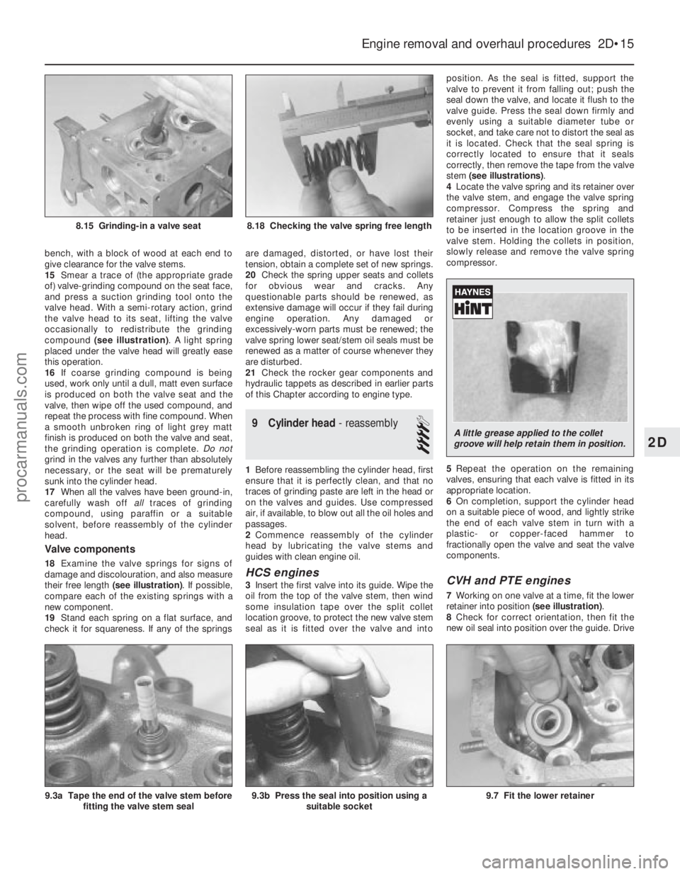
compound (see illustration) . A light spring
placed under the valve head will greatly ease
this operation.
16 If coarse grinding compound is being
used, work only until a dull, matt even surface
is produced on both the valve seat and the
valve, then wipe off the used compound, and
repeat the process with fine compound. When
a smooth unbroken ring of light grey matt
finish is produced on both the valve and seat,
the grinding operation is complete. Do not
grind in the valves any further than absolutely
necessary, or the seat will be prematurely
sunk into the cylinder head.
17 When all the valves have been ground-in,
carefully wash off alltraces of grinding
compound, using paraffin or a suitable
solvent, before reassembly of the cylinder
head.
Valve components
18 Examine the valve springs for signs of
damage and discolouration, and also measure
their free length (see illustration) . If possible,
compare each of the existing springs with a
new component.
19 Stand each spring on a flat surface, and
check it for squareness. If any of the springs are damaged, distorted, or have lost their
tension, obtain a complete set of new springs.
20
Check the spring upper seats and collets
for obvious wear and cracks. Any
questionable parts should be renewed, as
extensive damage will occur if they fail during
engine operation. Any damaged or
excessively-worn parts must be renewed; the
valve spring lower seat/stem oil seals must be
renewed as a matter of course whenever they
are disturbed.
21 Check the rocker gear components and
hydraulic tappets as described in earlier parts
of this Chapter according to engine type.
9 Cylinder head - reassembly
4
1Before reassembling the cylinder head, first
ensure that it is perfectly clean, and that no
traces of grinding paste are left in the head or
on the valves and guides. Use compressed
air, if available, to blow out all the oil holes and
passages.
2 Commence reassembly of the cylinder
head by lubricating the valve stems and
guides with clean engine oil.
HCS engines
3 Insert the first valve into its guide. Wipe the
oil from the top of the valve stem, then wind
some insulation tape over the split collet
location groove, to protect the new valve stem
seal as it is fitted over the valve and into position. As the seal is fitted, support the
valve to prevent it from falling out; push the
seal down the valve, and locate it flush to the
valve guide. Press the seal down firmly and
evenly using a suitable diameter tube or
socket, and take care not to distort the seal as
it is located. Check that the seal spring is
correctly located to ensure that it seals
correctly, then remove the tape from the valve
stem (see illustrations)
.
4 Locate the valve spring and its retainer over
the valve stem, and engage the valve spring
compressor. Compress the spring and
retainer just enough to allow the split collets
to be inserted in the location groove in the
valve stem. Holding the collets in position,
slowly release and remove the valve spring
compressor.
5 Repeat the operation on the remaining
valves, ensuring that each valve is fitted in its
appropriate location.
6 On completion, support the cylinder head
on a suitable piece of wood, and lightly strike
the end of each valve stem in turn with a
plastic- or copper-faced hammer to
fractionally open the valve and seat the valve
components.CVH and PTE engines
7 Working on one valve at a time, fit the lower
retainer into position (see illustration).
8 Check for correct orientation, then fit the
new oil seal into position over the guide. Drive
Engine removal and overhaul procedures 2D•15
9.3a Tape the end of the valve stem before fitting the valve stem seal
8.18 Checking the valve spring free length8.15 Grinding-in a valve seat
9.7 Fit the lower retainer9.3b Press the seal into position using a suitable socket
2D
1595Ford Fiesta Remake
A little grease applied to the collet
groove will help retain them in position.
procarmanuals.com
http://vnx.su
Page 93 of 296
careful not to scratch the bearing - use your
fingernail or the edge of a credit card.
Final crankshaft refitting
18Carefully lift the crankshaft out of the
engine. Clean the bearing surfaces of the
shells in the block, then apply a thin, uniform
layer of clean molybdenum disulphide- based
grease, engine assembly lubricant, or clean
engine oil to each surface. Coat the
thrustwasher surfaces as well.
19 Lubricate the crankshaft oil seal journals
with molybdenum disulphide-based grease,
engine assembly lubricant, or clean engine oil.
20 Make sure the crankshaft journals are
clean, then lay the crankshaft back in place in
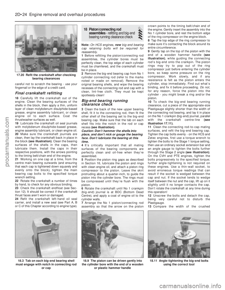
the block (see illustration) . Clean the bearing
surfaces of the shells in the caps, then
lubricate them. Install the caps in their
respective positions, with the arrows pointing
to the timing belt/chain end of the engine.
21 Working on one cap at a time, from the
centre main bearing outwards (and ensuring
that each cap is tightened down squarely and
evenly onto the block), tighten the main
bearing cap bolts to the specified torque
wrench setting.
22 Rotate the crankshaft a number of times
by hand, to check for any obvious binding.
23 Check the crankshaft endfloat (see Sec-
tion 12). It should be correct if the crankshaft
thrust faces aren’t worn or damaged.
24 Refit the crankshaft left-hand oil seal
carrier, and install a new seal (see Part A, B
or C of this Chapter according to engine type).
18 Piston/connecting rod
assemblies - refitting and big-end
bearing running clearance check
4
Note: On HCS engines, new big-end bearing
cap retaining bolts will be required for
reassembly.
1 Before refitting the piston/connecting rod
assemblies, the cylinder bores must be
perfectly clean, the top edge of each cylinder
must be chamfered, and the crankshaft must
be in place.
2 Remove the big-end bearing cap from No 1
cylinder connecting rod (refer to the marks
noted or made on removal). Remove the
original bearing shells, and wipe the bearing
recesses of the connecting rod and cap with a
clean, lint-free cloth. They must be kept
spotlessly-clean!
Big-end bearing running
clearance check
3 Clean the back of the new upper bearing
shell, fit it to the connecting rod, then fit the
other shell of the bearing set to the big-end
bearing cap. Make sure that the tab on each
shell fits into the notch in the rod or cap
recess (see illustration) .
Caution: Don’t hammer the shells into
place, and don’t nick or gouge the bearing
face. Don’t lubricate the bearing at this
time.
4 It’s critically important that all mating
surfaces of the bearing components are
perfectly clean and oil-free when they’re
assembled.
5 Position the piston ring gaps as described
in Section 16, lubricate the piston and rings
with clean engine oil, and attach a piston ring
compressor to the piston. Leave the skirt
protruding about a quarter-inch, to guide the
piston into the cylinder bore. The rings must
be compressed until they’re flush with the
piston.
6 Rotate the crankshaft until No 1 crankpin
(big-end) journal is at BDC (Bottom Dead
Centre), and apply a coat of engine oil to the
cylinder walls.
7 Arrange the No 1 piston/connecting rod
assembly so that the arrow on the piston crown points to the timing belt/chain end of
the engine. Gently insert the assembly into the
No 1 cylinder bore, and rest the bottom edge
of the ring compressor on the engine block.
8
Tap the top edge of the ring compressor to
make sure it’s contacting the block around its
entire circumference.
9 Gently tap on the top of the piston with the
end of a wooden hammer handle (see
illustration) , while guiding the connecting
rod’s big-end onto the crankpin. The piston
rings may try to pop out of the ring
compressor just before entering the cylinder
bore, so keep some pressure on the ring
compressor. Work slowly, and if any
resistance is felt as the piston enters the
cylinder, stop immediately. Find out what’s
binding, and fix it before proceeding. Do not,
for any reason, force the piston into the
cylinder - you might break a ring and/or the
piston.
10 To check the big-end bearing running
clearance, cut a piece of the appropriate-size
Plastigauge slightly shorter than the width of
the connecting rod bearing, and lay it in place
on the No 1 crankpin (big-end) journal, parallel
with the crankshaft centre-line (see
illustration 17.11).
11 Clean the connecting rod-to-cap mating
surfaces, and refit the big-end bearing cap.
Tighten the cap bolts evenly - on the HCS and
Zetec engines, first use a torque wrench to
tighten the bolts to the Stage 1 torque setting,
then use an ordinary socket extension bar and
an angle gauge to tighten the bolts further
through the Stage 2 angle (see illustration).
On the CVH and PTE engines, tighten the
bolts progressively to the specified torque;
further angle-tightening is not required on
these engines. Use a thin-wall socket, to
avoid erroneous torque readings that can
result if the socket is wedged between the
cap and nut. If the socket tends to wedge
itself between the nut and the cap, lift up on it
slightly until it no longer contacts the cap.
Don’t rotate the crankshaft at any time during
this operation!
12 Unscrew the bolts and detach the cap,
being very careful not to disturb the
Plastigauge.
13 Compare the width of the crushed
2D•24 Engine removal and overhaul procedures
18.11 Angle-tightening the big-end bolts
using the correct tool18.9 The piston can be driven gently into
the cylinder bore with the end of a wooden
or plastic hammer handle18.3 Tab on each big-end bearing shell
must engage with notch in connecting rod
or cap
17.20 Refit the crankshaft after checkingbearing clearances
1595Ford Fiesta Remakeprocarmanuals.com
http://vnx.su
Page 97 of 296

Torque wrench settingsNmlbf ft
Thermostat housing to cylinder head: HCS engines . . . . . . . . . . . . . . . . . . . . . . . . . . . . . . . . . . . .\
. . . . . . . . 17 to 21 13 to 16
CVH engines . . . . . . . . . . . . . . . . . . . . . . . . . . . . . . . . . . . .\
. . . . . . . . 9 to 12 7 to 9
PTE engines . . . . . . . . . . . . . . . . . . . . . . . . . . . . . . . . . . . .\
. . . . . . . . 9 7
Zetec engines . . . . . . . . . . . . . . . . . . . . . . . . . . . . . . . . . . . .\
. . . . . . . 17 to 21 13 to 16
Water outlet to thermostat housing (Zetec engines) . . . . . . . . . . . . . . . 9 to 12 7 to 9
Water pump pulley . . . . . . . . . . . . . . . . . . . . . . . . . . . . . . . . . . . .\
. . . . . 107.5
Water pump retaining bolts: HCS, CVH and PTE engines . . . . . . . . . . . . . . . . . . . . . . . . . . . . . . . . 8 6
Zetec engines . . . . . . . . . . . . . . . . . . . . . . . . . . . . . . . . . . . .\
. . . . . . . 1813
Coolant temperature gauge sender . . . . . . . . . . . . . . . . . . . . . . . . . . . . 6 4
Coolant temperature sensor: HCS engines . . . . . . . . . . . . . . . . . . . . . . . . . . . . . . . . . . . .\
. . . . . . . . 2317
CVH engines: 1.4 litre models . . . . . . . . . . . . . . . . . . . . . . . . . . . . . . . . . . . .\
. . . . 1914
1.6 litre models . . . . . . . . . . . . . . . . . . . . . . . . . . . . . . . . . . . .\
. . . . 1511
PTE engines . . . . . . . . . . . . . . . . . . . . . . . . . . . . . . . . . . . .\
. . . . . . . . 1511
Zetec engines . . . . . . . . . . . . . . . . . . . . . . . . . . . . . . . . . . . .\
. . . . . . . 1511
Radiator mounting bolts . . . . . . . . . . . . . . . . . . . . . . . . . . . . . . . . . . . .\
. 20 to 27 15 to 20
Radiator cooling fan shroud retaining bolt . . . . . . . . . . . . . . . . . . . . . . . 3 to 5 2 to 4
Radiator cooling fan motor to shroud nuts . . . . . . . . . . . . . . . . . . . . . . . 9 to 12 7 to 9
Automatic transmission fluid cooling pipe connections to radiator . . . . 17 to 21 13 to 16
3•2 Cooling, heating and ventilation systems
1595Ford Fiesta Remake
1 General information and
precautions
Engine cooling system
The cooling system is of the pressurised
type consisting of a belt-driven pump,
aluminium crossflow radiator, expansion tank,
electric cooling fan and a thermostat. The
system functions as follows. Cold coolant in
the bottom of the radiator passes through the
bottom hose to the water pump, where it is
pumped around the cylinder block and head
passages. After cooling the cylinder bores,
combustion surfaces and valve seats, the
coolant reaches the underside of the
thermostat, which is initially closed. The
coolant passes through the heater and
inlet manifold and is returned to the water
pump. When the engine is cold, the coolant
circulates through the cylinder block, cylinder
head, heater and inlet manifold. When the
coolant reaches a predetermined tempera-
ture, the thermostat opens, and the coolant
then passes through the top hose to
the radiator. As the coolant circulates
through the radiator, it is cooled by the inrush
of air when the car is in forward motion.
Airflow is supplemented by the action of the
electric cooling fan when necessary. Upon
reaching the bottom of the radiator, the
coolant is now cooled, and the cycle is
repeated. When the engine is at normal operating
temperature, the coolant expands, and some
of it is displaced into the expansion tank. This
coolant collects in the tank, and is returned to
the radiator when the system cools.
The electric cooling fan, mounted behind
the radiator, is controlled by a thermostatic switch. At a predetermined coolant
temperature, the switch contacts close, thus
actuating the fan.
Heating/ventilation system
The heating system consists of a blower fan
and heater matrix (radiator) located in the
heater unit, with hoses connecting the heater
matrix to the engine cooling system. Hot
engine coolant is circulated through the
heater matrix. Air is forced through the matrix
by the three-speed fan, dispersing the heat
into the vehicle interior. Fresh air enters the
vehicle through the grille slats between the
windscreen and the rear edge of the bonnet,
and passes through to the heater casing.
Depending on the position of the heater slide
controls, which actuate cable-controlled flap
valves within the heater casing, the air is
distributed, either heated or unheated, via the
ducting to outlet vents. The main outlet vents
in the facia are adjustable. The airflow passes
through the passenger compartment to exit at
the rear of the vehicle.
Precautions
Warning: DO NOT attempt to
remove the expansion tank filler
cap, or to disturb any part of the
cooling system, while it or the
engine is hot, as there is a very great risk
of scalding. If the expansion tank filler cap
must be removed before the engine and
radiator have fully cooled down (even
though this is not recommended) the
pressure in the cooling system must first
be released. Cover the cap with a thick
layer of cloth, to avoid scalding, and slowly
unscrew the filler cap until a hissing sound
can be heard. When the hissing has
stopped, showing that pressure is
released, slowly unscrew the filler cap
further until it can be removed; if more
hissing sounds are heard, wait until they have stopped before unscrewing the cap
completely. At all times, keep well away
from the filler opening.
Warning: Do not allow antifreeze
to come in contact with your
skin, or with the painted
surfaces of the vehicle. Rinse off
spills immediately with plenty of water.
Never leave antifreeze lying around in an
open container, or in a puddle in the
driveway or on the garage floor. Children
and pets are attracted by its sweet smell,
but antifreeze can be fatal if ingested. Warning: If the engine is hot, the
electric cooling fan may start
rotating even if the engine is not
running, so be careful to keep
hands, hair and loose clothing well clear
when working in the engine compartment.
2 Antifreeze -
general information
Note: Refer to the warnings given in Section 1
of this Chapter before proceeding. The cooling system should be filled with a
water/ethylene glycol-based antifreeze
solution, of a strength which will prevent
freezing down to at least -25ºC, or lower if the
local climate requires it. Antifreeze also
provides protection against corrosion, and
increases the coolant boiling point. The cooling system should be maintained
according to the schedule described in
Chapter 1. If antifreeze is used that is not to
Ford’s specification, old or contaminated
coolant mixtures are likely to cause damage,
and encourage the formation of corrosion and
scale in the system. Use distilled water with the
antifreeze, if available - if not, be sure to use
only soft water. Clean rainwater is suitable.
procarmanuals.com
http://vnx.su