change wheel FORD FIESTA 1989 Service Repair Manual
[x] Cancel search | Manufacturer: FORD, Model Year: 1989, Model line: FIESTA, Model: FORD FIESTA 1989Pages: 296, PDF Size: 10.65 MB
Page 5 of 296
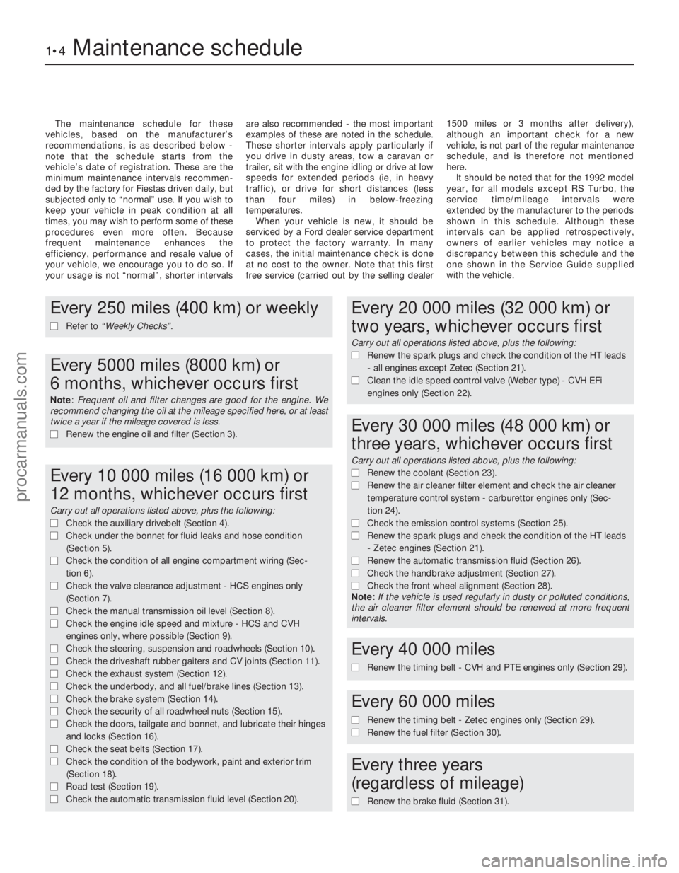
The maintenance schedule for these
vehicles, based on the manufacturer’s
recommendations, is as described below -
note that the schedule starts from the
vehicle’s date of registration. These are the
minimum maintenance intervals recommen-
ded by the factory for Fiestas driven daily, but
subjected only to “normal” use. If you wish to
keep your vehicle in peak condition at all
times, you may wish to perform some of these
procedures even more often. Because
frequent maintenance enhances the
efficiency, performance and resale value of
your vehicle, we encourage you to do so. If
your usage is not “normal”, shorter intervals are also recommended - the most important
examples of these are noted in the schedule.
These shorter intervals apply particularly if
you drive in dusty areas, tow a caravan or
trailer, sit with the engine idling or drive at low
speeds for extended periods (ie, in heavy
traffic), or drive for short distances (less
than four miles) in below-freezing
temperatures.
When your vehicle is new, it should be
serviced by a Ford dealer service department
to protect the factory warranty. In many
cases, the initial maintenance check is done
at no cost to the owner. Note that this first
free service (carried out by the selling dealer 1500 miles or 3 months after delivery),
although an important check for a new
vehicle, is not part of the regular maintenance
schedule, and is therefore not mentioned
here.
It should be noted that for the 1992 model
year, for all models except RS Turbo, the
service time/mileage intervals were
extended by the manufacturer to the periods
shown in this schedule. Although these
intervals can be applied retrospectively,
owners of earlier vehicles may notice a
discrepancy between this schedule and the
one shown in the Service Guide supplied
with the vehicle.
1•4Maintenance schedule
1595Ford Fiesta Remake
Every 250 miles (400 km) or weekly
m
m Refer to “Weekly Checks” .
Every 5000 miles (8000 km) or
6 months, whichever occurs first
Note: Frequent oil and filter changes are good for the engine. We
recommend changing the oil at the mileage specified here, or at least
twice a year if the mileage covered is less.
m m Renew the engine oil and filter (Section 3).
Every 10 000 miles (16 000 km) or
12 months, whichever occurs first
Carry out all operations listed above, plus the following:
m mCheck the auxiliary drivebelt (Section 4).
m
m Check under the bonnet for fluid leaks and hose condition
(Section 5).
m
m Check the condition of all engine compartment wiring (Sec-
tion 6).
m
m Check the valve clearance adjustment - HCS engines only
(Section 7).
m
m Check the manual transmission oil level (Section 8).
m
m Check the engine idle speed and mixture - HCS and CVH
engines only, where possible (Section 9).
m
m Check the steering, suspension and roadwheels (Section 10).
m
m Check the driveshaft rubber gaiters and CV joints (Section 11).
m
m Check the exhaust system (Section 12).
m
m Check the underbody, and all fuel/brake lines (Section 13).
m
m Check the brake system (Section 14).
m
m Check the security of all roadwheel nuts (Section 15).
m
m Check the doors, tailgate and bonnet, and lubricate their hinges
and locks (Section 16).
m
m Check the seat belts (Section 17).
m
m Check the condition of the bodywork, paint and exterior trim
(Section 18).
m
m Road test (Section 19).
m
m Check the automatic transmission fluid level (Section 20).
Every 20 000 miles (32 000 km) or
two years, whichever occurs first
Carry out all operations listed above, plus the following:
m mRenew the spark plugs and check the condition of the HT leads
- all engines except Zetec (Section 21).
m
m Clean the idle speed control valve (Weber type) - CVH EFi
engines only (Section 22).
Every 30 000 miles (48 000 km) or
three years, whichever occurs first
Carry out all operations listed above, plus the following:
m m Renew the coolant (Section 23).
m
m Renew the air cleaner filter element and check the air cleaner
temperature control system - carburettor engines only (Sec-
tion 24).
m m Check the emission control systems (Section 25).
m
m Renew the spark plugs and check the condition of the HT leads
- Zetec engines (Section 21).
m
m Renew the automatic transmission fluid (Section 26).
m
m Check the handbrake adjustment (Section 27).
m
m Check the front wheel alignment (Section 28).
Note: If the vehicle is used regularly in dusty or polluted conditions,
the air cleaner filter element should be renewed at more frequent
intervals.
Every 40 000 miles
m
m Renew the timing belt - CVH and PTE engines only (Section 29).
Every 60 000 miles
m
mRenew the timing belt - Zetec engines only (Section 29).
m
m Renew the fuel filter (Section 30).
Every three years
(regardless of mileage)
m m Renew the brake fluid (Section 31).
procarmanuals.com
http://vnx.su
Page 10 of 296
3 Engine oil and filter renewal
1
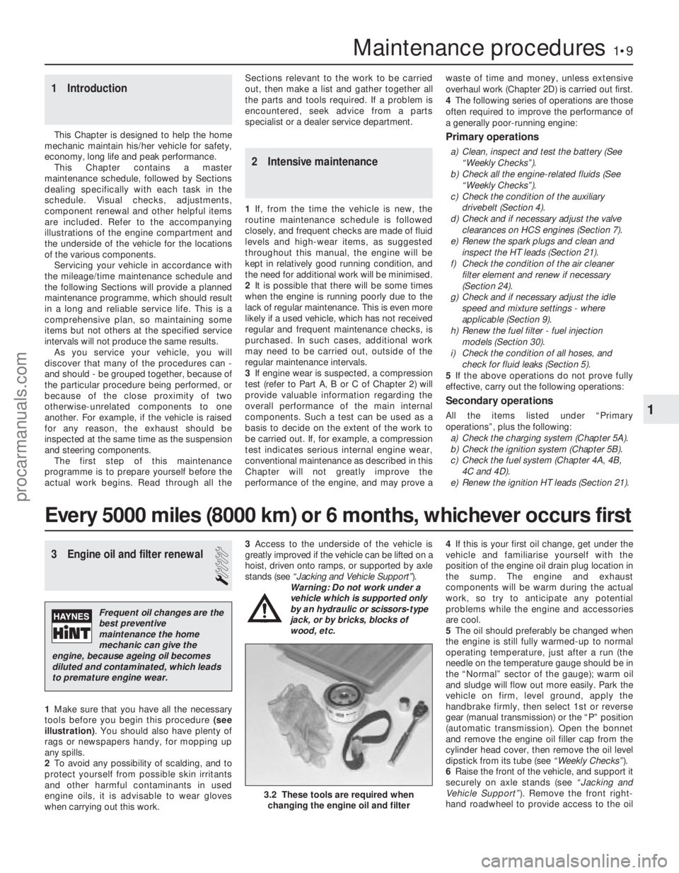
1Make sure that you have all the necessary
tools before you begin this procedure (see
illustration) . You should also have plenty of
rags or newspapers handy, for mopping up
any spills.
2 To avoid any possibility of scalding, and to
protect yourself from possible skin irritants
and other harmful contaminants in used
engine oils, it is advisable to wear gloves
when carrying out this work. 3
Access to the underside of the vehicle is
greatly improved if the vehicle can be lifted on a
hoist, driven onto ramps, or supported by axle
stands (see “Jacking and Vehicle Support” ).
Warning: Do not work under a
vehicle which is supported only
by an hydraulic or scissors-type
jack, or by bricks, blocks of
wood, etc. 4
If this is your first oil change, get under the
vehicle and familiarise yourself with the
position of the engine oil drain plug location in
the sump. The engine and exhaust
components will be warm during the actual
work, so try to anticipate any potential
problems while the engine and accessories
are cool.
5 The oil should preferably be changed when
the engine is still fully warmed-up to normal
operating temperature, just after a run (the
needle on the temperature gauge should be in
the “Normal” sector of the gauge); warm oil
and sludge will flow out more easily. Park the
vehicle on firm, level ground, apply the
handbrake firmly, then select 1st or reverse
gear (manual transmission) or the “P” position
(automatic transmission). Open the bonnet
and remove the engine oil filler cap from the
cylinder head cover, then remove the oil level
dipstick from its tube (see “Weekly Checks”).
6 Raise the front of the vehicle, and support it
securely on axle stands (see “Jacking and
Vehicle Support” ). Remove the front right-
hand roadwheel to provide access to the oil
1 Introduction
This Chapter is designed to help the home
mechanic maintain his/her vehicle for safety,
economy, long life and peak performance.
This Chapter contains a master
maintenance schedule, followed by Sections
dealing specifically with each task in the
schedule. Visual checks, adjustments,
component renewal and other helpful items
are included. Refer to the accompanying
illustrations of the engine compartment and
the underside of the vehicle for the locations
of the various components.
Servicing your vehicle in accordance with
the mileage/time maintenance schedule and
the following Sections will provide a planned
maintenance programme, which should result
in a long and reliable service life. This is a
comprehensive plan, so maintaining some
items but not others at the specified service
intervals will not produce the same results. As you service your vehicle, you will
discover that many of the procedures can -
and should - be grouped together, because of
the particular procedure being performed, or
because of the close proximity of two
otherwise-unrelated components to one
another. For example, if the vehicle is raised
for any reason, the exhaust should be
inspected at the same time as the suspension
and steering components.
The first step of this maintenance
programme is to prepare yourself before the
actual work begins. Read through all the Sections relevant to the work to be carried
out, then make a list and gather together all
the parts and tools required. If a problem is
encountered, seek advice from a parts
specialist or a dealer service department.
2 Intensive maintenance
1
If, from the time the vehicle is new, the
routine maintenance schedule is followed
closely, and frequent checks are made of fluid
levels and high-wear items, as suggested
throughout this manual, the engine will be
kept in relatively good running condition, and
the need for additional work will be minimised.
2 It is possible that there will be some times
when the engine is running poorly due to the
lack of regular maintenance. This is even more
likely if a used vehicle, which has not received
regular and frequent maintenance checks, is
purchased. In such cases, additional work
may need to be carried out, outside of the
regular maintenance intervals.
3 If engine wear is suspected, a compression
test (refer to Part A, B or C of Chapter 2) will
provide valuable information regarding the
overall performance of the main internal
components. Such a test can be used as a
basis to decide on the extent of the work to
be carried out. If, for example, a compression
test indicates serious internal engine wear,
conventional maintenance as described in this
Chapter will not greatly improve the
performance of the engine, and may prove a waste of time and money, unless extensive
overhaul work (Chapter 2D) is carried out first.
4
The following series of operations are those
often required to improve the performance of
a generally poor-running engine:
Primary operations
a) Clean, inspect and test the battery (See
“Weekly Checks”).
b) Check all the engine-related fluids (See
“Weekly Checks”).
c) Check the condition of the auxiliary drivebelt (Section 4).
d) Check and if necessary adjust the valve
clearances on HCS engines (Section 7).
e) Renew the spark plugs and clean and inspect the HT leads (Section 21).
f) Check the condition of the air cleaner filter element and renew if necessary
(Section 24).
g) Check and if necessary adjust the idle speed and mixture settings - where
applicable (Section 9).
h) Renew the fuel filter - fuel injection models (Section 30).
i) Check the condition of all hoses, and check for fluid leaks (Section 5).
5 If the above operations do not prove fully
effective, carry out the following operations:
Secondary operations
All the items listed under “Primary
operations”, plus the following: a) Check the charging system (Chapter 5A).
b) Check the ignition system (Chapter 5B).
c) Check the fuel system (Chapter 4A, 4B,
4C and 4D).
e) Renew the ignition HT leads (Section 21).
Maintenance procedures1•9
3.2 These tools are required when changing the engine oil and filter
1
1595Ford Fiesta Remake
Every 5000 miles (8000 km) or 6 months, whichever occurs first
Frequent oil changes are the
best preventive
maintenance the home
mechanic can give the
engine, because ageing oil becomes
diluted and contaminated, which leads
to premature engine wear.
procarmanuals.com
http://vnx.su
Page 19 of 296
3Check that the roadwheel nuts are tightened
to the specified torque wrench setting.
4 Refit the wheel covers.
16 Door, tailgate and bonnet
check and lubrication
1
1Check that the doors and tailgate/boot lid
close securely. Check that the bonnet safety
catch operates correctly. Check the operation
of the door check straps.
2 Lubricate the hinges, door check straps,
the striker plates and the bonnet catch
sparingly with a little oil or grease.
17 Seat belt check
1
1 Check the seat belts for satisfactory
operation and condition. Inspect the webbing
for fraying and cuts. Check that they retract
smoothly and without binding into their reels.
2 Check that the seat belt mounting bolts are
tight, and if necessary tighten them to the
specified torque wrench settings as given in
Chapter 11.
18 Bodywork, paint and exterior trim check
1
1The best time to carry out this check is after
the car has been washed so that any surface
blemish or scratch will be clearly evident and
not hidden by a film of dirt.
2 Starting at one front corner check the
paintwork all around the car, looking for minor
scratches or more serious dents. Check all
the trim and make sure that it is securely
attached over its entire length.
3 Check the security of all door locks, door
mirrors, badges, bumpers, front grille and
wheel trim. Anything found loose, or in need of
further attention should be done with reference
to the relevant Chapters of this manual.
4 Rectify any problems noticed with the
paintwork or body panels as described in
Chapter 11.
19 Road test
1
Check the operation and
performance of the braking
system
1 Make sure that the vehicle does not pull to
one side when braking, and that the wheels
do not lock prematurely when braking hard.
2 Check that there is no vibration through the
steering when braking. 3
Check that the handbrake operates
correctly, without excessive movement of the
lever, and that it holds the vehicle stationary
on a slope.
4 Test the operation of the brake servo unit
as follows. With the engine switched off,
depress the footbrake four or five times to
exhaust the vacuum, then hold the pedal
depressed. Start the engine, and there should
be a noticeable “give” in the brake pedal as
vacuum builds up. Allow the engine to run for
at least two minutes, and then switch it off. If
the brake pedal is depressed again, it should
be possible to detect a hiss from the servo as
the pedal is depressed. After about four or five
applications, no further hissing should be
heard, and the pedal should feel considerably
firmer.
Steering and suspension
5 Check for any abnormalities in the steering,
suspension, handling or road “feel”.
6 Drive the vehicle, and check that there are
no unusual vibrations or noises.
7 Check that the steering feels positive, with
no excessive sloppiness or roughness, and
check for any suspension noises when
cornering and driving over bumps.
Drivetrain
8 Check the performance of the engine,
transmission and driveshafts.
9 Check that the engine starts correctly, both
when cold and when hot.
10 Listen for any unusual noises from the
engine and transmission.
11 Make sure that the engine runs smoothly
when idling, and that there is no hesitation
when accelerating.
12 On manual transmission models, check
that all gears can be engaged smoothly
without noise, and that the gear lever action is
not abnormally vague or “notchy”.
13 On automatic transmission models, make
sure that the drive seems smooth without
jerks or engine speed “flare-ups”. Check that
all the gear positions can be selected with the
vehicle at rest. If any problems are found, they
should be referred to a Ford dealer.
14 Listen for a metallic clicking sound from
the front of the vehicle, as the vehicle is driven
slowly in a circle with the steering on full-lock.
Carry out this check in both directions. If a
clicking noise is heard, this indicates wear in a
driveshaft joint, in which case renew the joint
if necessary.
Clutch
15 Check that the clutch pedal moves
smoothly and easily through its full travel, and
that the clutch itself functions correctly, with
no trace of slip or drag. If the movement is
uneven or stiff in places, check that the cable
is routed correctly, with no sharp turns.
16 Inspect both ends of the clutch inner
cable, both at the transmission end and inside
the car, for signs of wear and fraying.
Instruments and electrical
equipment
17 Check the operation of all instruments
and electrical equipment.
18 Make sure that all instruments read
correctly, and switch on all electrical equipment
in turn, to check that it functions properly.
20 Automatic transmission fluid level check
1
1The level of the automatic transmission fluid
should be carefully maintained. Low fluid level
can lead to slipping or loss of drive, while
overfilling can cause foaming, loss of fluid and
transmission damage.
2 The transmission fluid level should only be
checked when the transmission is hot (at its
normal operating temperature). If the vehicle
has just been driven over 10 miles (15 miles in
a cold climate), and the fluid temperature is 60
to 70ºC, the transmission is hot.
Caution: If the vehicle has just been driven
for a long time at high speed or in city
traffic in hot weather, or if it has been
pulling a trailer, an accurate fluid level
reading cannot be obtained. In these
circumstances, allow the fluid to cool
down for about 30 minutes.
3 Park the vehicle on level ground, apply the
handbrake, and start the engine. While the
engine is idling, depress the brake pedal and
move the selector lever through all the gear
positions three times, beginning and ending in
“P”.
4 Allow the engine to idle for one minute, then
(with the engine still idling) remove the
dipstick from its tube. Note the condition and
colour of the fluid on the dipstick.
5 Wipe the fluid from the dipstick with a clean
rag, and re-insert it into the filler tube until the
cap seats.
6 Pull the dipstick out again, and note the
fluid level. The level should be between
the “MIN” and “MAX” marks. If the level is
on the “MIN” mark, stop the engine, and add
the specified automatic transmission fluid
through the dipstick tube, using a clean funnel
if necessary. It is important not to introduce
dirt into the transmission when topping-up.
7 Add the fluid a little at a time, and keep
checking the level as previously described
until it is correct. The difference between the
“MIN” and “MAX” marks on the dipstick is
approximately 0.4 litres.
8 The need for regular topping-up of the
transmission fluid indicates a leak, which
should be found and rectified without delay.
9 The condition of the fluid should also be
checked along with the level. If the fluid on the
dipstick is black or a dark reddish-brown
colour, or if it has a burned smell, the fluid
should be changed. If you are in doubt about
the condition of the fluid, purchase some new
fluid, and compare the two for colour and smell.
1•18Every 10 000 miles or 12 months
1595Ford Fiesta Remakeprocarmanuals.com
http://vnx.su
Page 43 of 296
complete turn, and all the markings should
now align.
7With the engine set at No 1 piston on TDC
compression, refit the crankshaft pulley cover,
lower the vehicle and refit the upper timing
belt cover.
4 Cylinder head rocker cover -
removal and refitting
2
Removal
1 Disconnect the battery negative (earth) lead
(refer to Chapter 5A, Section 1).
2 Remove the air cleaner assembly and air
inlet components as necessary for access as
described in the relevant Part of Chapter 4.
Disconnect the crankcase ventilation hose
from the rocker cover.
3 Remove the timing belt upper cover as
described in Section 7.
4 Referring to the relevant Part of Chapter 4
for details, disconnect the accelerator cable
from the throttle linkage and from the adjuster
bracket above the rocker cover. Position the
cable out of the way.
5 Where applicable, disconnect the choke
cable from the carburettor, referring to
Chapter 4A for details.
6 Unscrew and remove the rocker cover
retaining bolts and washers, then lift the cover
from the cylinder head. Note that a new
rocker cover gasket will be needed on
refitting.
Refitting
7 Before refitting the rocker cover, clean the
mating surfaces of both the cylinder head and
the cover.
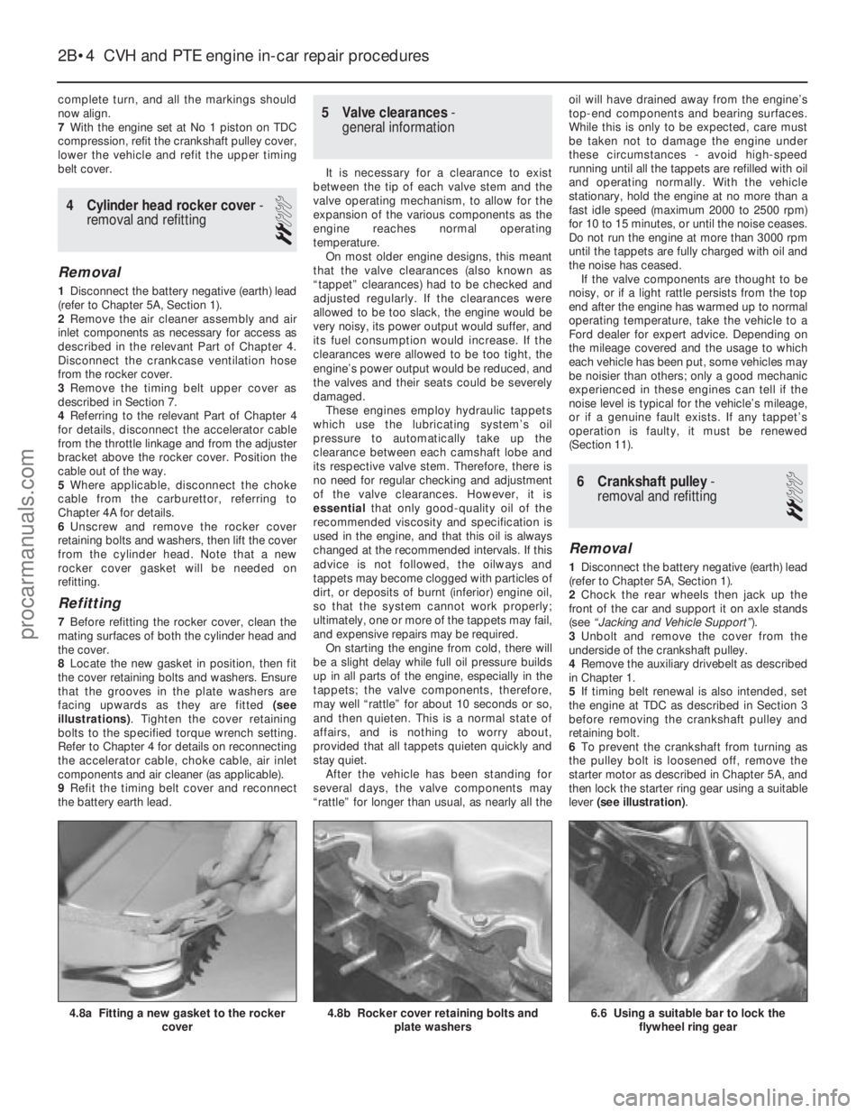
8 Locate the new gasket in position, then fit
the cover retaining bolts and washers. Ensure
that the grooves in the plate washers are
facing upwards as they are fitted (see
illustrations) . Tighten the cover retaining
bolts to the specified torque wrench setting.
Refer to Chapter 4 for details on reconnecting
the accelerator cable, choke cable, air inlet
components and air cleaner (as applicable).
9 Refit the timing belt cover and reconnect
the battery earth lead.
5 Valve clearances -
general information
It is necessary for a clearance to exist
between the tip of each valve stem and the
valve operating mechanism, to allow for the
expansion of the various components as the
engine reaches normal operating
temperature. On most older engine designs, this meant
that the valve clearances (also known as
“tappet” clearances) had to be checked and
adjusted regularly. If the clearances were
allowed to be too slack, the engine would be
very noisy, its power output would suffer, and
its fuel consumption would increase. If the
clearances were allowed to be too tight, the
engine’s power output would be reduced, and
the valves and their seats could be severely
damaged. These engines employ hydraulic tappets
which use the lubricating system’s oil
pressure to automatically take up the
clearance between each camshaft lobe and
its respective valve stem. Therefore, there is
no need for regular checking and adjustment
of the valve clearances. However, it is
essential that only good-quality oil of the
recommended viscosity and specification is
used in the engine, and that this oil is always
changed at the recommended intervals. If this
advice is not followed, the oilways and
tappets may become clogged with particles of
dirt, or deposits of burnt (inferior) engine oil,
so that the system cannot work properly;
ultimately, one or more of the tappets may fail,
and expensive repairs may be required. On starting the engine from cold, there will
be a slight delay while full oil pressure builds
up in all parts of the engine, especially in the
tappets; the valve components, therefore,
may well “rattle” for about 10 seconds or so,
and then quieten. This is a normal state of
affairs, and is nothing to worry about,
provided that all tappets quieten quickly and
stay quiet. After the vehicle has been standing for
several days, the valve components may
“rattle” for longer than usual, as nearly all the oil will have drained away from the engine’s
top-end components and bearing surfaces.
While this is only to be expected, care must
be taken not to damage the engine under
these circumstances - avoid high-speed
running until all the tappets are refilled with oil
and operating normally. With the vehicle
stationary, hold the engine at no more than a
fast idle speed (maximum 2000 to 2500 rpm)
for 10 to 15 minutes, or until the noise ceases.
Do not run the engine at more than 3000 rpm
until the tappets are fully charged with oil and
the noise has ceased.
If the valve components are thought to be
noisy, or if a light rattle persists from the top
end after the engine has warmed up to normal
operating temperature, take the vehicle to a
Ford dealer for expert advice. Depending on
the mileage covered and the usage to which
each vehicle has been put, some vehicles may
be noisier than others; only a good mechanic
experienced in these engines can tell if the
noise level is typical for the vehicle’s mileage,
or if a genuine fault exists. If any tappet’s
operation is faulty, it must be renewed
(Section 11).
6 Crankshaft pulley -
removal and refitting
2
Removal
1 Disconnect the battery negative (earth) lead
(refer to Chapter 5A, Section 1).
2 Chock the rear wheels then jack up the
front of the car and support it on axle stands
(see “Jacking and Vehicle Support” ).
3 Unbolt and remove the cover from the
underside of the crankshaft pulley.
4 Remove the auxiliary drivebelt as described
in Chapter 1.
5 If timing belt renewal is also intended, set
the engine at TDC as described in Section 3
before removing the crankshaft pulley and
retaining bolt.
6 To prevent the crankshaft from turning as
the pulley bolt is loosened off, remove the
starter motor as described in Chapter 5A, and
then lock the starter ring gear using a suitable
lever (see illustration) .
2B•4 CVH and PTE engine in-car repair procedures
6.6 Using a suitable bar to lock the
flywheel ring gear4.8b Rocker cover retaining bolts and plate washers4.8a Fitting a new gasket to the rocker cover
1595Ford Fiesta Remakeprocarmanuals.com
http://vnx.su
Page 56 of 296
fitted with three piston rings: two
compression rings and an oil control ring.
After manufacture, the cylinder bores and
piston skirts are measured and classified into
three grades, which must be carefully
matched together, to ensure the correct
piston/cylinder clearance; no oversizes are
available to permit reboring.The inlet and exhaust valves are each
closed by coil springs; they operate in guides
which are shrink-fitted into the cylinder head,
as are the valve seat inserts. Both camshafts are driven by the same
toothed timing belt, each operating eight
valves via self-adjusting hydraulic tappets,
thus eliminating the need for routine checking
and adjustment of the valve clearances. Each
camshaft rotates in five bearings that are line-
bored directly in the cylinder head and the
(bolted-on) bearing caps; this means that the
bearing caps are not available separately from
the cylinder head, and must not be
interchanged with caps from another engine. The water pump is bolted to the right-hand
end of the cylinder block, inboard of the
timing belt, and is driven with the power
steering pump and alternator by a flat
“polyvee”-type auxiliary drivebelt from the
crankshaft pulley.
When working on this engine, note that
Torx-type (both male and female heads) and
hexagon socket (Allen head) fasteners are
widely used; a good selection of bits, with the
necessary adapters, will be required, so that
these can be unscrewed without damage and,
on reassembly, tightened to the torque
wrench settings specified. Lubrication is by means of an eccentric-
rotor trochoidal pump, which is mounted on
the crankshaft right-hand end, and draws oil
through a strainer located in the sump. The
pump forces oil through an externally-
mounted full-flow cartridge-type filter - on
some versions of the engine, an oil cooler is
fitted to the oil filter mounting, so that clean oil
entering the engine’s galleries is cooled by the
main engine cooling system.
Repair operations possible with
the engine in the car
The following work can be carried out with
the engine in the car:
a) Compression pressure - testing.
b) Cylinder head cover - removal and
refitting.
c) Timing belt covers - removal and refitting.
d) Timing belt - renewal.
e) Timing belt tensioner and sprockets - removal and refitting.
f) Camshaft oil seals - renewal.
g) Camshafts and hydraulic tappets - removal and refitting.
h) Cylinder head - removal and refitting.
i) Cylinder head and pistons - decarbonising.
j) Sump - removal and refitting.
k) Crankshaft oil seals - renewal.
l) Oil pump - removal and refitting. m)
Flywheel/driveplate - removal and
refitting.
n) Engine/transmission mountings - removal and refitting.
Note: It is possible to remove the pistons and
connecting rods (after removing the cylinder
head and sump) without removing the engine.
However, this is not recommended. Work of
this nature is more easily and thoroughly
completed with the engine on the bench, as
described in Chapter 2D.
2 Compression test -
description and interpretation
2
Refer to Section 2 in Part A of this Chapter.
3 Top Dead Centre (TDC) for No 1 piston - locating
2
1Top dead centre (TDC) is the highest point
of the cylinder that each piston reaches as the
crankshaft turns. Each piston reaches its TDC
position at the end of its compression stroke,
and then again at the end of its exhaust
stroke. For the purpose of engine timing, TDC
on the compression stroke for No 1 piston is
used. No 1 cylinder is at the timing belt end of
the engine. Proceed as follows.
2 Disconnect the battery negative (earth) lead
(refer to Chapter 5A, Section 1).
3 Chock the rear wheels then jack up the
front of the car and support it on axle stands
(see “Jacking and Vehicle Support” ). Remove
the right-hand roadwheel.
4 Remove the auxiliary drivebelt cover (see
Chapter 1) to expose the crankshaft pulley
and timing marks.
5 Fit a spanner onto the crankshaft pulley
bolt, and turn the crankshaft in its normal
direction of rotation (clockwise, viewed from
the pulley end). 6
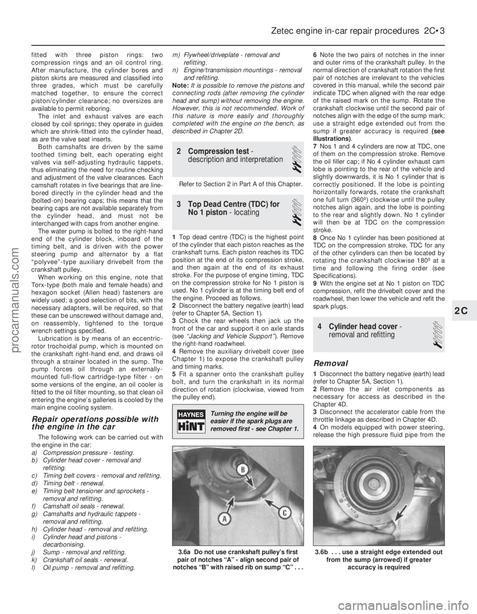
Note the two pairs of notches in the inner
and outer rims of the crankshaft pulley. In the
normal direction of crankshaft rotation the first
pair of notches are irrelevant to the vehicles
covered in this manual, while the second pair
indicate TDC when aligned with the rear edge
of the raised mark on the sump. Rotate the
crankshaft clockwise until the second pair of
notches align with the edge of the sump mark;
use a straight edge extended out from the
sump if greater accuracy is required (see
illustrations) .
7 Nos 1 and 4 cylinders are now at TDC, one
of them on the compression stroke. Remove
the oil filler cap; if No 4 cylinder exhaust cam
lobe is pointing to the rear of the vehicle and
slightly downwards, it is No 1 cylinder that is
correctly positioned. If the lobe is pointing
horizontally forwards, rotate the crankshaft
one full turn (360º) clockwise until the pulley
notches align again, and the lobe is pointing
to the rear and slightly down. No 1 cylinder
will then be at TDC on the compression
stroke.
8 Once No 1 cylinder has been positioned at
TDC on the compression stroke, TDC for any
of the other cylinders can then be located by
rotating the crankshaft clockwise 180º at a
time and following the firing order (see
Specifications).
9 With the engine set at No 1 piston on TDC
compression, refit the drivebelt cover and the
roadwheel, then lower the vehicle and refit the
spark plugs.
4 Cylinder head cover -
removal and refitting
1
Removal
1 Disconnect the battery negative (earth) lead
(refer to Chapter 5A, Section 1).
2 Remove the air inlet components as
necessary for access as described in the
Chapter 4D.
3 Disconnect the accelerator cable from the
throttle linkage as described in Chapter 4D.
4 On models equipped with power steering,
release the high pressure fluid pipe from the
Zetec engine in-car repair procedures 2C•3
3.6b . . . use a straight edge extended out from the sump (arrowed) if greater
accuracy is required3.6a Do not use crankshaft pulley’s first
pair of notches “A” - align second pair of
notches “B” with raised rib on sump “C” . . .
2C
1595Ford Fiesta Remake
Turning the engine will be
easier if the spark plugs are
removed first - see Chapter 1.
procarmanuals.com
http://vnx.su
Page 78 of 296
7Refer to the relevant Part of Chapter 4 for
details, and disconnect the accelerator cable
from the throttle linkage and support/adjuster
bracket. Where applicable, also disconnect
the choke cable. Position the cable(s) out of
the way.
8 On carburettor models, disconnect the fuel
supply hose from the fuel pump, and the
return hose from the carburettor.
9 On CFi models, detach the fuel hose at the
injector/pressure regulator unit, and the return
line, by compressing the couplings whilst
pulling the hoses free from their connections.
On EFi and SEFi models, unscrew the union
nut to detach the fuel line from the fuel rail;
release the retaining clip to detach the return
pipe from the pressure regulator. Plug the
exposed ends of the hoses and connections,
to prevent fuel spillage and the ingress of dirt.
Position the hoses out of the way.
10 Press the clamp ring inwards, and
simultaneously pull free the brake servo hose from the inlet manifold. Position it out of the
way.
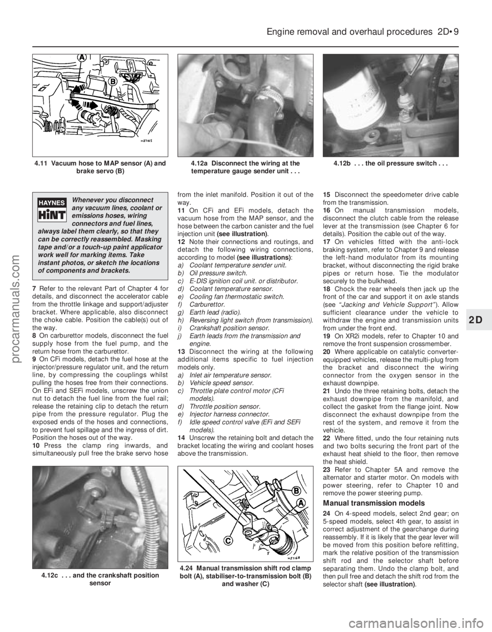
11
On CFi and EFi models, detach the
vacuum hose from the MAP sensor, and the
hose between the carbon canister and the fuel
injection unit (see illustration) .
12 Note their connections and routings, and
detach the following wiring connections,
according to model (see illustrations):
a) Coolant temperature sender unit.
b) Oil pressure switch.
c) E-DIS ignition coil unit. or distributor.
d) Coolant temperature sensor.
e) Cooling fan thermostatic switch.
f) Carburettor.
g) Earth lead (radio).
h) Reversing light switch (from transmission).
i) Crankshaft position sensor.
j) Earth leads from the transmission and engine.
13 Disconnect the wiring at the following
additional items specific to fuel injection
models only.
a) Inlet air temperature sensor.
b) Vehicle speed sensor.
c) Throttle plate control motor (CFi models).
d) Throttle position sensor.
e) Injector harness connector.
f) Idle speed control valve (EFi and SEFi models).
14 Unscrew the retaining bolt and detach the
bracket locating the wiring and coolant hoses
above the transmission. 15
Disconnect the speedometer drive cable
from the transmission.
16 On manual transmission models,
disconnect the clutch cable from the release
lever at the transmission (see Chapter 6 for
details). Position the cable out of the way.
17 On vehicles fitted with the anti-lock
braking system, refer to Chapter 9 and release
the left-hand modulator from its mounting
bracket, without disconnecting the rigid brake
pipes or return hose. Tie the modulator
securely to the bulkhead.
18 Chock the rear wheels then jack up the
front of the car and support it on axle stands
(see “Jacking and Vehicle Support” ). Allow
sufficient clearance under the vehicle to
withdraw the engine and transmission units
from under the front end.
19 On XR2i models, refer to Chapter 10 and
remove the front suspension crossmember.
20 Where applicable on catalytic converter-
equipped vehicles, release the multi-plug from
the bracket and disconnect the wiring
connector from the oxygen sensor in the
exhaust downpipe.
21 Undo the three retaining bolts, detach the
exhaust downpipe from the manifold, and
collect the gasket from the flange joint. Now
disconnect the exhaust downpipe from the
rest of the system, and remove it from the
vehicle.
22 Where fitted, undo the four retaining nuts
and two bolts securing the front part of the
exhaust heat shield to the floor, then remove
the heat shield.
23 Refer to Chapter 5A and remove the
alternator and starter motor. On models with
power steering, refer to Chapter 10 and
remove the power steering pump.
Manual transmission models
24 On 4-speed models, select 2nd gear; on
5-speed models, select 4th gear, to assist in
correct adjustment of the gearchange during
reassembly. If it is likely that the gear lever will
be moved from this position before refitting,
mark the relative position of the transmission
shift rod and the selector shaft before
separating them. Undo the clamp bolt, and
then pull free and detach the shift rod from the
selector shaft (see illustration) .
Engine removal and overhaul procedures 2D•9
4.12b . . . the oil pressure switch . . .4.12a Disconnect the wiring at the
temperature gauge sender unit . . .4.11 Vacuum hose to MAP sensor (A) and brake servo (B)
4.24 Manual transmission shift rod clamp
bolt (A), stabiliser-to-transmission bolt (B)
and washer (C)4.12c . . . and the crankshaft position sensor
2D
1595Ford Fiesta Remake
Whenever you disconnect
any vacuum lines, coolant or
emissions hoses, wiring
connectors and fuel lines,
always label them clearly, so that they
can be correctly reassembled. Masking
tape and/or a touch-up paint applicator
work well for marking items. Take
instant photos, or sketch the locations
of components and brackets.
procarmanuals.com
http://vnx.su
Page 80 of 296
8Disconnect the accelerator cable from the
throttle linkage as described in Chapter 4D.
Secure the cable clear of the
engine/transmission.
9 Releasing its wire clip, unplug the wiring
connector from the power steering pressure
switch (where fitted), then disconnect the
earth cable from the engine lifting eye. Refit
the bolt after disconnecting the cable.
10 Marking or labelling all components as
they are disconnected, disconnect the
vacuum hoses as follows:
a) From the rear of the inlet manifold.
b) The braking system vacuum servo unit
hose - from the inlet manifold (see
Chapter 9 for details).
c) While you are there, trace the vacuum line
from the pulse-air filter housing, and
disconnect it from the pulse-air solenoid
valve.
d) Secure all these hoses so that they won’t
get damaged as the engine/transmission
is removed.
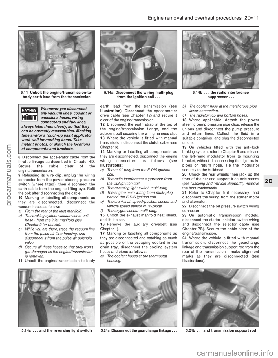
11 Unbolt the engine/transmission-to-body earth lead from the transmission
(see
illustration) . Disconnect the speedometer
drive cable (see Chapter 12) and secure it
clear of the engine/transmission.
12 Disconnect the earth strap at the top of
the engine/transmission flange, and the
adjacent bolt securing the wiring harness clip.
13 Where the vehicle is fitted with manual
transmission, disconnect the clutch cable (see
Chapter 6).
14 Marking or labelling all components as
they are disconnected, disconnect the engine
wiring connectors as follows (see
illustrations) :
a) The multi-plug from the E-DIS ignition
coil.
b) The radio interference suppressor from
the DIS ignition coil.
c) The reversing light switch multi-plug.
d) The engine main wiring loom multi-plug
behind the E-DIS ignition coil.
e) The crankshaft speed/position sensor and vehicle speed sensor multi-plugs.
f) The oxygen sensor multi-plug.
15 Unbolt the exhaust manifold heat shield,
and lift it clear.
16 Remove the auxiliary drivebelt (see
Chapter 1).
17 Marking or labelling all components as
they are disconnected and catching as much
as possible of the escaping coolant in the
drain tray, disconnect the cooling system
hoses and pipes as follows:
a) The coolant hoses at the thermostat housing. b)
The coolant hose at the metal cross pipe
lower connection.
c) The radiator top and bottom hoses.
18 Where applicable, detach the power
steering pump pressure pipe clips, release the
unions and disconnect the pump pressure
and return lines. Collect the fluid in a
suitable container, and plug the disconnected
unions.
19 On vehicles fitted with the anti-lock
braking system, refer to Chapter 9 and release
the left-hand modulator from its mounting
bracket, without disconnecting the rigid brake
pipes or return hose. Tie the modulator
securely to the bulkhead.
20 Chock the rear wheels then jack up the
front of the car and support it on axle stands
(see “Jacking and Vehicle Support” ). Remove
the front roadwheels.
21 Refer to Chapter 5 if necessary, and
disconnect the wiring from the starter motor
and alternator.
22 Disconnect the oil pressure switch wiring
connector.
23 On automatic transmission models,
disconnect the starter inhibitor switch wiring
and disconnect the selector cable (see
Chapter 7B). Secure the cable clear of the
engine/transmission.
24 Where the vehicle is fitted with manual
transmission, disconnect the gearchange
linkage and transmission support rod from the
rear of the transmission - make alignment
marks as they are disconnected (see
illustrations) .
Engine removal and overhaul procedures 2D•11
5.14b . . . the radio interference
suppressor . . .5.14a Disconnect the wiring multi-plugfrom the ignition coil . . .5.11 Unbolt the engine/transmission-to-body earth lead from the transmission
5.24b . . . and transmission support rod5.24a Disconnect the gearchange linkage . . .5.14c . . . and the reversing light switch
2D
1595Ford Fiesta Remake
Whenever you disconnect
any vacuum lines, coolant or
emissions hoses, wiring
connectors and fuel lines,
always label them clearly, so that they
can be correctly reassembled. Masking
tape and/or a touch-up paint applicator
work well for marking items. Take
instant photos, or sketch the locations
of components and brackets.
procarmanuals.com
http://vnx.su
Page 141 of 296
15 Inlet manifold-
removal and refitting
4
Note: Refer to the warning note in Section 1
before proceeding.
Removal
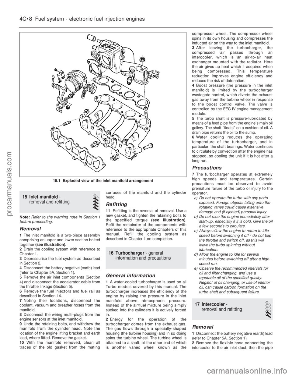
1 The inlet manifold is a two-piece assembly
comprising an upper and lower section bolted
together (see illustration) .
2 Drain the cooling system with reference to
Chapter 1.
3 Depressurise the fuel system as described
in Section 2.
4 Disconnect the battery negative (earth) lead
(refer to Chapter 5A, Section 1).
5 Remove the air inlet components (Section
4) and disconnect the accelerator cable from
the throttle linkage (Section 5).
6 Remove the fuel injectors and fuel rail as
described in Section 14.
7 Noting their locations, disconnect the
coolant, vacuum and breather hoses from the
manifold.
8 Disconnect the wiring multi-plugs from the
engine sensors at the inlet manifold.
9 Undo the retaining bolts, and withdraw the
manifold from the cylinder head. Note the
location of the engine lifting bracket and earth
lead, where fitted. Remove the gasket.
10 With the manifold removed, clean all
traces of the old gasket from the mating surfaces of the manifold and the cylinder
head.
Refitting
11
Refitting is the reversal of removal. Use a
new gasket, and tighten the retaining bolts to
the specified torque (see illustration).
Refit the remainder of the components with
reference to the appropriate Chapters of this
manual. Refill the cooling system as
described in Chapter 1 on completion.
16 Turbocharger - general
information and precautions
General information
1 A water-cooled turbocharger is used on all
Turbo models covered by this manual. The
turbocharger increases the efficiency of the
engine by raising the pressure in the inlet
manifold above atmospheric pressure.
Instead of the air/fuel mixture being simply
sucked into the cylinders it is actively forced
in.
2 Energy for the operation of the
turbocharger comes from the exhaust gas.
The gas flows through a specially-shaped
housing (the turbine housing) and in so doing
spins the turbine wheel. The turbine wheel is
attached to a shaft, at the other end of which
is another vaned wheel known as the compressor wheel. The compressor wheel
spins in its own housing and compresses the
inducted air on the way to the inlet manifold.
3
After leaving the turbocharger, the
compressed air passes through an
intercooler, which is an air-to-air heat
exchanger mounted with the radiator. Here
the air gives up heat which it acquired when
being compressed. This temperature
reduction improves engine efficiency and
reduces the risk of detonation.
4 Boost pressure (the pressure in the inlet
manifold) is limited by the turbocharger
wastegate control, which diverts the exhaust
gas away from the turbine wheel in response
to the boost control valve. The valve is
controlled by the EEC IV engine management
module.
5 The turbo shaft is pressure-lubricated by
means of a feed pipe from the engine’s main oil
gallery. The shaft “floats” on a cushion of oil. A
drain pipe returns the oil to the sump.
6 Water cooling reduces the operating
temperature of the turbocharger, and in
particular, the shaft bearings. Water continues
to circulate by convection after the engine has
stopped, so cooling the unit if it is hot after a
long run.
Precautions
7 The turbocharger operates at extremely
high speeds and temperatures. Certain
precautions must be observed to avoid
premature failure of the turbo or injury to the
operator. a) Do not operate the turbo with any parts
exposed. Foreign objects falling onto the
rotating vanes could cause extensive
damage and (if ejected) personal injury.
b) Do not race the engine immediately after
start-up, especially if it is cold. Give the oil
a few seconds to circulate.
c) Always allow the engine to return to idle
speed before switching it off - do not blip
the throttle and switch off, as this will
leave the turbo spinning without
lubrication.
d) Allow the engine to idle for several
minutes before switching off after a high-
speed run.
e) Observe the recommended intervals for oil and filter changing, and use a
reputable oil of the specified quality.
Neglect of oil changing, or use of inferior
oil, can cause carbon formation on the
turbo shaft and subsequent failure.
17 Intercooler -
removal and refitting
2
Removal
1 Disconnect the battery negative (earth) lead
(refer to Chapter 5A, Section 1).
2 Remove the flexible hose connecting the
intercooler to the air inlet duct, then the pipe
4C•8 Fuel system - electronic fuel injection engines
15.1 Exploded view of the inlet manifold arrangement
1595Ford Fiesta Remakeprocarmanuals.com
http://vnx.su
Page 142 of 296
and flexible hose connecting the turbocharger
to the intercooler (see illustration 4.12) . Use
adhesive tape to seal the turbocharger ports
against the entry of dirt.
3 Unbolt the horn nearest the intercooler.
4 Unbolt the radiator/intercooler assembly
from the bonnet closure panel and the body
crossmember.
5 Move the assembly as far as possible
towards the engine, and unbolt the intercooler
from the radiator; withdraw the intercooler.
Refitting
6 Refitting is the reverse of the removal
procedure, tightening all nuts and bolts to the
specified torque settings, and not forgetting
to unseal the turbocharger openings before
reconnecting the intercooler pipe and hose.
18 Turbocharger boost control valve - removal and refitting
2
Removal
1Disconnect the battery negative (earth) lead
(refer to Chapter 5A, Section 1).
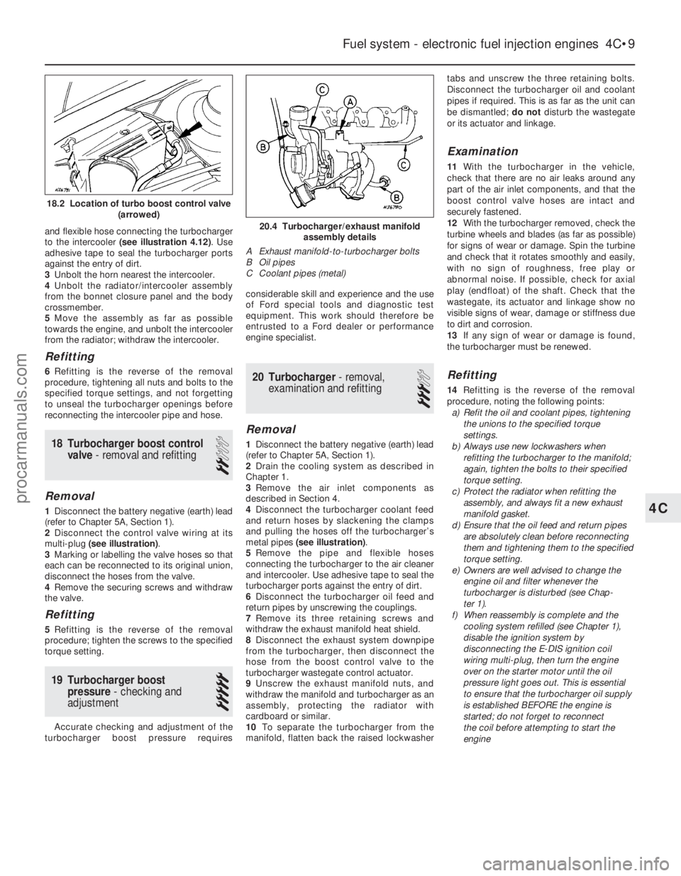
2 Disconnect the control valve wiring at its
multi-plug (see illustration) .
3 Marking or labelling the valve hoses so that
each can be reconnected to its original union,
disconnect the hoses from the valve.
4 Remove the securing screws and withdraw
the valve.
Refitting
5 Refitting is the reverse of the removal
procedure; tighten the screws to the specified
torque setting.
19 Turbocharger boost pressure - checking and
adjustment
5
Accurate checking and adjustment of the
turbocharger boost pressure requires considerable skill and experience and the use
of Ford special tools and diagnostic test
equipment. This work should therefore be
entrusted to a Ford dealer or performance
engine specialist.
20 Turbocharger
- removal,
examination and refitting
3
Removal
1 Disconnect the battery negative (earth) lead
(refer to Chapter 5A, Section 1).
2 Drain the cooling system as described in
Chapter 1.
3 Remove the air inlet components as
described in Section 4.
4 Disconnect the turbocharger coolant feed
and return hoses by slackening the clamps
and pulling the hoses off the turbocharger’s
metal pipes (see illustration) .
5 Remove the pipe and flexible hoses
connecting the turbocharger to the air cleaner
and intercooler. Use adhesive tape to seal the
turbocharger ports against the entry of dirt.
6 Disconnect the turbocharger oil feed and
return pipes by unscrewing the couplings.
7 Remove its three retaining screws and
withdraw the exhaust manifold heat shield.
8 Disconnect the exhaust system downpipe
from the turbocharger, then disconnect the
hose from the boost control valve to the
turbocharger wastegate control actuator.
9 Unscrew the exhaust manifold nuts, and
withdraw the manifold and turbocharger as an
assembly, protecting the radiator with
cardboard or similar.
10 To separate the turbocharger from the
manifold, flatten back the raised lockwasher tabs and unscrew the three retaining bolts.
Disconnect the turbocharger oil and coolant
pipes if required. This is as far as the unit can
be dismantled;
do notdisturb the wastegate
or its actuator and linkage.
Examination
11 With the turbocharger in the vehicle,
check that there are no air leaks around any
part of the air inlet components, and that the
boost control valve hoses are intact and
securely fastened.
12 With the turbocharger removed, check the
turbine wheels and blades (as far as possible)
for signs of wear or damage. Spin the turbine
and check that it rotates smoothly and easily,
with no sign of roughness, free play or
abnormal noise. If possible, check for axial
play (endfloat) of the shaft. Check that the
wastegate, its actuator and linkage show no
visible signs of wear, damage or stiffness due
to dirt and corrosion.
13 If any sign of wear or damage is found,
the turbocharger must be renewed.
Refitting
14 Refitting is the reverse of the removal
procedure, noting the following points: a) Refit the oil and coolant pipes, tightening
the unions to the specified torque
settings.
b) Always use new lockwashers when
refitting the turbocharger to the manifold;
again, tighten the bolts to their specified
torque setting.
c) Protect the radiator when refitting the
assembly, and always fit a new exhaust
manifold gasket.
d) Ensure that the oil feed and return pipes
are absolutely clean before reconnecting
them and tightening them to the specified
torque setting.
e) Owners are well advised to change the engine oil and filter whenever the
turbocharger is disturbed (see Chap-
ter 1).
f) When reassembly is complete and the
cooling system refilled (see Chapter 1),
disable the ignition system by
disconnecting the E-DIS ignition coil
wiring multi-plug, then turn the engine
over on the starter motor until the oil
pressure light goes out. This is essential
to ensure that the turbocharger oil supply
is established BEFORE the engine is
started; do not forget to reconnect
the coil before attempting to start the
engine
Fuel system - electronic fuel injection engines 4C•9
20.4 Turbocharger/exhaust manifold assembly details
A Exhaust manifold-to-turbocharger bolts
B Oil pipes
C Coolant pipes (metal)
4C
1595Ford Fiesta Remake
18.2 Location of turbo boost control valve (arrowed)
procarmanuals.com
http://vnx.su
Page 166 of 296
4If the battery and all connections are in
good condition, check the circuit by
disconnecting the wire from the solenoid
blade terminal. Connect a voltmeter or test
lamp between the wire end and a good earth
(such as the battery negative terminal), and
check that the wire is live when the ignition
switch is turned to the “start” position. If it is,
then the circuit is sound - if not the circuit
wiring can be checked as described in
Chapter 12.
5 The solenoid contacts can be checked by
connecting a voltmeter or test lamp between
the battery positive feed connection on the
starter side of the solenoid, and earth. When
the ignition switch is turned to the “start”
position, there should be a reading or lighted
bulb, as applicable. If there is no reading or
lighted bulb, the solenoid is faulty and should
be renewed.
6 If the circuit and solenoid are proved
sound, the fault must lie in the starter motor.
In this event, it may be possible to have the
starter motor overhauled by a specialist, but
check on the cost of spares before proceeding, as it may prove more economical
to obtain a new or exchange motor.
9 Starter motor
-
removal and refitting
1
Removal
1 Disconnect the battery negative (earth) lead
(refer to Section 1).
2 Chock the rear wheels then jack up the
front of the car and support it on axle stands
(see “Jacking and vehicle support” ). Remove
the front roadwheels.
3 Undo the two retaining nuts, and remove
the starter motor heat shield (where fitted).
4 Prise free the cap, if fitted, then unscrew the
nuts to disconnect the wiring from the
starter/solenoid terminals. Where applicable,
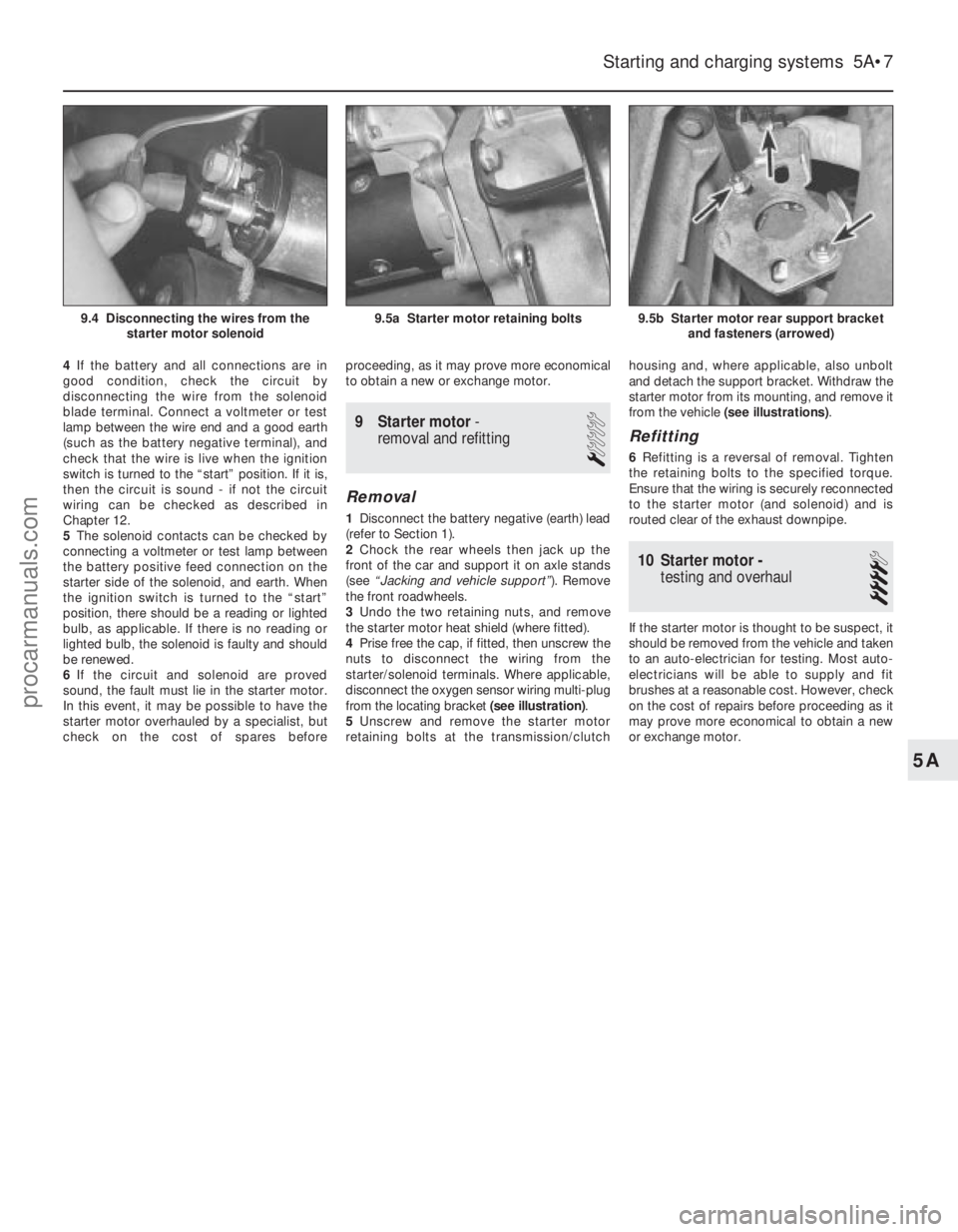
disconnect the oxygen sensor wiring multi-plug
from the locating bracket (see illustration).
5 Unscrew and remove the starter motor
retaining bolts at the transmission/clutch housing and, where applicable, also unbolt
and detach the support bracket. Withdraw the
starter motor from its mounting, and remove it
from the vehicle
(see illustrations) .
Refitting
6Refitting is a reversal of removal. Tighten
the retaining bolts to the specified torque.
Ensure that the wiring is securely reconnected
to the starter motor (and solenoid) and is
routed clear of the exhaust downpipe.
10 Starter motor - testing and overhaul
4
If the starter motor is thought to be suspect, it
should be removed from the vehicle and taken
to an auto-electrician for testing. Most auto-
electricians will be able to supply and fit
brushes at a reasonable cost. However, check
on the cost of repairs before proceeding as it
may prove more economical to obtain a new
or exchange motor.
Starting and charging systems 5A•7
9.5b Starter motor rear support bracket
and fasteners (arrowed)9.5a Starter motor retaining bolts9.4 Disconnecting the wires from thestarter motor solenoid
5A
1595Ford Fiesta Remakeprocarmanuals.com
http://vnx.su