differential FORD FIESTA 1989 Service Repair Manual
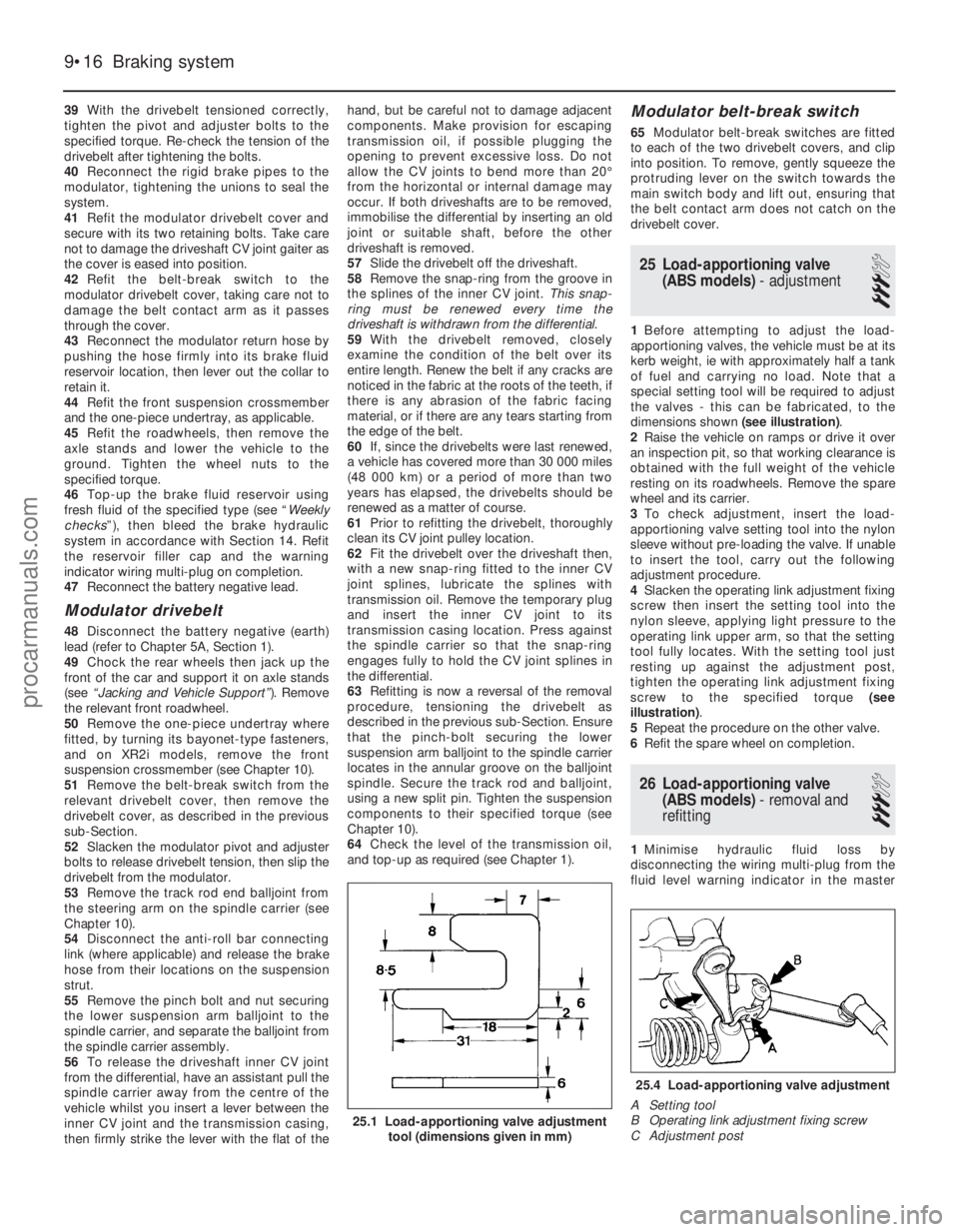
[x] Cancel search | Manufacturer: FORD, Model Year: 1989, Model line: FIESTA, Model: FORD FIESTA 1989Pages: 296, PDF Size: 10.65 MB
Page 79 of 296
25Unscrew the retaining bolt, and detach
the shift rod stabiliser from the transmission.
As it is detached, note the washer located
between the stabiliser and the transmission.
Tie the stabiliser and the shift rod up out of
the way.
Automatic transmission models
26 Unclip and detach the wiring connector
from the starter inhibitor switch (on the
transmission housing).
27 Referring to the relevant Part of Chapter 4
for details, unhook the accelerator (cam plate)
cable from the carburettor or fuel injection unit
(as applicable) at the transmission end of
the cable. Undo the retaining bolt and
detach the cable sheath bracket from the
transmission. Detach the cam plate cable
from the link.
28 Undo the two nuts from the selector cable
bracket which connects it to the lever on the
selector shaft. Disconnect the yoke from the
lever on the selector shaft and the cable from
the lever.
29 Unscrew the union nuts, and disconnect
the oil cooler feed and return pipes from the
transmission. Allow for a certain amount of
spillage, and plug the connections to prevent
the ingress of dirt.
All models
30 Unscrew the retaining nut and withdraw
the Torx-type clamp bolt securing the lower
suspension arm to the spindle carrier on each
side.
31 Refer to Chapter 10 for details, and
detach the right-hand and left-hand track rod
end balljoints from the spindle carriers.
32 On vehicles fitted with the anti-lock
braking system, refer to Chapter 9 and release
the right-hand modulator from its mounting
bracket without disconnecting the rigid brake
pipes or return hose. Tie the modulator
securely to the bulkhead. Additionally, undo
the three bolts securing the modulator
bracket.
33 Insert a suitable lever between the right-
hand driveshaft inner joint and the
transmission housing, and prise free the
driveshaft from the transmission; be prepared
for oil spillage from the transmission case
through the vacated driveshaft aperture. As it
is being prised free, simultaneously pull the
roadwheel outwards on that side, to enable
the driveshaft inboard end to separate
from the transmission. Once it is free,
suspend and support the driveshaft from the
steering gear, to prevent unnecessary strain
being placed on the driveshaft joints.
34 Insert a suitable plastic plug (or if
available, an old driveshaft joint), into the
transmission driveshaft aperture, to
immobilise the gears of the differential unit.
35 Proceed as described above in
paragraphs 33 and 34, and disconnect the
left-hand driveshaft from the transmission.
36 Connect a suitable lift hoist and sling to
the engine, connecting to the lifting eyes. When securely connected, take the weight of
the engine/transmission unit so that the
tension is relieved from the mountings.
37
Undo the retaining bolts and nuts and
detach the right-hand engine mounting from
the vehicle body.
38 Undo the four bolts securing the
transmission bearer to the underside of the
vehicle body. The transmission bearer is
removed with the engine/transmission
assembly.
39 Unscrew the three retaining bolts, and
remove the auxiliary drivebelt cover from
under the crankshaft pulley.
40 The engine/transmission unit should now
be ready for removal from the vehicle. Check
that all of the associated connections and
fittings are disconnected from the engine and
transmission, and positioned out of the way.
41 Enlist the aid of an assistant to help
steady and guide the power unit down
through the engine compartment as it is
removed. If available, position a suitable
engine trolley or crawler board under the
engine/transmission so that when lowered,
the power unit can be withdrawn from the
front end of the vehicle, and then moved to
the area where it is to be cleaned and
dismantled. On automatic transmission
models, particular care must be taken not to
damage the transmission fluid pan (sump)
during the removal and subsequent refitting
processes.
42 Carefully lower the engine and
transmission unit, ensuring that no fittings
become snagged. Detach the hoist and
remove the power unit from under the vehicle.
43 Referring to the relevant Part of Chapter 7,
separate the transmission from the engine.
44 While the engine/transmission is removed,
check the mountings; renew them if they are
worn or damaged. Similarly, check the
condition of all coolant and vacuum hoses
and pipes (see Chapter 1). Components that
are normally hidden can now be checked
properly, and should be renewed if there is
any doubt at all about their condition. Where
the vehicle is fitted with manual transmission,
take the opportunity to inspect the clutch
components (see Chapter 6). It is regarded by
many as good working practice to renew the
clutch assembly as a matter of course,
whenever major engine overhaul work is
carried out. Check also the condition of all
components (such as the transmission oil
seals) disturbed on removal, and renew any
that are damaged or worn.
Refitting
45 Refitting is a reversal of removal, however
note the following additional points:
a) Refer to the applicable Chapters and Sections as for removal.
b) Fit new spring clips to the grooves in the
inboard end of the right- and left-hand
driveshaft joints. Lubricate the splines
with transmission oil prior to fitting. c) Renew the exhaust flange gasket when
reconnecting the exhaust. Ensure that all
wires are routed clear of the exhaust
system and, on catalytic converter
models, ensure that the heat shields are
securely and correctly fitted.
d) Ensure that all earth lead connections are
clean and securely made.
e) Tighten all nuts and bolts to the specified torque.
f) Fit a new oil filter, and refill the engine and transmission with oil, with reference to
Chapter 1.
g) Refill the cooling system with reference to Chapter 1.
h) Refit the alternator and starter motor with reference to Chapter 5A.
i) Where applicable, refit the power steering pump with reference to Chapter 10.
46 When engine and transmission refitting is
complete, refer to the procedures described
in Section 19 before restarting the engine.
5 Engine/transmission -
removal and refitting
(Zetec engines)
3
Warning: Petrol is extremely
flammable, so take extra
precautions when disconnecting
any part of the fuel system.
Don’t smoke, or allow naked flames or
bare light bulbs, in or near the work area,
and don’t work in a garage where a
natural-gas appliance (such as a clothes
dryer or water heater) is installed. If you
spill petrol on your skin, rinse it off
immediately. Have a fire extinguisher rated
for petrol fires handy, and know how to
use it.
Note: Read through the entire Section, as well
as reading the advice in Section 2, before
beginning this procedure. The engine and
transmission are removed as a unit, lowered to
the ground and removed from underneath,
then separated outside the vehicle.
Removal
1 Park the vehicle on firm, level ground, apply
the handbrake firmly, and slacken the nuts
securing both front roadwheels.
2 Depressurise the fuel system as described
in Chapter 4D.
3 Disconnect the battery negative (earth) lead
(refer to Chapter 5A, Section 1).
4 Place protective covers on the wings, then
remove the bonnet (see Chapter 11).
5 Drain the cooling system and the engine oil
(see Chapter 1).
6 Remove the air inlet components and the
complete air cleaner assembly as described in
Chapter 4D.
7 Equalise the pressure in the fuel tank by
removing the filler cap, then release the fuel
feed and return quick-release couplings, and
pull the hoses off the fuel pipes. Plug or cap
all open fittings.
2D•10 Engine removal and overhaul procedures
1595Ford Fiesta Remakeprocarmanuals.com
http://vnx.su
Page 81 of 296
25On automatic transmission models, clean
around the unions, then disconnect the fluid
pipes from the transmission. Plug the
openings in the transmission and the pipe
unions after removal.
26 Refer to Chapter 10 and remove the front
suspension crossmember.
27 Unscrew the nuts to disconnect the
exhaust system front downpipe from the
manifold. Undo the nuts securing the catalytic
converter to the rear part of the exhaust
system, and remove the converter and
downpipe assembly.
28 On vehicles fitted with the anti-lock braking
system, refer to Chapter 9 and release the
right-hand modulator from its mounting
bracket without disconnecting the rigid brake
pipes or return hose. Tie the modulator
securely to the bulkhead. Additionally, undo
the three bolts securing the modulator bracket.
29 Disconnect both anti-roll bar links from
their respective suspension struts, and both
track rod end ball joints from their spindle
carriers (see Chapter 10).
30 Unscrew the retaining nut and withdraw
the Torx-type clamp bolt securing the lower
suspension arm to the spindle carrier on each
side.
31 Insert a suitable lever between the right-
hand driveshaft inner joint and the
transmission housing, and prise free the
driveshaft from the transmission; be prepared
for oil spillage from the transmission case
through the vacated driveshaft aperture. As it
is being prised free, simultaneously pull the
roadwheel outwards on that side to enable the
driveshaft inboard end to separate from the
transmission. Once it is free, suspend and
support the driveshaft from the steering gear,
to prevent unnecessary strain being placed on
the driveshaft joints.
32 Insert a suitable plastic plug (or if
available, an old driveshaft joint), into the
transmission driveshaft aperture, to
immobilise the gears of the differential unit.
33 Proceed as described above in
paragraphs 31 and 32, and disconnect the
left-hand driveshaft from the transmission.
34 Remove the oil filter, referring to Chapter 1
if necessary.
35 Connect a suitable lift hoist and sling to
the engine, connecting to the lift eyes. When
securely connected, take the weight of the
engine/transmission unit so that the tension is
relieved from the mountings.
36 Unbolt the engine rear right-hand
mounting from the body (one bolt in the wheel
arch, one nut in the engine compartment),
then unbolt the engine front right-hand
mounting from the alternator mounting
bracket. Unbolt the transmission bearer from
the underbody.
37 The engine/transmission unit should now
be hanging on the hoist only, with all
components which connect it to the rest of
the vehicle disconnected or removed, and
secured well clear of the unit. Make a final
check that this is the case. 38
Lower the engine/transmission to the
ground, and withdraw it from under the
vehicle.
39 Referring to the relevant Part of Chapter 7,
separate the transmission from the engine.
40 While the engine/transmission is removed,
check the mountings; renew them if they are
worn or damaged. Similarly, check the
condition of all coolant and vacuum hoses
and pipes (see Chapter 1); components that
are normally hidden can now be checked
properly, and should be renewed if there is
any doubt at all about their condition. Where
the vehicle is fitted with manual transmission,
take the opportunity to overhaul the clutch
components (see Chapter 6). It is regarded by
many as good working practice to renew the
clutch assembly as a matter of course,
whenever major engine overhaul work is
carried out. Check also the condition of all
components (such as the transmission oil
seals) disturbed on removal, and renew any
that are damaged or worn.
Refitting
41 Refitting is a reversal of removal, however
note the following additional points:
a) Refer to the applicable Chapters and Sections as for removal.
b) Fit new spring clips to the grooves in the
inboard end of the right- and left-hand
driveshaft joints. Lubricate the splines
with transmission oil prior to fitting.
c) Renew the exhaust flange gaskets when reconnecting the exhaust. Ensure that all
wires are routed clear of the exhaust
system, and that the heat shields are
securely and correctly fitted.
d) Ensure that all earth lead connections are
clean and securely made.
e) Tighten all nuts and bolts to the specified
torque.
f) Fit a new oil filter, and refill the engine and transmission with oil, with reference to
Chapter 1.
g) Refill the cooling system with reference to
Chapter 1.
h) Bleed the power steering system with reference to Chapter 10.
42 When engine and transmission refitting is
complete, refer to the procedures described
in Section 19 before restarting the engine.
6 Engine overhaul - preliminary information
It is much easier to dismantle and work on
the engine if it is mounted on a portable
engine stand. These stands can often be hired
from a tool hire shop. Before the engine is
mounted on a stand, the flywheel/driveplate
should be removed so that the stand bolts
can be tightened into the end of the cylinder
block/crankcase. If a stand is not available, it is possible to
dismantle the engine with it suitably supported on a sturdy, workbench or on the
floor. Be careful not to tip or drop the engine
when working without a stand.
If you intend to obtain a reconditioned
engine, all ancillaries must be removed first, to
be transferred to the replacement engine (just
as they will if you are doing a complete engine
overhaul yourself). These components include
the following:
a) Alternator/power steering pump and
mounting brackets.
b) DIS/E-DIS ignition coil unit (and mounting
bracket), distributor, HT leads and spark
plugs.
c) The thermostat and housing cover.
d) Carburettor/fuel injection system
components.
e) Inlet and exhaust manifolds.
f) Oil filter.
g) Fuel pump.
h) Engine mountings.
i) Flywheel/driveplate.
j) Water pump.
Note: When removing the external
components from the engine, pay close
attention to details that may be helpful or
important during refitting. Note the fitted
positions of gaskets, seals, washers, bolts and
other small items. If you are obtaining a “short” engine
(cylinder block/crankcase, crankshaft, pistons
and connecting rods all assembled), then the
cylinder head, timing chain/belt (together with
tensioner, tensioner and idler pulleys and
covers) sump and oil pump will have to be
removed also. If a complete overhaul is planned, the
engine can be dismantled in the order given
below, referring to Part A, B or C of this
Chapter unless otherwise stated.
a) Inlet and exhaust manifolds.
b) Timing chain/belt, tensioner and
sprockets.
c) Cylinder head.
d) Flywheel/driveplate.
e) Sump.
f) Oil pump.
g) Pistons (with connecting rods).
h) Crankshaft.
i) Camshaft and tappets (HCS engines).
7 Cylinder head - dismantling
4
Note:New and reconditioned cylinder heads
are available from the manufacturers, and from
engine overhaul specialists. Due to the fact
that some specialist tools are required for the
dismantling and inspection procedures, and
new components may not be readily available,
it may be more practical and economical for
the home mechanic to purchase a
reconditioned head, rather than to dismantle,
inspect and recondition the original head.
1 Remove the cylinder head as described in
Part A, B or C of this Chapter (as applicable).
2D•12 Engine removal and overhaul procedures
1595Ford Fiesta Remakeprocarmanuals.com
http://vnx.su
Page 191 of 296
39With the drivebelt tensioned correctly,
tighten the pivot and adjuster bolts to the
specified torque. Re-check the tension of the
drivebelt after tightening the bolts.
40 Reconnect the rigid brake pipes to the
modulator, tightening the unions to seal the
system.
41 Refit the modulator drivebelt cover and
secure with its two retaining bolts. Take care
not to damage the driveshaft CV joint gaiter as
the cover is eased into position.
42 Refit the belt-break switch to the
modulator drivebelt cover, taking care not to
damage the belt contact arm as it passes
through the cover.
43 Reconnect the modulator return hose by
pushing the hose firmly into its brake fluid
reservoir location, then lever out the collar to
retain it.
44 Refit the front suspension crossmember
and the one-piece undertray, as applicable.
45 Refit the roadwheels, then remove the
axle stands and lower the vehicle to the
ground. Tighten the wheel nuts to the
specified torque.
46 Top-up the brake fluid reservoir using
fresh fluid of the specified type (see “ Weekly
checks ”), then bleed the brake hydraulic
system in accordance with Section 14. Refit
the reservoir filler cap and the warning
indicator wiring multi-plug on completion.
47 Reconnect the battery negative lead.
Modulator drivebelt
48Disconnect the battery negative (earth)
lead (refer to Chapter 5A, Section 1).
49 Chock the rear wheels then jack up the
front of the car and support it on axle stands
(see “Jacking and Vehicle Support” ). Remove
the relevant front roadwheel.
50 Remove the one-piece undertray where
fitted, by turning its bayonet-type fasteners,
and on XR2i models, remove the front
suspension crossmember (see Chapter 10).
51 Remove the belt-break switch from the
relevant drivebelt cover, then remove the
drivebelt cover, as described in the previous
sub-Section.
52 Slacken the modulator pivot and adjuster
bolts to release drivebelt tension, then slip the
drivebelt from the modulator.
53 Remove the track rod end balljoint from
the steering arm on the spindle carrier (see
Chapter 10).
54 Disconnect the anti-roll bar connecting
link (where applicable) and release the brake
hose from their locations on the suspension
strut.
55 Remove the pinch bolt and nut securing
the lower suspension arm balljoint to the
spindle carrier, and separate the balljoint from
the spindle carrier assembly.
56 To release the driveshaft inner CV joint
from the differential, have an assistant pull the
spindle carrier away from the centre of the
vehicle whilst you insert a lever between the
inner CV joint and the transmission casing,
then firmly strike the lever with the flat of the hand, but be careful not to damage adjacent
components. Make provision for escaping
transmission oil, if possible plugging the
opening to prevent excessive loss. Do not
allow the CV joints to bend more than 20°
from the horizontal or internal damage may
occur. If both driveshafts are to be removed,
immobilise the differential by inserting an old
joint or suitable shaft, before the other
driveshaft is removed.
57
Slide the drivebelt off the driveshaft.
58 Remove the snap-ring from the groove in
the splines of the inner CV joint. This snap-
ring must be renewed every time the
driveshaft is withdrawn from the differential.
59 With the drivebelt removed, closely
examine the condition of the belt over its
entire length. Renew the belt if any cracks are
noticed in the fabric at the roots of the teeth, if
there is any abrasion of the fabric facing
material, or if there are any tears starting from
the edge of the belt.
60 If, since the drivebelts were last renewed,
a vehicle has covered more than 30 000 miles
(48 000 km) or a period of more than two
years has elapsed, the drivebelts should be
renewed as a matter of course.
61 Prior to refitting the drivebelt, thoroughly
clean its CV joint pulley location.
62 Fit the drivebelt over the driveshaft then,
with a new snap-ring fitted to the inner CV
joint splines, lubricate the splines with
transmission oil. Remove the temporary plug
and insert the inner CV joint to its
transmission casing location. Press against
the spindle carrier so that the snap-ring
engages fully to hold the CV joint splines in
the differential.
63 Refitting is now a reversal of the removal
procedure, tensioning the drivebelt as
described in the previous sub-Section. Ensure
that the pinch-bolt securing the lower
suspension arm balljoint to the spindle carrier
locates in the annular groove on the balljoint
spindle. Secure the track rod and balljoint,
using a new split pin. Tighten the suspension
components to their specified torque (see
Chapter 10).
64 Check the level of the transmission oil,
and top-up as required (see Chapter 1).
Modulator belt-break switch
65 Modulator belt-break switches are fitted
to each of the two drivebelt covers, and clip
into position. To remove, gently squeeze the
protruding lever on the switch towards the
main switch body and lift out, ensuring that
the belt contact arm does not catch on the
drivebelt cover.
25 Load-apportioning valve (ABS models) - adjustment
3
1Before attempting to adjust the load-
apportioning valves, the vehicle must be at its
kerb weight, ie with approximately half a tank
of fuel and carrying no load. Note that a
special setting tool will be required to adjust
the valves - this can be fabricated, to the
dimensions shown (see illustration).
2 Raise the vehicle on ramps or drive it over
an inspection pit, so that working clearance is
obtained with the full weight of the vehicle
resting on its roadwheels. Remove the spare
wheel and its carrier.
3 To check adjustment, insert the load-
apportioning valve setting tool into the nylon
sleeve without pre-loading the valve. If unable
to insert the tool, carry out the following
adjustment procedure.
4 Slacken the operating link adjustment fixing
screw then insert the setting tool into the
nylon sleeve, applying light pressure to the
operating link upper arm, so that the setting
tool fully locates. With the setting tool just
resting up against the adjustment post,
tighten the operating link adjustment fixing
screw to the specified torque (see
illustration) .
5 Repeat the procedure on the other valve.
6 Refit the spare wheel on completion.
26 Load-apportioning valve
(ABS models) - removal and
refitting
3
1 Minimise hydraulic fluid loss by
disconnecting the wiring multi-plug from the
fluid level warning indicator in the master
9•16 Braking system
25.4 Load-apportioning valve adjustment
A Setting tool
B Operating link adjustment fixing screw
C Adjustment post
25.1 Load-apportioning valve adjustment tool (dimensions given in mm)
1595Ford Fiesta Remakeprocarmanuals.com
http://vnx.su
Page 283 of 296
1595 Ford Fiesta Remake
Fault findingREF•17
REF
Fuel and exhaust systems
Excessive fuel consumption
m
mUnsympathetic driving style, or adverse conditions.
m
m Air filter element dirty or clogged (Chapter 1).
m
m Engine management system fault (Chapters 1, 4A, 4B, 4C, 4D, 4E
or 5B).
m m Tyres under-inflated ( “Weekly Checks”).
Fuel leakage and/or fuel odour
m
mDamaged or corroded fuel tank, pipes or connections (Chapter 1).
m
m Charcoal canister and/or connecting pipes leaking (Chapters 1
and 4E).
Excessive noise or fumes from exhaust system
m mLeaking exhaust system or manifold joints (Chapters 1 or 4E).
m
m Leaking, corroded or damaged silencers or pipe (Chapters 1 or 4E).
m
m Broken mountings, causing body or suspension contact (Chap-
ters 1 or 4E).
Clutch
Pedal travels to floor - no pressure or very little
resistance
m mBroken clutch cable (Chapter 6).
m
m Faulty clutch automatic adjuster (Chapter 6).
m
m Broken clutch release bearing or fork (Chapter 6).
m
m Broken diaphragm spring in clutch pressure plate (Chapter 6).
Clutch fails to disengage (unable to select gears)
m
mFaulty clutch automatic adjuster (Chapter 6).
m
m Clutch disc sticking on transmission input shaft splines (Chapter 6).
m
m Clutch disc sticking to flywheel or pressure plate (Chapter 6).
m
m Faulty pressure plate assembly (Chapter 6).
m
m Clutch release mechanism worn or incorrectly assembled (Chapter 6).
Clutch slips (engine speed increases, with no
increase in vehicle speed)
m mFaulty clutch automatic adjuster (Chapter 6).
m
m Clutch disc linings excessively worn (Chapter 6).
m
m Clutch disc linings contaminated with oil or grease (Chapter 6).
m
m Faulty pressure plate or weak diaphragm spring (Chapter 6).
Judder as clutch is engaged
m
mClutch disc linings contaminated with oil or grease (Chapter 6).
m
m Clutch disc linings excessively worn (Chapter 6).
m
m Clutch cable sticking or frayed (Chapter 6).
m
m Faulty or distorted pressure plate or diaphragm spring (Chapter 6).
m
m Worn or loose engine/transmission mountings (Chapters 2A, 2B
or 2C).
m m Clutch disc hub or transmission input shaft splines worn (Chap-
ter 6).
Noise when depressing or releasing clutch pedal
m mWorn clutch release bearing (Chapter 6).
m
m Worn or dry clutch pedal bushes (Chapter 6).
m
m Faulty pressure plate assembly (Chapter 6).
m
m Pressure plate diaphragm spring broken (Chapter 6).
m
m Broken clutch disc cushioning springs (Chapter 6).
Manual transmission
Noisy in neutral with engine running
m
mInput shaft bearings worn (noise apparent with clutch pedal
released, but not when depressed) (Chapter 7A).*
m m Clutch release bearing worn (noise apparent with clutch pedal
depressed, possibly less when released) (Chapter 6).
Noisy in one particular gear
m mWorn, damaged or chipped gear teeth (Chapter 7A).*
Difficulty engaging gears
m
mClutch fault (Chapter 6).
m
m Worn or damaged gear linkage (Chapter 7A).
m
m Incorrectly-adjusted gear linkage (Chapter 7A).
m
m Worn synchroniser assemblies (Chapter 7A).*
Vibration
m
mLack of oil (Chapter 1).
m
m Worn bearings (Chapter 7A).*
Jumps out of gear
m
mWorn or damaged gear linkage (Chapter 7A).
m
m Incorrectly-adjusted gear linkage (Chapter 7A).
m
m Worn synchroniser assemblies (Chapter 7A).*
m
m Worn selector forks (Chapter 7A).*
Lubricant leaks
m
mLeaking differential side gear oil seal (Chapter 7A).
m
m Leaking housing joint (Chapter 7A).*
m
m Leaking input shaft oil seal (Chapter 7A).*
m
m Leaking selector shaft oil seal (Chapter 7A).
m
m Leaking speedometer drive pinion O-ring (Chapter 7A).
* Although the corrective action necessary to remedy the symptoms
described is beyond the scope of the home mechanic, the above
information should be helpful in isolating the cause of the condition,
so that the owner can communicate clearly with a professional
mechanic.
procarmanuals.com
http://vnx.su
Page 284 of 296
1595 Ford Fiesta Remake
REF•18Fault finding
Braking system
Note:Before assuming that a brake problem exists, make sure that the
tyres are in good condition and correctly inflated, that the front wheel\
alignment is correct, and that the vehicle is not loaded with weight in \
an
unequal manner. Apart from checking the condition of all pipe and
hose connections, any faults occurring on the Anti-lock Braking System
(ABS) should be referred to a Ford dealer for diagnosis.
Vehicle pulls to one side under braking
m m Worn, defective, damaged or contaminated front or rear brake
pads/shoes on one side (Chapter 1).
m m Seized or partially-seized front or rear brake caliper/wheel cylinder
piston (Chapter 9).
m m A mixture of brake pad/shoe lining materials fitted between sides
Chapter 1).
m m Brake caliper mounting bolts loose (Chapter 9).
m
m Rear brake backplate mounting bolts loose (Chapter 9).
m
m Worn or damaged steering or suspension components (Chap-
ter 10).
Noise (grinding or high-pitched squeal) when
brakes applied
m mBrake pad or shoe friction lining material worn down to metal
backing Chapter 1).
m m Excessive corrosion of brake disc or drum (may be apparent after
the vehicle has been standing for some time) (Chapter 1).
Excessive brake pedal travel
m mInoperative rear brake self-adjust mechanism (Chapter 9).
m
m Faulty master cylinder (Chapter 9).
m
m Air in hydraulic system (Chapter 9).
Rear wheels locking under normal braking
m
mRear brake shoe linings contaminated (Chapter 1).
m
m Faulty brake pressure regulator (Chapter 9).
Brake pedal feels spongy when depressed
m
mAir in hydraulic system (Chapter 9).
m
m Deteriorated flexible rubber brake hoses (Chapter 9).
m
m Master cylinder mounting nuts loose (Chapter 9).
m
m Faulty master cylinder (Chapter 9).
Excessive brake pedal effort required to stop
vehicle
m mFaulty vacuum servo unit (Chapter 9).
m
m Disconnected, damaged or insecure brake servo vacuum hose
(Chapter 9).
m m Primary or secondary hydraulic circuit failure (Chapter 9).
m
m Seized brake caliper or wheel cylinder piston(s) (Chapter 9).
m
m Brake pads or brake shoes incorrectly fitted (Chapter 9).
m
m Incorrect grade of brake pads or brake shoes fitted (Chapter 1).
m
m Brake pads or brake shoe linings contaminated (Chapter 1).
Judder felt through brake pedal or steering wheel
when braking
m mExcessive run-out or distortion of front discs or rear drums
Chapter 9).
m m Brake pad or brake shoe linings worn (Chapter 1).
m
m Brake caliper or rear brake backplate mounting bolts loose
(Chapter 9).
m m Wear in suspension or steering components or mountings
(Chapter 10).
Brakes binding
m mSeized brake caliper or wheel cylinder piston(s) (Chapter 9).
m
m Faulty handbrake mechanism (Chapter 9).
m
m Faulty master cylinder (Chapter 9).
Automatic transmission
Note: Due to the complexity of the automatic transmission, it is difficult
for the home mechanic to properly diagnose and service this unit. For
problems other than the following, the vehicle should be taken to a
dealer service department or automatic transmission specialist.
Fluid leakage
m m Automatic transmission fluid is usually deep red in colour. Fluid
leaks should not be confused with engine oil, which can easily be
blown onto the transmission by airflow.
m m To determine the source of a leak, first remove all built-up dirt and
grime from the transmission housing and surrounding areas, using
a degreasing agent, or by steam-cleaning. Drive the vehicle at low
speed, so airflow will not blow the leak far from its source. Raise
and support the vehicle, and determine where the leak is coming
from. The following are common areas of leakage:
a) Transmission fluid sump (Chapters 1 and 7B).
b) Dipstick tube (Chapters 1 and 7B).
c) Transmission-to-fluid cooler pipes/unions (Chapter 7B).
d) Speedometer drive pinion O-ring.
e) Differential output fluid seals (Chapter 7B).
Transmission fluid brown, or has burned smell
m m Transmission fluid level low, or fluid in need of renewal (Chapter 1).\
Engine will not start in any gear, or starts in gears
other than Park or Neutral
m mStarter inhibitor switch faulty (Chapter 7B).
m
m Incorrect selector cable adjustment (Chapter 7B).
General gear selection problems
m
mChapter 7B deals with checking and adjusting the selector cable
on automatic transmissions. The following are common problems
which may be caused by a poorly-adjusted cable:
a) Engine starting in gears other than Park or Neutral.
b) Indicator on gear selector lever pointing to a gear other than the
one actually being used.
c) Vehicle moves when in Park or Neutral.
d) Poor gear shift quality or erratic gear changes.
Refer to Chapter 7B for the selector cable adjustment procedure.
Transmission will not downshift (kickdown) with
accelerator pedal fully depressed
m m Low transmission fluid level (Chapter 1).
m
m Incorrect selector cable adjustment (Chapter 7B).
m
m Engine management system fault (Chapters 1, 4A, 4B, 4C, 4D, 4E
or 5B).
Transmission slips, is noisy, or has no drive in
forward or reverse gears
m mThere are many probable causes for the above problems, but the
home mechanic should be concerned with only one possibility -
fluid level. Before taking the vehicle to a dealer or transmission
specialist, check the fluid level and condition of the fluid as
described in Chapter 1. Correct the fluid level as necessary, or
change the fluid if needed. If the problem persists, professional
help will be necessary.
procarmanuals.com
http://vnx.su
Page 288 of 296
1595 Ford Fiesta Remake
REF•22Glossary of technical terms
A
ABS (Anti-lock brake system)A system,
usually electronically controlled, that senses
incipient wheel lockup during braking and
r elieves hydraulic pressure at wheels that are
about to skid.
Air bag An inflatable bag hidden in the
steering wheel (driver’s side) or the dash or
glovebox (passenger side). In a head-on
collision, the bags inflate, preventing the
driver and front passenger from being thrown
forwar d into the steering wheel or windscreen.
Air cleaner A metal or plastic housing,
containing a filter element, which removes
dust and dirt from the air being drawn into the
engine.
Air filter element The actual filter in an air
cleaner system, usually manufactured fr om
pleated paper and requiring renewal at regular
intervals.
Allen key A hexagonal wrench which fits into
a recessed hexagonal hole.
Alligator clip A long-nosed spring-loaded
metal clip with meshing teeth. Used to make
temporary electrical connections.
Alternator A component in the electrical
system which converts mechanical energy
fr om a drivebelt into electrical energy to
char ge the battery and to operate the starting
system, ignition system and electrical
accessories.
Amper e (amp) A unit of measurement for the
flow of electric current. One amp is the
amount of current produced by one volt
acting through a resistance of one ohm.
Anaer obic sealer A substance used to
pr event bolts and screws from loosening.
Anaer obic means that it does not require
oxygen for activation. The Loctite brand is
widely used.
Antifreeze A substance (usually ethylene
glycol) mixed with water, and added to a
vehicle’ s cooling system, to prevent freezing
of the coolant in winter. Antifreeze also
contains chemicals to inhibit corrosion and
the formation of rust and other deposits that would tend to clog the radiator and coolant
passages and reduce cooling efficiency.
Anti-seize compound A coating that
r educes the risk of seizing on fasteners that
ar e subjected to high temperatures, such as
exhaust manifold bolts and nuts.
Asbestos A natural fibrous mineral with great
heat resistance, commonly used in the
composition of brake friction materials.
Asbestos is a health hazard and the dust
cr eated by brake systems should never be
inhaled or ingested.
Axle A shaft on which a wheel revolves, or
which revolves with a wheel. Also, a solid
beam that connects the two wheels at one
end of the vehicle. An axle which also
transmits power to the wheels is known as a
live axle.
Axleshaft A single rotating shaft, on either
side of the differential, which delivers power
fr om the final drive assembly to the drive
wheels. Also called a driveshaft or a halfshaft.
BBall bearing An anti-friction bearing
consisting of a hardened inner and outer race
with hardened steel balls between two races. Bearing
The curved surface on a shaft or in a
bor e, or the part assembled into either, that
permits relative motion between them with
minimum wear and friction.
Big-end bearing The bearing in the end of
the connecting rod that’s attached to the crankshaft.
Bleed nipple A valve on a brake wheel
cylinder , caliper or other hydraulic component
that is opened to purge the hydraulic system
of air. Also called a bleed screw.
Brake bleeding Procedure for removing air
fr om lines of a hydraulic brake system.
Brake disc The component of a disc brake
that rotates with the wheels.
Brake drum The component of a drum brake
that rotates with the wheels.
Brake linings The friction material which
contacts the brake disc or drum to retard the
vehicle’ s speed. The linings are bonded or
riveted to the brake pads or shoes.
Brake pads The replaceable friction pads
that pinch the brake disc when the brakes are
applied. Brake pads consist of a friction
material bonded or riveted to a rigid backing
plate.
Brake shoe The crescent-shaped carrier to
which the brake linings are mounted and
which forces the lining against the rotating drum during braking.
Braking systems For more information on
braking systems, consult the Haynes
Automotive Brake Manual .
Br eaker bar A long socket wrench handle
pr oviding greater leverage.
Bulkhead The insulated partition between
the engine and the passenger compartment.
CCaliper The non-rotating part of a disc-brake
assembly that straddles the disc and carries
the brake pads. The caliper also contains the
hydraulic components that cause the pads to
pinch the disc when the brakes are applied. A
caliper is also a measuring tool that can be set
to measure inside or outside dimensions of an
object.
Brake bleeding
Bearing
Axle assembly
Anti-seize compound
Alter nator (exploded view)
Air filter
procarmanuals.com
http://vnx.su
Page 291 of 296
1595 Ford Fiesta Remake
Glossary of technical termsREF•25
REF
JJump startStarting the engine of a vehicle
with a discharged or weak battery by
attaching jump leads from the weak battery to
a charged or helper battery.
LLoad Sensing Proportioning Valve (LSPV) A
brake hydraulic system control valve that
works like a proportioning valve, but also
takes into consideration the amount of weight
carried by the rear axle.
Locknut A nut used to lock an adjustment
nut, or other threaded component, in place.
For example, a locknut is employed to keep
the adjusting nut on the rocker arm in
position.
Lockwasher A form of washer designed to
pr event an attaching nut from working loose.
MMacPherson strut A type of front
suspension system devised by Earle
MacPherson at Ford of England. In its original
form, a simple lateral link with the anti-roll bar
cr eates the lower control arm. A long strut - an
integral coil spring and shock absorber - is
mounted between the body and the steering
knuckle. Many modern so-called MacPherson
strut systems use a conventional lower A-arm
and don’t rely on the anti-roll bar for location. Multimeter An electrical test instrument with
the capability to measure voltage, current and
resistance.
NNOx Oxides of Nitrogen. A common toxic
pollutant emitted by petrol and diesel engines
at higher temperatures.
OOhm The unit of electrical resistance. One
volt applied to a resistance of one ohm will
pr oduce a current of one amp.
Ohmmeter An instrument for measuring
electrical resistance.
O-ring A type of sealing ring made of a
special rubber-like material; in use, the O-ring
is compressed into a groove to provide the
sealing action. Overhead cam (ohc) engine
An engine with
the camshaft(s) located on top of the cylinder
head(s).
Overhead valve (ohv) engine An engine with
the valves located in the cylinder head, but
with the camshaft located in the engine block.
Oxygen sensor A device installed in the
engine exhaust manifold, which senses the
oxygen content in the exhaust and converts
this information into an electric current. Also
called a Lambda sensor.
PPhillips screw A type of screw head having a
cr oss instead of a slot for a corresponding
type of screwdriver.
Plastigage A thin strip of plastic thread,
available in different sizes, used for measuring clearances. For example, a strip of Plastigage
is laid across a bearing journal. The parts areassembled and dismantled; the width of the
crushed strip indicates the clearance between
jour nal and bearing.
Pr opeller shaft The long hollow tube with
universal joints at both ends that carries
power from the transmission to the differential on front-engined rear wheel drive vehicles.
Pr oportioning valve A hydraulic control
valve which limits the amount of pressure to
the rear brakes during panic stops to prevent
wheel lock-up.
RRack-and-pinion steering A steering system
with a pinion gear on the end of the steering
shaft that mates with a rack (think of a geared
wheel opened up and laid flat). When the
steering wheel is turned, the pinion turns,
moving the rack to the left or right. This
movement is transmitted through the track
r ods to the steering arms at the wheels.
Radiator A liquid-to-air heat transfer device
designed to reduce the temperature of the
coolant in an internal combustion engine
cooling system.
Refrigerant Any substance used as a heat
transfer agent in an air-conditioning system.
R-12 has been the principle refrigerant for
many years; recently, however, manufacturers
have begun using R-134a, a non-CFC
substance that is considered less harmful to the ozone in the upper atmosphere.
Rocker arm
A lever arm that rocks on a shaft
or pivots on a stud. In an overhead valve
engine, the rocker arm converts the upward
movement of the pushrod into a downward
movement to open a valve.
Rotor In a distributor, the rotating device
inside the cap that connects the centre
electr ode and the outer terminals as it turns,
distributing the high voltage from the coil
secondary winding to the proper spark plug.
Also, that part of an alternator which rotates
inside the stator. Also, the rotating assembly
of a turbocharger, including the compressor
wheel, shaft and turbine wheel.
Runout The amount of wobble (in-and-out
movement) of a gear or wheel as it’ s rotated.
The amount a shaft rotates “out-of-true.” The
out-of-r ound condition of a rotating part.
SSealant A liquid or paste used to prevent
leakage at a joint. Sometimes used in
conjunction with a gasket.
Sealed beam lamp An older headlight design
which integrates the reflector, lens and
filaments into a hermetically-sealed one-piece
unit. When a filament burns out or the lens
cracks, the entire unit is simply replaced.
Serpentine drivebelt A single, long, wide
accessory drivebelt that’s used on some
newer vehicles to drive all the accessories,
instead of a series of smaller, shorter belts.
Serpentine drivebelts are usually tensioned by
an automatic tensioner.
Shim Thin spacer, commonly used to adjust
the clearance or relative positions between
two parts. For example, shims inserted into or
under bucket tappets control valve
clearances. Clearance is adjusted by
changing the thickness of the shim.
Slide hammer A special puller that screws
into or hooks onto a component such as a
shaft or bearing; a heavy sliding handle on the
shaft bottoms against the end of the shaft to
knock the component free.
Sprocket A tooth or projection on the
periphery of a wheel, shaped to engage with a
chain or drivebelt. Commonly used to refer to
the sprocket wheel itself.
Starter inhibitor switch On vehicles with an
O-ring
Serpentine drivebelt
Plastigage
procarmanuals.com
http://vnx.su
Page 293 of 296
1595 Ford Fiesta Remake
IndexREF•27
REF
Note: References throughout this index relate to Chapter•page number
A
Accelerator cable -4A•4, 4B•4, 4C•4, 4D•3
Accelerator pedal - 4A•4, 4B•4, 4C•4, 4D•3
Accelerator pump - 4A•8
Acknowledgements - 0•4
Aerial - 12•16
Air bags - 0•5, 12•17
Air cleaner - 1•22, 1•23, 4A•3, 4B•4, 4C•3,
4D•3, 4E•5
Air temperature control system - 1•23,
4B•8, 4C•7, 4D•6
Alarm system - 12•17, REF• 5
Alternator - 5A•4
Anti-lock braking system (ABS) - 9•11,
9•14, 9•16
Anti-roll bar - 10•7, 10•11
Anti-theft alarm system - 12•17, REF•5
Antifreeze - 0•12, 0•17, 1•21, 1•22, 3•2
Asbestos - 0•5
ATF - 0•17, 1•18, 1•24
Automatic choke - 4A•16, 4A•17
Automatic transmission -2A•10, 2B•13,
2C•15, 2D•6, 2D•8, 2D•10, 7B•1 et seq,
12 •6, 12 •8
Automatic transmission fault finding - REF• 18
Automatic transmission fluid - 0•17, 1•18,
1•24
Auxiliary lights - 12•7, 12•10
Axle - 10•10
B
Backfire - REF•16
Backrest - 11•17
Ballast resistor - 4B•9
Balljoint - 10•17
Battery - 0•5, 0•14, 5A•2, 5A•3
Battery fault - REF•20
Big-end bearings - 2D•21, 2D•24
Bleeding braking system - 9•10, 9•11
Bleeding power steering - 10•17
Body electrical systems -1•18, 12 •1et seq,
REF• 11
Body electrical system fault finding - 5A•2,
12 •3, REF •20
Bodywork and fittings -1•18, 11 •1et seq,
REF• 13
Bonnet - 1•18, 11•4,11•5
Boot - 1•16
Boots - 8•3, 8•4, 10 •15
Brake fluid - 0•13, 0•17, 1•26, 12 •6
Braking system -1•17, 9•1 et seq, 12•6,
REF• 10, REF•11, REF• 12
Braking system fault finding - REF•18 Bulbs -
0•16, 12 •7,12•8
Bumpers - 11•7, 11•8
Burning - 0•5
Buying spare parts - REF•5
C
Cables -4A•4, 4B•4, 4C•4, 4D•3, 6•1, 7B•2,
9•12, 9•13, 12 •12
Calipers - 9•3
Camshaft - 2B•6, 2B•7, 2C•7, 2C•8, 2D•16
Camshaft position sensor - 4D•6
Carburettor - 4A•7, 4A•8, 4A•9, 4A•11,
4A•13, 4A•14, 4A•15, 4A•17, 4A•18
Carpets - 11•2
Cassette player - 12•15, REF •5
Catalytic converter - 4E•2, 4E•5
Centre console - 11•20, 12 •5
Charcoal canister - 4E•6
Charging system - 5A•3
Choke - 4A•4, 4A•16, 4A•17
Cigarette lighter - 12•9, 12 •12
Clock - 12•8, 12•12
Clutch -1•18, 6•1 et seq
Clutch fault finding - REF•17
Coil - 5B•4
Compression test - 2A•3, 2B•3, 2C•3
Connecting rods - 2D•17, 2D•24, 2D•25
Console - 11•20, 12•5
Contents - 0•2
Conversion factors - REF•6
Coolant - 0•12, 0•17, 1•21, 1•22, 3•2
Coolant pump - 3•7
Coolant temperature sensor - 4B•8, 4C•7,
4D•6
Cooling ,heating and ventilation systems -
3•1 et seq
Cooling system fault finding - REF•16
Courtesy light - 12•6, 12•9
Crankcase - 2D•19
Crankcase ventilation system - 1•24
Crankshaft - 2A•6, 2A•9, 2B•4, 2B•6,
2B•12, 2C•4, 2C•7, 2C•14, 2D•18,
2D•22, 2D•24
Crankshaft position sensor - 4B•8, 4C•7,
4D•6, 5B•5
Crossmember - 10•7
Crushing - 0•5
Cushion - 11•17
CV joint - 1•16, 8•3, 8•4
CVH and PTE engine in-car repair
procedures -2B•1 et seq
Cylinder block - 2D•19
Cylinder head - 2A•4, 2A•5, 2B•4, 2B•9,
2C•3, 2C•10, 2D•12, 2D•14, 2D•15
D
Dents in bodywork - 11•2
Depressurising fuel system - 4B•3, 4C•3,
4D•2
Differential - 7A•3, 7B•3
Dimensions - REF•1
Direction indicators - 12•7, 12•9, 12•10
Discs - 9•4
Distributor - 1•20, 5B•5, 5B•6, 5B•7
Doors - 1•18, 11• 6,11•9, 11 •10,,11 •11,
11 •13, 11•14, 11•15, REF •11
Drip rail moulding - 11•5
Drivebelt - 1•11
Driveplate - 2B•14, 2C•16
Driveshafts -1•16, 8•1 et seq,REF•12
Driveshafts fault finding - REF•19
Drivetrain - 1•18
Drums - 9•4
E
Earth fault - 12•4
EEC IV engine management module - 4C•6
Electric shock - 0•5
Electric windows - 11•14, 12 •7, 12•15,
REF•20
Emblems - 11•5
Emission control system - 1•24, 4E•1
Engine fault finding - REF•15, REF•16,
REF •18
Engine oil - 0•12, 0•17, 1•9
Engine removal and overhaul procedures -
2D•1 et seq
Environmental considerations - REF•4
Evaporative emission control systems - 1•24, 4E•2, 4E•5
Exhaust and emission control systems -
4E•1 et seq
Exhaust emission checks - REF•13
Exhaust manifold - 4E•3
Exhaust system - 1•16, 4E•1, 4E•2, REF •5,
REF •12
Exhaust system fault - REF•17
Expansion tank - 3•6
F
Facia - 11•20, 12 •5
Fan - 3•4
Fast-idle speed adjustment - 4A•13, 4A•15,
4A•9, 4A•7
Fault finding - REF•14et seq
Fault finding - automatic transmission -
REF •18
Fault finding - braking system - REF•18
procarmanuals.com
http://vnx.su