door lock FORD FIESTA 1989 Service Repair Manual
[x] Cancel search | Manufacturer: FORD, Model Year: 1989, Model line: FIESTA, Model: FORD FIESTA 1989Pages: 296, PDF Size: 10.65 MB
Page 5 of 296
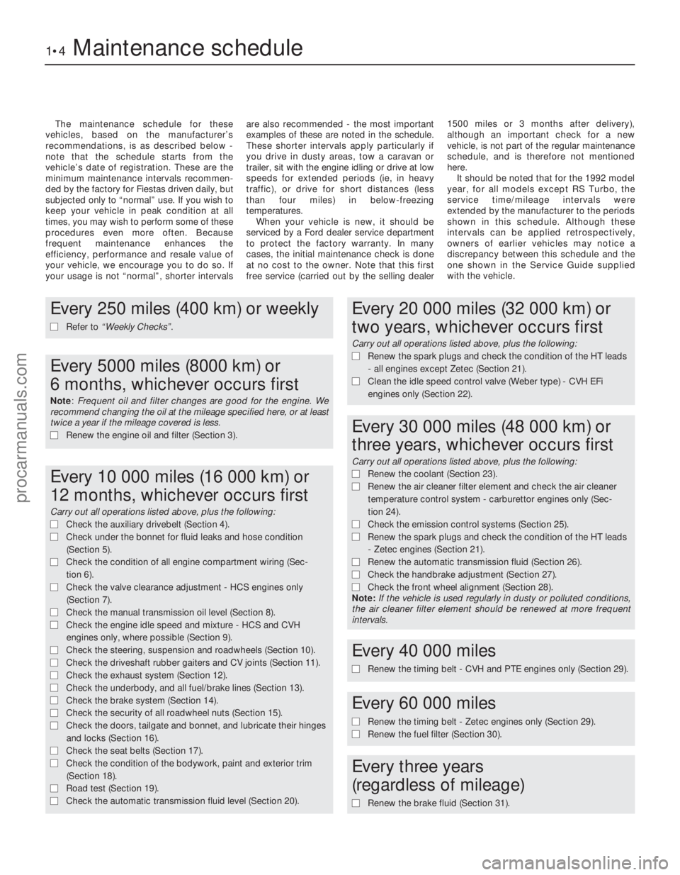
The maintenance schedule for these
vehicles, based on the manufacturer’s
recommendations, is as described below -
note that the schedule starts from the
vehicle’s date of registration. These are the
minimum maintenance intervals recommen-
ded by the factory for Fiestas driven daily, but
subjected only to “normal” use. If you wish to
keep your vehicle in peak condition at all
times, you may wish to perform some of these
procedures even more often. Because
frequent maintenance enhances the
efficiency, performance and resale value of
your vehicle, we encourage you to do so. If
your usage is not “normal”, shorter intervals are also recommended - the most important
examples of these are noted in the schedule.
These shorter intervals apply particularly if
you drive in dusty areas, tow a caravan or
trailer, sit with the engine idling or drive at low
speeds for extended periods (ie, in heavy
traffic), or drive for short distances (less
than four miles) in below-freezing
temperatures.
When your vehicle is new, it should be
serviced by a Ford dealer service department
to protect the factory warranty. In many
cases, the initial maintenance check is done
at no cost to the owner. Note that this first
free service (carried out by the selling dealer 1500 miles or 3 months after delivery),
although an important check for a new
vehicle, is not part of the regular maintenance
schedule, and is therefore not mentioned
here.
It should be noted that for the 1992 model
year, for all models except RS Turbo, the
service time/mileage intervals were
extended by the manufacturer to the periods
shown in this schedule. Although these
intervals can be applied retrospectively,
owners of earlier vehicles may notice a
discrepancy between this schedule and the
one shown in the Service Guide supplied
with the vehicle.
1•4Maintenance schedule
1595Ford Fiesta Remake
Every 250 miles (400 km) or weekly
m
m Refer to “Weekly Checks” .
Every 5000 miles (8000 km) or
6 months, whichever occurs first
Note: Frequent oil and filter changes are good for the engine. We
recommend changing the oil at the mileage specified here, or at least
twice a year if the mileage covered is less.
m m Renew the engine oil and filter (Section 3).
Every 10 000 miles (16 000 km) or
12 months, whichever occurs first
Carry out all operations listed above, plus the following:
m mCheck the auxiliary drivebelt (Section 4).
m
m Check under the bonnet for fluid leaks and hose condition
(Section 5).
m
m Check the condition of all engine compartment wiring (Sec-
tion 6).
m
m Check the valve clearance adjustment - HCS engines only
(Section 7).
m
m Check the manual transmission oil level (Section 8).
m
m Check the engine idle speed and mixture - HCS and CVH
engines only, where possible (Section 9).
m
m Check the steering, suspension and roadwheels (Section 10).
m
m Check the driveshaft rubber gaiters and CV joints (Section 11).
m
m Check the exhaust system (Section 12).
m
m Check the underbody, and all fuel/brake lines (Section 13).
m
m Check the brake system (Section 14).
m
m Check the security of all roadwheel nuts (Section 15).
m
m Check the doors, tailgate and bonnet, and lubricate their hinges
and locks (Section 16).
m
m Check the seat belts (Section 17).
m
m Check the condition of the bodywork, paint and exterior trim
(Section 18).
m
m Road test (Section 19).
m
m Check the automatic transmission fluid level (Section 20).
Every 20 000 miles (32 000 km) or
two years, whichever occurs first
Carry out all operations listed above, plus the following:
m mRenew the spark plugs and check the condition of the HT leads
- all engines except Zetec (Section 21).
m
m Clean the idle speed control valve (Weber type) - CVH EFi
engines only (Section 22).
Every 30 000 miles (48 000 km) or
three years, whichever occurs first
Carry out all operations listed above, plus the following:
m m Renew the coolant (Section 23).
m
m Renew the air cleaner filter element and check the air cleaner
temperature control system - carburettor engines only (Sec-
tion 24).
m m Check the emission control systems (Section 25).
m
m Renew the spark plugs and check the condition of the HT leads
- Zetec engines (Section 21).
m
m Renew the automatic transmission fluid (Section 26).
m
m Check the handbrake adjustment (Section 27).
m
m Check the front wheel alignment (Section 28).
Note: If the vehicle is used regularly in dusty or polluted conditions,
the air cleaner filter element should be renewed at more frequent
intervals.
Every 40 000 miles
m
m Renew the timing belt - CVH and PTE engines only (Section 29).
Every 60 000 miles
m
mRenew the timing belt - Zetec engines only (Section 29).
m
m Renew the fuel filter (Section 30).
Every three years
(regardless of mileage)
m m Renew the brake fluid (Section 31).
procarmanuals.com
http://vnx.su
Page 19 of 296
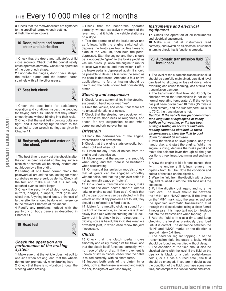
3Check that the roadwheel nuts are tightened
to the specified torque wrench setting.
4 Refit the wheel covers.
16 Door, tailgate and bonnet
check and lubrication
1
1Check that the doors and tailgate/boot lid
close securely. Check that the bonnet safety
catch operates correctly. Check the operation
of the door check straps.
2 Lubricate the hinges, door check straps,
the striker plates and the bonnet catch
sparingly with a little oil or grease.
17 Seat belt check
1
1 Check the seat belts for satisfactory
operation and condition. Inspect the webbing
for fraying and cuts. Check that they retract
smoothly and without binding into their reels.
2 Check that the seat belt mounting bolts are
tight, and if necessary tighten them to the
specified torque wrench settings as given in
Chapter 11.
18 Bodywork, paint and exterior trim check
1
1The best time to carry out this check is after
the car has been washed so that any surface
blemish or scratch will be clearly evident and
not hidden by a film of dirt.
2 Starting at one front corner check the
paintwork all around the car, looking for minor
scratches or more serious dents. Check all
the trim and make sure that it is securely
attached over its entire length.
3 Check the security of all door locks, door
mirrors, badges, bumpers, front grille and
wheel trim. Anything found loose, or in need of
further attention should be done with reference
to the relevant Chapters of this manual.
4 Rectify any problems noticed with the
paintwork or body panels as described in
Chapter 11.
19 Road test
1
Check the operation and
performance of the braking
system
1 Make sure that the vehicle does not pull to
one side when braking, and that the wheels
do not lock prematurely when braking hard.
2 Check that there is no vibration through the
steering when braking. 3
Check that the handbrake operates
correctly, without excessive movement of the
lever, and that it holds the vehicle stationary
on a slope.
4 Test the operation of the brake servo unit
as follows. With the engine switched off,
depress the footbrake four or five times to
exhaust the vacuum, then hold the pedal
depressed. Start the engine, and there should
be a noticeable “give” in the brake pedal as
vacuum builds up. Allow the engine to run for
at least two minutes, and then switch it off. If
the brake pedal is depressed again, it should
be possible to detect a hiss from the servo as
the pedal is depressed. After about four or five
applications, no further hissing should be
heard, and the pedal should feel considerably
firmer.
Steering and suspension
5 Check for any abnormalities in the steering,
suspension, handling or road “feel”.
6 Drive the vehicle, and check that there are
no unusual vibrations or noises.
7 Check that the steering feels positive, with
no excessive sloppiness or roughness, and
check for any suspension noises when
cornering and driving over bumps.
Drivetrain
8 Check the performance of the engine,
transmission and driveshafts.
9 Check that the engine starts correctly, both
when cold and when hot.
10 Listen for any unusual noises from the
engine and transmission.
11 Make sure that the engine runs smoothly
when idling, and that there is no hesitation
when accelerating.
12 On manual transmission models, check
that all gears can be engaged smoothly
without noise, and that the gear lever action is
not abnormally vague or “notchy”.
13 On automatic transmission models, make
sure that the drive seems smooth without
jerks or engine speed “flare-ups”. Check that
all the gear positions can be selected with the
vehicle at rest. If any problems are found, they
should be referred to a Ford dealer.
14 Listen for a metallic clicking sound from
the front of the vehicle, as the vehicle is driven
slowly in a circle with the steering on full-lock.
Carry out this check in both directions. If a
clicking noise is heard, this indicates wear in a
driveshaft joint, in which case renew the joint
if necessary.
Clutch
15 Check that the clutch pedal moves
smoothly and easily through its full travel, and
that the clutch itself functions correctly, with
no trace of slip or drag. If the movement is
uneven or stiff in places, check that the cable
is routed correctly, with no sharp turns.
16 Inspect both ends of the clutch inner
cable, both at the transmission end and inside
the car, for signs of wear and fraying.
Instruments and electrical
equipment
17 Check the operation of all instruments
and electrical equipment.
18 Make sure that all instruments read
correctly, and switch on all electrical equipment
in turn, to check that it functions properly.
20 Automatic transmission fluid level check
1
1The level of the automatic transmission fluid
should be carefully maintained. Low fluid level
can lead to slipping or loss of drive, while
overfilling can cause foaming, loss of fluid and
transmission damage.
2 The transmission fluid level should only be
checked when the transmission is hot (at its
normal operating temperature). If the vehicle
has just been driven over 10 miles (15 miles in
a cold climate), and the fluid temperature is 60
to 70ºC, the transmission is hot.
Caution: If the vehicle has just been driven
for a long time at high speed or in city
traffic in hot weather, or if it has been
pulling a trailer, an accurate fluid level
reading cannot be obtained. In these
circumstances, allow the fluid to cool
down for about 30 minutes.
3 Park the vehicle on level ground, apply the
handbrake, and start the engine. While the
engine is idling, depress the brake pedal and
move the selector lever through all the gear
positions three times, beginning and ending in
“P”.
4 Allow the engine to idle for one minute, then
(with the engine still idling) remove the
dipstick from its tube. Note the condition and
colour of the fluid on the dipstick.
5 Wipe the fluid from the dipstick with a clean
rag, and re-insert it into the filler tube until the
cap seats.
6 Pull the dipstick out again, and note the
fluid level. The level should be between
the “MIN” and “MAX” marks. If the level is
on the “MIN” mark, stop the engine, and add
the specified automatic transmission fluid
through the dipstick tube, using a clean funnel
if necessary. It is important not to introduce
dirt into the transmission when topping-up.
7 Add the fluid a little at a time, and keep
checking the level as previously described
until it is correct. The difference between the
“MIN” and “MAX” marks on the dipstick is
approximately 0.4 litres.
8 The need for regular topping-up of the
transmission fluid indicates a leak, which
should be found and rectified without delay.
9 The condition of the fluid should also be
checked along with the level. If the fluid on the
dipstick is black or a dark reddish-brown
colour, or if it has a burned smell, the fluid
should be changed. If you are in doubt about
the condition of the fluid, purchase some new
fluid, and compare the two for colour and smell.
1•18Every 10 000 miles or 12 months
1595Ford Fiesta Remakeprocarmanuals.com
http://vnx.su
Page 212 of 296
11
1595Ford Fiesta Remake
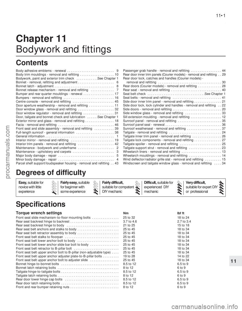
Torque wrench settingsNmlbf ft
Front seat slide mechanism-to-floor mounting bolts . . . . . . . . . . . . . . . 25 to 32 18 to 24
Rear seat backrest hinge to backrest . . . . . . . . . . . . . . . . . . . . . . . . . . . 3.7 to 4.6 2.7 to 3.4
Rear seat backrest hinge to body . . . . . . . . . . . . . . . . . . . . . . . . . . . . . 21 to 25 15 to 18
Rear seat belt anchors and stalks to body . . . . . . . . . . . . . . . . . . . . . . . 25 to 45 18 to 34
Rear seat belt retractor assembly to body . . . . . . . . . . . . . . . . . . . . . . . 25 to 45 18 to 34
Front seat belt stalks to floorpan . . . . . . . . . . . . . . . . . . . . . . . . . . . . . . 25 to 45 18 to 34
Front seat belt lower anchor bolt to body . . . . . . . . . . . . . . . . . . . . . . . 25 to 45 18 to 34
Front seat belt lower anchor slide bar bolt to body . . . . . . . . . . . . . . . . 25 to 45 18 to 34
Front seat belt retractor to B-pillar bolt . . . . . . . . . . . . . . . . . . . . . . . . . 25 to 45 18 to 34
Front seat belt upper anchor bolt to B-pillar (non-adjustable type) . . . . 25 to 45 18 to 34
Front seat belt upper anchor adjuster plate-to-B-pillar bolts . . . . . . . . . 19 to 28 14 to 22
Front seat belt upper anchor bolt to adjuster slide . . . . . . . . . . . . . . . . 25 to 45 18 to 34
Bonnet hinge-to-bonnet bolts . . . . . . . . . . . . . . . . . . . . . . . . . . . . . . . . 8.5 to 12 6.5 to 9
Bonnet latch retaining bolts . . . . . . . . . . . . . . . . . . . . . . . . . . . . . . . . . . 8 to 12 6 to 9
Tailgate hinge-to-tailgate bolts . . . . . . . . . . . . . . . . . . . . . . . . . . . . . . . . 8.5 to 12 6.5 to 9
Tailgate latch retaining bolts . . . . . . . . . . . . . . . . . . . . . . . . . . . . . . . . . . 8 to 12 6 to 9
Rear door lower hinge cap bolts . . . . . . . . . . . . . . . . . . . . . . . . . . . . . . 8.5 to 12 6.5 to 9
Rear door latch retaining bolts . . . . . . . . . . . . . . . . . . . . . . . . . . . . . . . . 8.5 to 12 6.5 to 9
Front and rear bumper retaining nuts . . . . . . . . . . . . . . . . . . . . . . . . . . . 8 to 12 6 to 9
Chapter 11
Bodywork and fittings
Body adhesive emblems - renewal . . . . . . . . . . . . . . . . . . . . . . . . . . 9
Body trim mouldings - removal and refitting . . . . . . . . . . . . . . . . . . . 10
Bodywork, paint and exterior trim check . . . . . . . . . . . .See Chapter 1
Bonnet - removal, refitting and adjustment . . . . . . . . . . . . . . . . . . . . 6
Bonnet latch - adjustment . . . . . . . . . . . . . . . . . . . . . . . . . . . . . . . . . 8
Bonnet release mechanism - removal and refitting . . . . . . . . . . . . . 7
Bumper and rear quarter mouldings - renewal . . . . . . . . . . . . . . . . . 17
Bumpers - removal and refitting . . . . . . . . . . . . . . . . . . . . . . . . . . . . 16
Centre console - removal and refitting . . . . . . . . . . . . . . . . . . . . . . . 45
Door aperture weatherstrip - removal and refitting . . . . . . . . . . . . . . 11
Door window glass - removal and refitting . . . . . . . . . . . . . . . . . . . . 32
Door window regulator - removal and refitting . . . . . . . . . . . . . . . . . 31
Door, tailgate and bonnet check and lubrication . . . . . .See Chapter 1
Exterior mirror and glass - removal and refitting . . . . . . . . . . . . . . . . 18
Facia - removal and refitting . . . . . . . . . . . . . . . . . . . . . . . . . . . . . . . 46
Front seat and slide assembly - removal and refitting . . . . . . . . . . . 39
Full-length sunroof - general information . . . . . . . . . . . . . . . . . . . . . 38
General information . . . . . . . . . . . . . . . . . . . . . . . . . . . . . . . . . . . .\
. . 1
Interior mirror - removal and refitting . . . . . . . . . . . . . . . . . . . . . . . . 19
Interior trim panels - removal and refitting . . . . . . . . . . . . . . . . . . . . 42
Maintenance - bodywork and underframe . . . . . . . . . . . . . . . . . . . . 2
Maintenance - upholstery and carpets . . . . . . . . . . . . . . . . . . . . . . . 3
Major body damage - repair . . . . . . . . . . . . . . . . . . . . . . . . . . . . . . . 5
Minor body damage - repair . . . . . . . . . . . . . . . . . . . . . . . . . . . . . . . 4
Parcel shelf support/loudspeaker housing - removal and refitting . . 43 Passenger grab handle - removal and refitting . . . . . . . . . . . . . . . . . 44
Rear door inner trim panels (Courier models) - removal and refitting . . 29
Rear door lock, catches and handles (Courier models) -
removal and refitting . . . . . . . . . . . . . . . . . . . . . . . . . . . . . . . . . . . 30
Rear doors (Courier models) - removal and refitting . . . . . . . . . . . . . 28
Rear seat - removal and refitting . . . . . . . . . . . . . . . . . . . . . . . . . . . . 40
Seat belt check . . . . . . . . . . . . . . . . . . . . . . . . . . . . . . . .See Chap\
ter 1
Seat belts - removal and refitting . . . . . . . . . . . . . . . . . . . . . . . . . . . 41
Side door inner trim panel - removal and refitting . . . . . . . . . . .\
. . . . 21
Side door lock, lock cylinder and handles - removal and refitting . . 22
Side doors - removal and refitting . . . . . . . . . . . . . . . . . . . . . . . . . . . 20
Side window glass - removal and refitting . . . . . . . . . . . . . . . . . . . . 33
Sill extension moulding - removal and refitting . . . . . . . . . . . . . . . . . 12
Sunroof panel - removal and refitting . . . . . . . . . . . . . . . . . . . . . . . . 35
Sunroof panel seal - renewal . . . . . . . . . . . . . . . . . . . . . . . . . . . . . . . 36
Sunroof weatherseal - removal and refitting . . . . . . . . . . . . . . . . . . . 37
Tailgate - removal and refitting . . . . . . . . . . . . . . . . . . . . . . . . . . . . . 24
Tailgate inner trim panel - removal and refitting . . . . . . . . . . . . . . . . 26
Tailgate lock components - removal and refitting . . . . . . . . . . . . . . . 27
Tailgate spoiler - removal and refitting . . . . . . . . . . . . . . . . . . . . . . . 25
Tailgate support strut - removal and refitting . . . . . . . . . . . . . . . . . . 23
Wheelarch liners - removal and refitting . . . . . . . . . . . . . . . . . . . . . . 13
Wheelarch mouldings - removal and refitting . . . . . . . . . . . . . . . . . . 14
Wind deflector/radiator grille slat - removal and refitting . . . . . . . . . 15
Windscreen and tailgate window glass - removal and refitting . . . . 34
11•1
Specifications Contents
Easy, suitable for
novice with little
experience Fairly easy,
suitable
for beginner with
some experience Fairly difficult,
suitable for competent
DIY mechanic
Difficult,
suitable for
experienced DIY
mechanic Very difficult,
suitable for expert DIY
or professional
Degrees of difficulty
54321
procarmanuals.com
http://vnx.su
Page 213 of 296
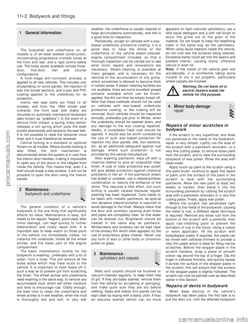
1 General information
The bodyshell and underframe on all
models is of all-steel welded construction,
incorporating progressive crumple zones at
the front and rear, and a rigid centre safety
cell. The body styles available include three-
door, five-door, Van and Courier
configurations. A multi-stage anti-corrosion process is
applied to all new vehicles. This includes zinc
phosphating on some panels, the injection of
wax into boxed sections, and a wax and PVC
coating applied to the underbody for its
protection. Inertia reel seat belts are fitted to all
models, and from the 1994 model year
onwards, the front seat belt stalks are
mounted on automatic mechanical tensioners
(also known as “grabbers”). In the event of a
serious front impact, a spring mass sensor
releases a coil spring which pulls the stalk
buckle downwards and tensions the seat belt.
It is not possible to reset the tensioner once
fired, and it must therefore be renewed. Central locking is a standard or optional
fitment on all models. Where double-locking is
also fitted, the lock mechanism is
disconnected (when the system is in use) from
the interior door handles, making it impossible
to open any of the doors or the tailgate from
inside the vehicle. This means that, even if a
thief should break a side window, it will not be
possible to open the door using the interior
handle.
2 Maintenance -
bodywork and underframe
1
The general condition of a vehicle’s
bodywork is the one thing that significantly
affects its value. Maintenance is easy, but
needs to be regular. Neglect, particularly after
minor damage, can lead quickly to further
deterioration and costly repair bills. It is
important also to keep watch on those parts
of the vehicle not immediately visible, for
instance the underside, inside all the wheel
arches, and the lower part of the engine
compartment. The basic maintenance routine for the
bodywork is washing - preferably with a lot of
water, from a hose. This will remove all the
loose solids which may have stuck to the
vehicle. It is important to flush these off in
such a way as to prevent grit from scratching
the finish. The wheel arches and underframe
need washing in the same way, to remove any
accumulated mud, which will retain moisture
and tend to encourage rust. Oddly enough,
the best time to clean the underframe and
wheel arches is in wet weather, when the mud
is thoroughly wet and soft. In very wet weather, the underframe is usually cleaned of
large accumulations automatically, and this is
a good time for inspection.
Periodically, except on vehicles with a wax-
based underbody protective coating, it is a
good idea to have the whole of the
underframe of the vehicle steam-cleaned,
engine compartment included, so that a
thorough inspection can be carried out to see
what minor repairs and renovations are
necessary. Steam-cleaning is available at
many garages, and is necessary for the
removal of the accumulation of oily grime,
which sometimes is allowed to become thick
in certain areas. If steam-cleaning facilities are
not available, there are some excellent grease
solvents available which can be brush-
applied; the dirt can then be simply hosed off.
Note that these methods should not be used
on vehicles with wax-based underbody
protective coating, or the coating will be
removed. Such vehicles should be inspected
annually, preferably just prior to Winter, when
the underbody should be washed down, and
any damage to the wax coating repaired.
Ideally, a completely fresh coat should be
applied. It would also be worth considering
the use of such wax-based protection for
injection into door panels, sills, box sections,
etc, as an additional safeguard against rust
damage, where such protection is not
provided by the vehicle manufacturer. After washing paintwork, wipe off with a
chamois leather to give an unspotted clear
finish. A coat of clear protective wax polish
will give added protection against chemical
pollutants in the air. If the paintwork sheen
has dulled or oxidised, use a cleaner/polisher
combination to restore the brilliance of the
shine. This requires a little effort, but such
dulling is usually caused because regular
washing has been neglected. Care needs to
be taken with metallic paintwork, as special
non-abrasive cleaner/polisher is required to
avoid damage to the finish. Always check that
the door and ventilator opening drain holes
and pipes are completely clear, so that water
can be drained out .Brightwork should be
treated in the same way as paintwork.
Windscreens and windows can be kept clear
of the smeary film which often appears, by the
use of proprietary glass cleaner. Never use
any form of wax or other body or chromium
polish on glass.
3 Maintenance -
upholstery and carpets
1
Mats and carpets should be brushed or
vacuum-cleaned regularly, to keep them free
of grit. If they are badly stained, remove them
from the vehicle for scrubbing or sponging,
and make quite sure they are dry before
refitting. Seats and interior trim panels can be
kept clean by wiping with a damp cloth. If they
do become stained (which can be more apparent on light-coloured upholstery), use a
little liquid detergent and a soft nail brush to
scour the grime out of the grain of the
material. Do not forget to keep the headlining
clean in the same way as the upholstery.
When using liquid cleaners inside the vehicle,
do not over-wet the surfaces being cleaned.
Excessive damp could get into the seams and
padded interior, causing stains, offensive
odours or even rot.
Note
:
If the inside of the vehicle gets wet
accidentally, it is worthwhile taking some
trouble to dry it out properly, particularly
where carpets are involved .
Warning: Do not leave oil or
electric heaters inside the
vehicle for this purpose.
4 Minor body damage-
repair
3
Repairs of minor scratches in
bodywork
If the scratch is very superficial, and does
not penetrate to the metal of the bodywork,
repair is very simple. Lightly rub the area of
the scratch with a paintwork renovator, or a
very fine cutting paste, to remove loose paint
from the scratch, and to clear the surrounding
bodywork of wax polish. Rinse the area with
clean water. Apply touch-up paint to the scratch using a
fine paint brush; continue to apply fine layers
of paint until the surface of the paint in the
scratch is level with the surrounding
paintwork. Allow the new paint at least two
weeks to harden, then blend it into the
surrounding paintwork by rubbing the scratch
area with a paintwork renovator or a very fine
cutting paste. Finally, apply wax polish. Where the scratch has penetrated right
through to the metal of the bodywork, causing
the metal to rust, a different repair technique
is required. Remove any loose rust from the
bottom of the scratch with a penknife, then
apply rust-inhibiting paint to prevent the
formation of rust in the future. Using a rubber
or nylon applicator, fill the scratch with
bodystopper paste. If required, this paste can
be mixed with cellulose thinners to provide a
very thin paste which is ideal for filling narrow
scratches. Before the stopper-paste in the
scratch hardens, wrap a piece of smooth
cotton rag around the top of a finger. Dip the
finger in cellulose thinners, and quickly sweep
it across the surface of the stopper-paste in
the scratch; this will ensure that the surface
of the stopper-paste is slightly hollowed. The
scratch can now be painted over as described
earlier in this Section.
Repairs of dents in bodywork
When deep denting of the vehicle’s
bodywork has taken place, the first task is to
pull the dent out, until the affected bodywork
11•2 Bodywork and fittings
1595Ford Fiesta Remakeprocarmanuals.com
http://vnx.su
Page 214 of 296

almost attains its original shape. There is little
point in trying to restore the original shape
completely, as the metal in the damaged area
will have stretched on impact, and cannot be
reshaped fully to its original contour. It is
better to bring the level of the dent up to a
point which is about 3 mm below the level of
the surrounding bodywork. In cases where the
dent is very shallow anyway, it is not worth
trying to pull it out at all. If the underside of the
dent is accessible, it can be hammered out
gently from behind, using a mallet with a
wooden or plastic head. Whilst doing this,
hold a suitable block of wood firmly against
the outside of the panel, to absorb the impact
from the hammer blows and thus prevent a
large area of the bodywork from being
“belled-out”.Should the dent be in a section of the
bodywork which has a double skin, or some
other factor making it inaccessible from
behind, a different technique is called for. Drill
several small holes through the metal inside
the area - particularly in the deeper section.
Then screw long self-tapping screws into the
holes, just sufficiently for them to gain a good
purchase in the metal. Now the dent can be
pulled out by pulling on the protruding heads
of the screws with a pair of pliers. The next stage of the repair is the removal
of the paint from the damaged area, and from
an inch or so of the surrounding “sound”
bodywork. This is accomplished most easily
by using a wire brush or abrasive pad on a
power drill, although it can be done just as
effectively by hand, using sheets of abrasive
paper. To complete the preparation for filling,
score the surface of the bare metal with a
screwdriver or the tang of a file, or
alternatively, drill small holes in the affected
area. This will provide a really good “key” for
the filler paste.
To complete the repair, see the Section on
filling and respraying.
Repairs of rust holes or gashes
in bodywork
Remove all paint from the affected area,
and from an inch or so of the surrounding
“sound” bodywork, using an abrasive pad or a
wire brush on a power drill. If these are not
available, a few sheets of abrasive paper will
do the job most effectively. With the paint
removed, you will be able to judge the severity
of the corrosion, and therefore decide
whether to renew the whole panel (if this is
possible) or to repair the affected area. New
body panels are not as expensive as most
people think, and it is often quicker and more
satisfactory to fit a new panel than to attempt
to repair large areas of corrosion. Remove all fittings from the affected area,
except those which will act as a guide to the
original shape of the damaged bodywork (eg
headlight shells etc). Then, using tin snips or a
hacksaw blade, remove all loose metal and
any other metal badly affected by corrosion.
Hammer the edges of the hole inwards, in order to create a slight depression for the filler
paste.
Wire-brush the affected area to remove the
powdery rust from the surface of the
remaining metal. Paint the affected area with
rust-inhibiting paint, if the back of the rusted
area is accessible, treat this also. Before filling can take place, it will be
necessary to block the hole in some way. This
can be achieved by the use of aluminium or
plastic mesh, or aluminium tape. Aluminium or plastic mesh, or glass-fibre
matting, is probably the best material to use
for a large hole. Cut a piece to the
approximate size and shape of the hole to be
filled, then position it in the hole so that its
edges are below the level of the surrounding
bodywork. It can be retained in position by
several blobs of filler paste around its
periphery. Aluminium tape should be used for small or
very narrow holes. Pull a piece off the roll, trim
it to the approximate size and shape required,
then pull off the backing paper (if used) and
stick the tape over the hole; it can be
overlapped if the thickness of one piece is
insufficient. Burnish down the edges of the
tape with the handle of a screwdriver or
similar, to ensure that the tape is securely
attached to the metal underneath.
Bodywork repairs - filling and
respraying
Before using this Section, see the Sections
on dent, deep scratch, rust holes and gash
repairs. Many types of bodyfiller are available, but
generally speaking, those proprietary kits
which contain a tin of filler paste and a tube of
resin hardener are best for this type of repair.
A wide, flexible plastic or nylon applicator will
be found invaluable for imparting a smooth
and well-contoured finish to the surface of the
filler. Mix up a little filler on a clean piece of card
or board - measure the hardener carefully
(follow the maker’s instructions on the pack),
otherwise the filler will set too rapidly or too
slowly. Using the applicator, apply the filler
paste to the prepared area; draw the
applicator across the surface of the filler to
achieve the correct contour and to level the
surface. As soon as a contour that
approximates to the correct one is achieved,
stop working the paste - if you carry on too
long, the paste will become sticky and begin
to “pick-up” on the applicator. Continue to
add thin layers of filler paste at 20-minute
intervals, until the level of the filler is just
proud of the surrounding bodywork. Once the filler has hardened, the excess
can be removed using a metal plane or file.
From then on, progressively-finer grades of
abrasive paper should be used, starting with a
40-grade production paper, and finishing with
a 400-grade wet-and-dry paper. Always wrap
the abrasive paper around a flat rubber, cork,
or wooden block - otherwise the surface of the filler will not be completely flat. During the
smoothing of the filler surface, the wet-and-
dry paper should be periodically rinsed in
water. This will ensure that a very smooth
finish is imparted to the filler at the final stage.
At this stage, the “dent” should be
surrounded by a ring of bare metal, which in
turn should be encircled by the finely
“feathered” edge of the good paintwork.
Rinse the repair area with clean water, until all
of the dust produced by the rubbing-down
operation has gone. Spray the whole area with a light coat of
primer - this will show up any imperfections in
the surface of the filler. Repair these
imperfections with fresh filler paste or
bodystopper, and once more smooth the
surface with abrasive paper. Repeat this
spray-and-repair procedure until you are
satisfied that the surface of the filler, and the
feathered edge of the paintwork, are perfect.
Clean the repair area with clean water, and
allow to dry fully.
The repair area is now ready for final
spraying. Paint spraying must be carried out
in a warm, dry, windless and dust-free
atmosphere. This condition can be created
artificially if you have access to a large indoor
working area, but if you are forced to work in
the open, you will have to pick your day very
carefully. If you are working indoors, dousing
the floor in the work area with water will help
to settle the dust which would otherwise be in
the atmosphere. If the repair area is confined
to one body panel, mask off the surrounding
panels; this will help to minimise the effects of
a slight mis-match in paint colours. Bodywork
fittings (eg chrome strips, door handles etc)
will also need to be masked off. Use genuine
masking tape, and several thicknesses of
newspaper, for the masking operations. Before commencing to spray, agitate the
aerosol can thoroughly, then spray a test area
(an old tin, or similar) until the technique is
mastered. Cover the repair area with a thick
coat of primer; the thickness should be built
up using several thin layers of paint, rather
than one thick one. Using 400-grade wet-and-
dry paper, rub down the surface of the primer
until it is really smooth. While doing this, the
work area should be thoroughly doused with
water, and the wet-and-dry paper periodically
rinsed in water. Allow to dry before spraying
on more paint. Spray on the top coat, again building up the
thickness by using several thin layers of paint.
Start spraying at one edge of the repair area,
and then, using a side-to-side motion, work
until the whole repair area and about 2 inches
of the surrounding original paintwork is
covered. Remove all masking material 10 to
Bodywork and fittings 11•3
11
1595Ford Fiesta Remake
If bodystopper is used, it can be mixed with cellulose
thinners to form a really thin
paste which is ideal for
filling small holes.
procarmanuals.com
http://vnx.su
Page 216 of 296
4Pull the latch end of the cable into the
engine compartment, noting cable routing and
clips fitted. Remove the cable from its clips.
5 Detach the cable from its release lever on
the steering column, by aligning the cable
core with the slot on the release lever and
withdrawing the end fixing. Detach the cable
from its outer core abutment on the steering
column lock housing.
6 Unclip the cable from its pedal box
location, then detach the bulkhead grommet
and pass the cable through into the engine
compartment. Withdraw the cable from the
vehicle.
7 The release lever on the steering column
may be removed, if required, by unhooking
the spring from its retaining arms, then
disengaging its retaining arms from the
steering column lock housing.
Refitting
8 Refit the release lever, if removed, by
reversing the method of removal.
9 To install the release cable, first pass the
latch end of the cable down the right-hand
side of the steering column, through its
bulkhead location, and out into the engine
compartment.
10 Fit the cable to its clip on the pedal box
assembly, then reconnect the cable to the
release lever and the steering column lock
housing abutment by reversing the method of
removal.
11 Where applicable, refit the choke warning
light switch/pull control assembly, to the lower steering column shroud, by reversing the
method of removal. Refit the shroud.
12
Seat the release cable grommet into the
bulkhead.
13 Route and secure the release cable in the
engine compartment.
14 Reconnect the release cable to the latch,
then refit the latch to the body, setting the
latch at its maximum height position, and
tightening only the bottom retaining screw.
15 Adjust the latch for flush bonnet closure in
accordance with Section 8.
8 Bonnet latch - adjustment
1
1To adjust the bonnet latch, remove the two
upper latch retaining screws, then with the
latch raised to its maximum height position
and secured with the lower retaining screw,
close the bonnet.
2 Slacken the lower latch retaining screw,
through the gap between the leading edge of
the bonnet and the radiator grille slot, then
set the bonnet so it sits flush with its
surrounding panels - it may be necessary to
adjust the height of the bump stops (see
Section 6) if they have been moved in any
way, or if fitting a new bonnet.
3 With the desired bonnet closure obtained,
fully tighten the lower latch retaining screw,
then open the bonnet and refit the two upper
latch retaining screws, tightening to the
specified torque.
9 Body adhesive emblems -
renewal
1
1 Using a length of strong thin diameter cord
(fishing line is ideal), break the adhesive bond
between the emblem and the panel.
2 Thoroughly clean all traces of the old
adhesive from the emblem location, using
methylated spirit, taking all normal safety
precautions. Allow the emblem location to
dry.
3 Gently heat the new emblem until it is warm
to the touch. 4
Peel the protective backing paper from the
emblem then, taking care not to touch the
adhesive, position the emblem on the panel.
Maintain hand pressure evenly for at least
thirty seconds to ensure a good bond.
10 Body trim mouldings -
removal and refitting
1
Roof drip rail moulding (all
models except Courier)
Removal
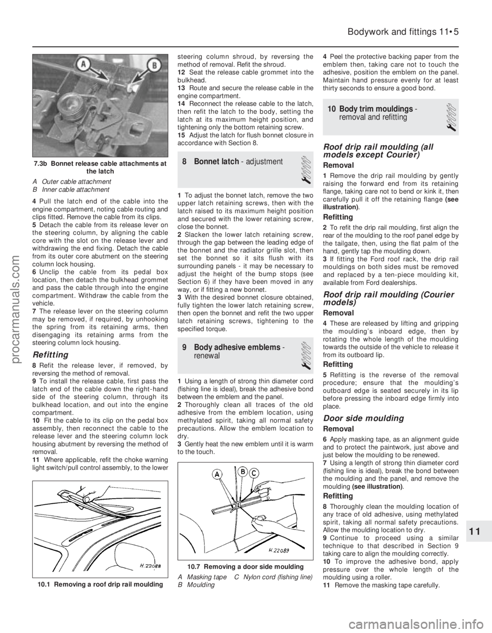
1 Remove the drip rail moulding by gently
raising the forward end from its retaining
flange, taking care not to bend or kink it, then
carefully pull it off the retaining flange (see
illustration) .
Refitting
2To refit the drip rail moulding, first align the
rear of the moulding to the roof panel edge by
the tailgate, then, using the flat palm of the
hand, gently tap the moulding down.
3 If fitting the Ford roof rack, the drip rail
mouldings on both sides must be removed
and replaced by a ten-piece moulding kit,
available from Ford dealerships.
Roof drip rail moulding (Courier
models)
Removal
4 These are released by lifting and gripping
the moulding’s inboard edge, then by
rotating the whole length of the moulding
towards the outside of the vehicle to release it
from its outboard lip.
Refitting
5 Refitting is the reverse of the removal
procedure; ensure that the moulding’s
outboard edge is seated securely in its lip
before pressing the inboard edge firmly into
place.
Door side moulding
Removal
6 Apply masking tape, as an alignment guide
and to protect the paintwork, just above and
just below the moulding to be renewed.
7 Using a length of strong thin diameter cord
(fishing line is ideal), break the bond between
the moulding and the panel, and remove the
moulding (see illustration) .
Refitting
8Thoroughly clean the moulding location of
any trace of old adhesive, using methylated
spirit, taking all normal safety precautions.
Allow the moulding location to dry.
9 Continue to proceed using a similar
technique to that described in Section 9
taking care to align the moulding correctly.
10 To improve the adhesive bond, apply
pressure over the whole length of the
moulding using a roller.
11 Remove the masking tape carefully.
Bodywork and fittings 11•5
7.3b Bonnet release cable attachments at
the latch
A Outer cable attachment
B Inner cable attachment
10.7 Removing a door side moulding
A Masking tape C Nylon cord (fishing line)
B Moulding
10.1 Removing a roof drip rail moulding
11
1595Ford Fiesta Remakeprocarmanuals.com
http://vnx.su
Page 222 of 296

Refitting
7To refit, first align the trim panel to the door,
secure its upper edge into its hook fastenings,
then press into position to engage the trim
clips. Where electric window switches are
fitted, reconnect the switch wiring multi-plugs
before fitting the panel.
8 If necessary, refit the clip to the window
regulator handle, then refit the handle to the
regulator shaft by pushing it on. The clip
should engage positively, in the annular
groove on the shaft.
9 Refit the door stowage pocket/speaker
grille moulding, armrest/doorpull and door
interior release handle bezel, as applicable, by
reversing the method of removal.
10 Refit the interior weatherstrip to its
location, tapping it down into position, being
careful not to bend or kink it. On front doors, it
will be necessary to slide its forward edge
under the door mirror trim before tapping into
position.
22 Side door lock, lock cylinder
and handles - removal and
refitting
2
Exterior handle
Removal
1 Remove the door inner trim panel, as
described in Section 21.
2 Locally detach the PVC sheet from the door
to allow access into the door cavity. Do not
tear the sheet; cut closely around the clips, as
required.
3 Disconnect the handle operating rod from
the latch assembly, by twisting the clip and
withdrawing the rod, as applicable.
4 Remove the two screws securing the
handle then, from the outside, withdraw
the handle and rod, guiding the rod out
through the door skin as necessary (see
illustrations) . The handle and rod may be
disconnected as required.
Refitting
5 Refitting is a reversal of the removal
procedure. On completion, re-secure the PVC
sheet then refit the inner trim panel as
described in Section 21.
Door lock barrel
Removal
6 Remove the door inner trim panel, as
described in Section 21.
7 Locally detach the PVC sheet from the door
to allow access into the door cavity. Do not
tear the sheet; cut closely around the clips, as
required.
8 Drill out the rivets securing the door glass
guide above the lock barrel, and remove it.
9 Disconnect the lock barrel operating rod
from the latch assembly, by twisting the clip
and withdrawing the rod.
10 Release the lock barrel retaining clip by
withdrawing it upwards, then from the
outside, withdraw the lock barrel and rod,
guiding the rod out through the door skin. The
lock barrel and rod may be disconnected as
required.
Refitting
11 Refitting is a reversal of the removal
procedure. Ensure that the lock barrel gasket
is located correctly between the lock barrel
outer surround and the door skin, and that the door glass guide is riveted securely. Check
that the window operates smoothly and
correctly, by temporarily refitting the regulator
handle or operating the electric window
motor.
12
On completion, re-secure the PVC sheet
then refit the inner trim panel as described in
Section 21.
Door latch and interior release
handle
Removal
13 Remove the door inner trim panel, as
described in Section 21.
14 Locally detach the PVC sheet from the
door to allow access into the door cavity. Do
not tear the sheet; cut closely around the
clips, as required.
15 On rear doors fitted with central locking,
undo the two screws securing the rod guard
and remove it (see illustration) .
16 Disconnect the operating rods from the
latch assembly as necessary. On rear doors
with central locking, disconnect and release
the motor loom multi-plug assembly, and
withdraw the motor side of the loom back into
the door cavity. Undo the three screws
securing the motor assembly, disengage its
operating rod and remove it from the vehicle
(see illustration) .
Bodywork and fittings 11•11
22.4b Removing the door exterior handle,
guiding its operating rod out through the door skin (front door)22.4a Door exterior handle and lock barrelsecuring arrangements (front door)
A Handle screw locations
B Lock barrel retaining clip21.5 Disengaging the hook fixings on the
base of the door stowage pocket/speaker grille moulding
22.16 Central locking motor retainingscrews (A), and loom multi-plug
assembly (B) on rear door22.15 Rod guard securing screws
(arrowed) on rear doors with central
locking only
11
1595Ford Fiesta Remakeprocarmanuals.com
http://vnx.su
Page 223 of 296

17On front doors, vehicles fitted with central
locking have a latch with an integral motor. If
central locking is fitted, prise up and twist the
rearward clips securing the motor loom to the
door, to free the loom, disconnect the multi-
plugs and withdraw the loom (motor side)
back into the door cavity.
18 Remove the interior release handle
surround, then prise up the forward end of the
handle unit. Release the handle from its
rearward location by sliding it forward to
disengage the hooks (see illustration).
19 Detach the door interior release cable
from its retaining clips on the door panel.
20 Remove the latch securing screws from
the upper rear edge of the door, and with-
draw the latch and interior release mechanism
from the vehicle (see illustration) .
21 Remove the cable cover from the latch
assembly, then detach the cable from the
latch.
22 Peel the sponge pad from the reverse side
of the interior release handle, and remove the
outer cable from its abutment in the body of
the handle. Remove the inner cable core by
aligning the core with the slot by its end fixing,
then slide the end fixing out.
Refitting
23 Refitting is a reversal of the removal
procedure. On completion, re-secure the PVC
sheet then refit the inner trim panel as
described in Section 21.
23 Tailgate support strut -
removal and refitting
1
Removal
1 Open the tailgate and support it securely,
using a length of timber, or have an assistant
hold it open.
2 Detach the support strut by raising the
retaining clip and pulling the strut away from
its ball stud fixing on the tailgate. Do not raise
the clip more than 4.0 mm, or the support
strut will be damaged.
3 Repeat the operation on the other end of
the support strut.
Refitting
4 To refit, align the thicker (cylinder) end of
the support strut to the ball stud fixing on the
tailgate, then push until it snaps into
engagement.
5 Repeat the operation with the thinner
(piston) end of the support strut to the ball
stud fixing on the body.
24 Tailgate -
removal and refitting
1
Removal
1 Open the tailgate and mark around the
hinge positions on the tailgate panel itself.
2 Remove the central blanking plug from the
upper portion of the tailgate to expose the
washer jet, and disconnect the washer hose
from the jet base, as applicable. Free the
washer hose grommet and withdraw the hose
from the tailgate.
3 Disconnect the support strut from the
tailgate, as described in Section 23.
4 With the aid of an assistant, undo the four
bolts securing the tailgate to the vehicle body
and remove the tailgate.
Refitting
5 To refit, align the hinges on the body with
the marks made on the tailgate panel, then
refit and tighten the four bolts to secure. Refit
the support strut as described in Section 23.
6 The remainder of the refitting operation is a
reversal of the removal procedure.
7 Close the tailgate and check the alignment.
Adjust as necessary to obtain an even gap
between the tailgate and all adjacent panels.
25 Tailgate spoiler -
removal and refitting
2
Removal
1 Drill out the rivets securing the outer edges
of the spoiler to the tailgate. 2
Open the tailgate and remove the four
blanking plugs covering the spoiler retaining
nuts. Undo the nuts and remove the spoiler.
Refitting
3 To refit, first align the spoiler mounting
studs to their tailgate fixing holes, then rivet
the outer edges of the spoiler to the tailgate.
4 Refit the four retaining nuts and tighten to
the specified torque.
5 Refit the blanking plugs.
26 Tailgate inner trim panel -
removal and refitting
1
Removal
1 Open the tailgate then, using a screwdriver,
remove the seven plastic retaining screws
from the trim panel.
2 Remove the square plastic clip from the
trim panel.
3 Disengage the clips from the panel edge
nearest the window, and manoeuvre the panel
to release the hooks on the other panel edge.
Withdraw the trim panel from the vehicle.
Refitting
4 Refitting is a reversal of removal.
27 Tailgate lock components -
removal and refitting
2
Note: For vehicles equipped with remote
tailgate release, removal and refitting
procedures for the tailgate remote release
motor are contained in Chapter 12.
Removal
1 Remove the tailgate inner trim panel as
described in Section 26.
2 Remove the two Torx screws securing the
tailgate latch, then pull it down, disconnect its
operating rod and remove the latch from the
vehicle (see illustration) .
3 Remove the bolt securing the lock barrel
11•12 Bodywork and fittings
27.2 Tailgate latch and its Torx securing
screws (arrowed)
22.20 Removing the latch securing screws (arrowed)22.18 Detaching the interior door release handle
1595Ford Fiesta Remakeprocarmanuals.com
http://vnx.su
Page 224 of 296

retainer to the tailgate, then withdraw the
retainer (see illustration) .
4 Remove the lock assembly from the tailgate
by partially withdrawing the lock, twisting it so
that the lock rod can be removed, then fully
withdrawing.
Refitting
5 To refit, first ensure that the lock gasket is
in position, then partially insert the lock into
the tailgate and reconnect the lock rod. Fully
insert the lock and refit its retainer and
securing bolt.
6 Using an electrician’s thin screwdriver,
prise up the lever on the latch and fit the lock
rod to it, ensuring that it fully engages.
7 Align the latch with its location and refit its
two securing screws.
8 Check for correct lock operation before
refitting the tailgate interior trim panel as
described in Section 26.
28 Rear doors (Courier models) - removal and refitting
1
Removal
1Open the door and disconnect the wiring
leading to it; all connectors are accessible
from the openings inside the door frame. 2
Unclip the door check arm, and unscrew
the bottom hinge’s cap securing bolt (see
illustration) .
3 Lift the door off its hinges and withdraw it.
Refitting
4Refitting is the reverse of the removal
procedure; apply grease to the hinge pins,
and tighten the cap bolt securely.
5 The door hinges can be unbolted from the
door and frame; either remove the door first,
or support it carefully and remove the hinge
with it in place.
29 Rear door inner trim panels (Courier models) -
removal and refitting
1
Removal
1 Remove the interior handle bezel by
pushing it away from the door’s hinges until it
can be withdrawn.
2 Using either a trim clip releasing tool or a
screwdriver with a broad flat blade, and
protecting the paintwork and trim with a layer
of rag, extract the clips securing the panel and
withdraw it.
Refitting
3 Refitting is the reverse of the removal
procedure.
30 Rear door lock, catches and
handles (Courier models) -
removal and refitting
1
Interior handle
Removal
1 Remove the inner trim panel, as described
in Section 29.
2 Remove its four retaining screws, and
withdraw the complete latch assembly (see
illustrations) .
3 Disconnect the link rod and remove the
single retaining screw to withdraw the interior
handle.
Refitting
4 Refitting is the reverse of the removal
procedure.
Exterior handle and lock
assembly
Removal
5 Remove the inner trim panel, as described
in Section 29.
6 Remove its four retaining screws, and
withdraw the complete latch assembly.
7 Using pliers, rotate the exterior handle
locking ring anti-clockwise to release it, then
withdraw the handle with the inner and outer
gaskets (see illustrations) .
8 The lock assembly is secured by a circlip to
the handle.
Bodywork and fittings 11•13
30.2a Courier rear door latch assembly retaining screws (arrowed)28.2 Unscrewing the bottom hinge’s capsecuring bolt on Courier rear door27.3 Tailgate lock retention arrangement
A Lock barrel retainer securing bolt
B Lock barrel retainer
30.7b . . . to release Courier rear door exterior handle30.7a Release locking ring and withdraw gaskets . . .30.2b Latch assembly released -disconnect cables to withdraw
11
1595Ford Fiesta Remakeprocarmanuals.com
http://vnx.su
Page 228 of 296
to avoid the material being stained by dirt.
Use a sponge, soft brush or soft cloth and
a neutral detergent, rinsing with a gentle
flow of clean water from directly above
until all traces of dirt and detergent are
removed. Neveruse a high-pressure jet,
pressure washer or similar, and do not
aim the jet from a hose at the joints of the
sunroof with the body (or water will enter
the passenger compartment). Neveruse
alcohol, petrol, thinners or similar
products to clean the material.
h) If the vehicle is parked in heavy rain, or if it is parked outside for long periods, a
proprietary car cover or tarpaulin should
be used to protect the roof and body. Do
not leave the sunroof open for long
periods; the material will stiffen in its folds,
with a consequent risk of tearing when the
sunroof is eventually operated again.
6 If the system fails with the sunroof open, it
can be closed in emergency by switching off
the ignition, prising out the access plug in
front of the switch, and using the crank
provided to rotate the motor shaft clockwise
until the roof is closed.
7 If the switch is thought to be at fault, it can
be removed after first disconnecting the
battery negative (earth) lead (refer to Chap-
ter 5, Section 1) ; the switch can then be
eased from its housing until the wires can be
disconnected. Refitting is the reverse of the
removal procedure.
8 If any other failure or problem is
encountered, the general inaccessibility of the
system’s components means that servicing
and fault-finding is beyond the capabilities of
most owners; the vehicle should be taken to a
Ford dealer for attention.
39 Front seat and slide assembly -
removal and refitting
1
Removal
Warning: On vehicles fitted with
mechanical seat belt pre-
tensioning stalks, be careful
when handling the seat, as the
tensioning device (“grabber”) contains a
powerful spring, which could cause injury
if released in an uncontrolled fashion. The
tensioning mechanism should be
immobilised by inserting a safety “transit
clip” available from Ford parts stockists.
You are strongly advised to seek the
advice of a Ford dealer as to the correct
use of the “transit clip” and the safety
implications before proceeding.
1 On pre-1994 models, slide the seat fully
rearwards to expose the two front slide
assembly to floorpan bolts. Remove all four
bolts securing the slides to the floorpan, and
remove the seat from the vehicle.
2 On later models, pull off the trim cover from
the outer slide. 3
On vehicles fitted with mechanical seat belt
pre-tensioning stalks, fit the safety “transit
clip”.
4 Slide the seat fully rearwards, remove the
inner slide trim cover then unscrew and
remove the front slide assembly to floorpan
bolts.
5 Now slide the seat fully forward, and
unscrew the rear slide securing bolts each
side. Lift the seat and remove it from the
vehicle.
Refitting
6 Position the seat in the vehicle, and align
the slide assemblies with their mounting bolt
locations in the floorpan. Refit the front
securing bolts first, followed by the
rear securing bolts, to ensure that the seat
runs smoothly in its slide mechanism. Tighten
the bolts to the specified torque. On later
models, remove the “transit clip” (where
applicable) and refit the trim covers.
40 Rear seat -
removal and refitting
1
Backrest and catch
Removal
1 To remove the backrest, release the
backrest catch/catches, then fold the
backrest forwards.
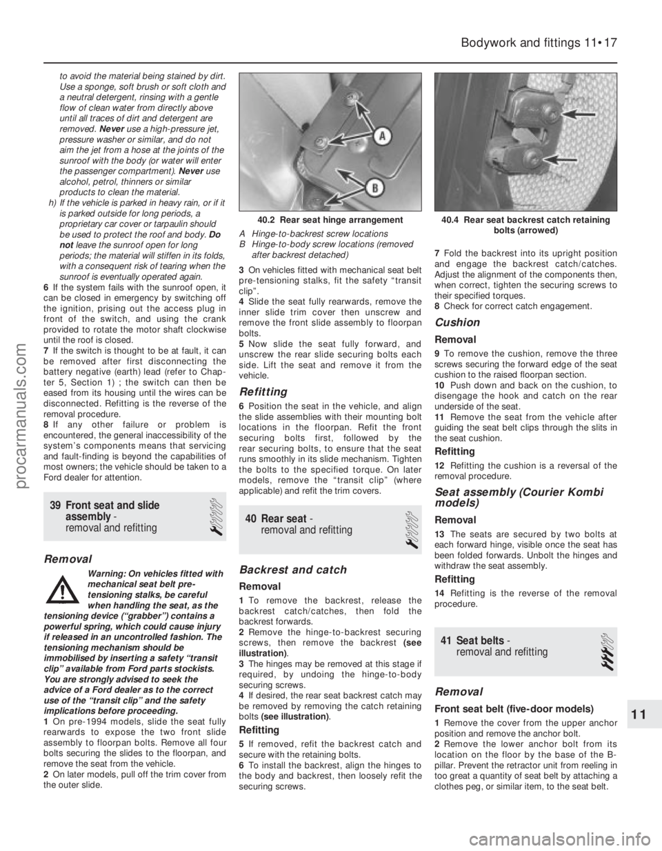
2 Remove the hinge-to-backrest securing
screws, then remove the backrest (see
illustration) .
3 The hinges may be removed at this stage if
required, by undoing the hinge-to-body
securing screws.
4 If desired, the rear seat backrest catch may
be removed by removing the catch retaining
bolts (see illustration) .
Refitting
5If removed, refit the backrest catch and
secure with the retaining bolts.
6 To install the backrest, align the hinges to
the body and backrest, then loosely refit the
securing screws. 7
Fold the backrest into its upright position
and engage the backrest catch/catches.
Adjust the alignment of the components then,
when correct, tighten the securing screws to
their specified torques.
8 Check for correct catch engagement.
Cushion
Removal
9To remove the cushion, remove the three
screws securing the forward edge of the seat
cushion to the raised floorpan section.
10 Push down and back on the cushion, to
disengage the hook and catch on the rear
underside of the seat.
11 Remove the seat from the vehicle after
guiding the seat belt clips through the slits in
the seat cushion.
Refitting
12 Refitting the cushion is a reversal of the
removal procedure.
Seat assembly (Courier Kombi
models)
Removal
13 The seats are secured by two bolts at
each forward hinge, visible once the seat has
been folded forwards. Unbolt the hinges and
withdraw the seat assembly.
Refitting
14 Refitting is the reverse of the removal
procedure.
41 Seat belts -
removal and refitting
3
Removal
Front seat belt (five-door models)
1 Remove the cover from the upper anchor
position and remove the anchor bolt.
2 Remove the lower anchor bolt from its
location on the floor by the base of the B-
pillar. Prevent the retractor unit from reeling in
too great a quantity of seat belt by attaching a
clothes peg, or similar item, to the seat belt.
Bodywork and fittings 11•17
40.4 Rear seat backrest catch retaining bolts (arrowed)40.2 Rear seat hinge arrangement
A Hinge-to-backrest screw locations
B Hinge-to-body screw locations (removed after backrest detached)
11
1595Ford Fiesta Remakeprocarmanuals.com
http://vnx.su