boot FORD FIESTA 1989 Service Repair Manual
[x] Cancel search | Manufacturer: FORD, Model Year: 1989, Model line: FIESTA, Model: FORD FIESTA 1989Pages: 296, PDF Size: 10.65 MB
Page 19 of 296
3Check that the roadwheel nuts are tightened
to the specified torque wrench setting.
4 Refit the wheel covers.
16 Door, tailgate and bonnet
check and lubrication
1
1Check that the doors and tailgate/boot lid
close securely. Check that the bonnet safety
catch operates correctly. Check the operation
of the door check straps.
2 Lubricate the hinges, door check straps,
the striker plates and the bonnet catch
sparingly with a little oil or grease.
17 Seat belt check
1
1 Check the seat belts for satisfactory
operation and condition. Inspect the webbing
for fraying and cuts. Check that they retract
smoothly and without binding into their reels.
2 Check that the seat belt mounting bolts are
tight, and if necessary tighten them to the
specified torque wrench settings as given in
Chapter 11.
18 Bodywork, paint and exterior trim check
1
1The best time to carry out this check is after
the car has been washed so that any surface
blemish or scratch will be clearly evident and
not hidden by a film of dirt.
2 Starting at one front corner check the
paintwork all around the car, looking for minor
scratches or more serious dents. Check all
the trim and make sure that it is securely
attached over its entire length.
3 Check the security of all door locks, door
mirrors, badges, bumpers, front grille and
wheel trim. Anything found loose, or in need of
further attention should be done with reference
to the relevant Chapters of this manual.
4 Rectify any problems noticed with the
paintwork or body panels as described in
Chapter 11.
19 Road test
1
Check the operation and
performance of the braking
system
1 Make sure that the vehicle does not pull to
one side when braking, and that the wheels
do not lock prematurely when braking hard.
2 Check that there is no vibration through the
steering when braking. 3
Check that the handbrake operates
correctly, without excessive movement of the
lever, and that it holds the vehicle stationary
on a slope.
4 Test the operation of the brake servo unit
as follows. With the engine switched off,
depress the footbrake four or five times to
exhaust the vacuum, then hold the pedal
depressed. Start the engine, and there should
be a noticeable “give” in the brake pedal as
vacuum builds up. Allow the engine to run for
at least two minutes, and then switch it off. If
the brake pedal is depressed again, it should
be possible to detect a hiss from the servo as
the pedal is depressed. After about four or five
applications, no further hissing should be
heard, and the pedal should feel considerably
firmer.
Steering and suspension
5 Check for any abnormalities in the steering,
suspension, handling or road “feel”.
6 Drive the vehicle, and check that there are
no unusual vibrations or noises.
7 Check that the steering feels positive, with
no excessive sloppiness or roughness, and
check for any suspension noises when
cornering and driving over bumps.
Drivetrain
8 Check the performance of the engine,
transmission and driveshafts.
9 Check that the engine starts correctly, both
when cold and when hot.
10 Listen for any unusual noises from the
engine and transmission.
11 Make sure that the engine runs smoothly
when idling, and that there is no hesitation
when accelerating.
12 On manual transmission models, check
that all gears can be engaged smoothly
without noise, and that the gear lever action is
not abnormally vague or “notchy”.
13 On automatic transmission models, make
sure that the drive seems smooth without
jerks or engine speed “flare-ups”. Check that
all the gear positions can be selected with the
vehicle at rest. If any problems are found, they
should be referred to a Ford dealer.
14 Listen for a metallic clicking sound from
the front of the vehicle, as the vehicle is driven
slowly in a circle with the steering on full-lock.
Carry out this check in both directions. If a
clicking noise is heard, this indicates wear in a
driveshaft joint, in which case renew the joint
if necessary.
Clutch
15 Check that the clutch pedal moves
smoothly and easily through its full travel, and
that the clutch itself functions correctly, with
no trace of slip or drag. If the movement is
uneven or stiff in places, check that the cable
is routed correctly, with no sharp turns.
16 Inspect both ends of the clutch inner
cable, both at the transmission end and inside
the car, for signs of wear and fraying.
Instruments and electrical
equipment
17 Check the operation of all instruments
and electrical equipment.
18 Make sure that all instruments read
correctly, and switch on all electrical equipment
in turn, to check that it functions properly.
20 Automatic transmission fluid level check
1
1The level of the automatic transmission fluid
should be carefully maintained. Low fluid level
can lead to slipping or loss of drive, while
overfilling can cause foaming, loss of fluid and
transmission damage.
2 The transmission fluid level should only be
checked when the transmission is hot (at its
normal operating temperature). If the vehicle
has just been driven over 10 miles (15 miles in
a cold climate), and the fluid temperature is 60
to 70ºC, the transmission is hot.
Caution: If the vehicle has just been driven
for a long time at high speed or in city
traffic in hot weather, or if it has been
pulling a trailer, an accurate fluid level
reading cannot be obtained. In these
circumstances, allow the fluid to cool
down for about 30 minutes.
3 Park the vehicle on level ground, apply the
handbrake, and start the engine. While the
engine is idling, depress the brake pedal and
move the selector lever through all the gear
positions three times, beginning and ending in
“P”.
4 Allow the engine to idle for one minute, then
(with the engine still idling) remove the
dipstick from its tube. Note the condition and
colour of the fluid on the dipstick.
5 Wipe the fluid from the dipstick with a clean
rag, and re-insert it into the filler tube until the
cap seats.
6 Pull the dipstick out again, and note the
fluid level. The level should be between
the “MIN” and “MAX” marks. If the level is
on the “MIN” mark, stop the engine, and add
the specified automatic transmission fluid
through the dipstick tube, using a clean funnel
if necessary. It is important not to introduce
dirt into the transmission when topping-up.
7 Add the fluid a little at a time, and keep
checking the level as previously described
until it is correct. The difference between the
“MIN” and “MAX” marks on the dipstick is
approximately 0.4 litres.
8 The need for regular topping-up of the
transmission fluid indicates a leak, which
should be found and rectified without delay.
9 The condition of the fluid should also be
checked along with the level. If the fluid on the
dipstick is black or a dark reddish-brown
colour, or if it has a burned smell, the fluid
should be changed. If you are in doubt about
the condition of the fluid, purchase some new
fluid, and compare the two for colour and smell.
1•18Every 10 000 miles or 12 months
1595Ford Fiesta Remakeprocarmanuals.com
http://vnx.su
Page 20 of 296
21 Spark plug renewal and HTcomponent check
1
Note: Spark plug renewal at this service
interval is only necessary on the HCS, CVH
and PTE engines. On Zetec engines, the
recommended interval for spark plug renewal
is every 30 000 miles or three years.
Spark plug check and renewal
1 It is vital for the correct running, full
performance and proper economy of the engine
that the spark plugs perform with maximum
efficiency. The most important factor in ensuring
this is that the plugs fitted are appropriate for the
engine. The suitable type is given in the
Specifications Section at the beginning of this
Chapter, on the Vehicle Emissions Control
Information (VECI) label located on the
underside of the bonnet (only on models sold in
some areas) or in the vehicle’s Owner’s
Handbook. If the correct type is used and the
engine is in good condition, the spark plugs
should not need attention between scheduled
renewal intervals. Spark plug cleaning is rarely
necessary, and should not be attempted unless
specialised equipment is available, as damage
can easily be caused to the firing ends.
2 Spark plug removal and refitting requires a
spark plug socket, with an extension which can
be turned by a ratchet handle or similar. This
socket is lined with a rubber sleeve, to protect
the porcelain insulator of the spark plug, and to
hold the plug while you insert it into the spark
plug hole. You will also need a set of feeler
gauges, to check the spark plug electrode gap,
and a torque wrench to tighten the new plugs
to the specified torque (see illustration).
3 To remove the spark plugs, first open the
bonnet; the plugs are easily reached at the
top of the engine. Note how the spark plug
(HT) leads are routed and secured by clips,
and on some engines, how they’re positioned
along the channel in the cylinder head cover.
To prevent the possibility of mixing up spark
plug (HT) leads, it is a good idea to try to work
on one spark plug at a time.
4 If the marks on the original-equipment spark
plug (HT) leads cannot be seen, mark the leads
1 to 4, to correspond to the cylinder the lead
serves (No 1 cylinder is at the timing belt/chain
end of the engine). Pull the leads from the plugs
by gripping the rubber boot, not the lead,
otherwise the lead connection may be fractured.
5 It is advisable to soak up any liquid in the
spark plug recesses with a rag, and to remove
any dirt from them using a clean brush,
vacuum cleaner or compressed air before
removing the plugs, to prevent any dirt or
water from dropping into the cylinders. Warning: Wear eye protection
when using compressed air!
6 Unscrew the spark plugs, ensuring that the
socket is kept in alignment with each plug - if
the socket is forcibly moved to either side, the
porcelain top of the plug may be broken off. If
any undue difficulty is encountered when
unscrewing any of the spark plugs, carefully
check the cylinder head threads and tapered
sealing surfaces for signs of wear, excessive
corrosion or damage; if any of these
conditions is found, seek the advice of a Ford
dealer as to the best method of repair.
7 As each plug is removed, examine it as
follows - this will give a good indication of the
condition of the engine. If the insulator nose is
covered with light tan to greyish-brown
deposits, then the mixture is correct, and it is
likely that the engine is in good condition.
8 If the tip and insulator nose are covered
with hard black-looking deposits, then this is
indicative that the mixture is too rich. Should
the plug be black and oily, then it is likely that
the engine is fairly worn, as well as the mixture
being too rich.
9 If the insulator nose of the spark plug is clean and white, with no deposits, this is
indicative of a weak mixture.
10
If you are renewing the spark plugs,
purchase the new plugs, then check each of
them first for faults such as cracked insulators
or damaged threads. Note also that,
whenever the spark plugs are renewed as a
routine service operation, the spark plug (HT)
leads should be checked as described below.
11 The spark plug electrode gap is of
considerable importance as, if it is too large or
too small, the size of the spark and its
efficiency will be seriously impaired. The gap
should be set to the value given in the
Specifications Section of this Chapter. New
plugs will not necessarily be set to the correct
gap, so they should always be checked
before fitting.
12 The spark plug gap is correct when the
correct-size feeler gauge or wire gauge is a
firm sliding fit between the electrodes (see
illustrations) .
13 To adjust the electrode gap, bend open, or
close up, the outer plug electrode until the
correct gap is achieved (see illustration). The
centre electrode should never be bent, as this
may crack the insulation and cause plug failure,
Every 20 000 miles (32 000 km) or two years, whichever
comes first
Every 20 000 miles or two years1•19
21.12b Spark plug manufacturers
recommend using a wire-type gauge when
checking the gap - if the wire or feeler gauge
does not slide between the electrodes with a slight drag, adjustment is required
21.12a Measuring a spark plug gap with a feeler gauge21.2 Tools required for changing spark plugs
21.13 To change the gap, bend the outer
electrode only, and be very careful not to crack or chip the porcelain insulator
surrounding the centre electrode
1
1595Ford Fiesta Remakeprocarmanuals.com
http://vnx.su
Page 21 of 296
if nothing worse. If the outer electrode is not
exactly over the centre electrode, bend it gently
to align them. Special spark plug gap adjusting
tools are available from motor accessory shops,
or from certain spark plug manufacturers.
14Before fitting the spark plugs, check that
the threaded connector sleeves at the top of
the plugs are tight, and that the plug exterior
surfaces and threads are clean. Brown
staining on the porcelain, immediately above
the metal body, is quite normal, and does not
necessarily indicate a “leak” between the
body and insulator.
15 Apply a smear of copper-based grease or
anti-seize compound to the threads of each
plug, and screw them in by hand where
possible. Take extra care to enter the plug
threads correctly, as the cylinder head is of
aluminium alloy.
16 When each spark plug is started correctly
on its threads, screw it down until it just seats
lightly, then tighten it to the specified torque
wrench setting. If a torque wrench is not
available - and this is one case where the use of
a torque wrench is strongly recommended -
tighten each spark plug through no more than
1/4 of a turn (CVH and PTE engines) or 1/16 of a
turn (HCS and Zetec engines) after it seats. HCS
and Zetec engines are fitted with taper-seat
spark plugs, identifiable by not having a sealing
washer, and these in particular should NEVER
be overtightened - their tapered seats mean
they are almost impossible to remove if abused.
17 Reconnect the spark plug (HT) leads in
their correct order, using a twisting motion on
the boot until it is firmly seated on the end of
the spark plug and on the cylinder head cover.
Spark plug (HT) lead, distributor
cap and rotor arm check
18 The spark plug (HT) leads should be
checked whenever the plugs themselves are renewed. Start by making a visual check of
the leads while the engine is running. In a
darkened garage (make sure there is
ventilation) start the engine and observe each
lead. Be careful not to come into contact with
any moving engine parts. If there is a break in
the lead, you will see arcing or a small spark
at the damaged area.
19
The spark plug (HT) leads should be
inspected one at a time, to prevent mixing up
the firing order, which is essential for proper
engine operation. Each original lead should
be numbered to identify its cylinder. If the
number is illegible, a piece of tape can be
marked with the correct number, and
wrapped around the lead (the leads should be
numbered 1 to 4, with No 1 lead nearest the
timing belt end of the engine). The lead can
then be disconnected.
20 Check inside the boot for corrosion, which
will look like a white crusty powder. Clean this
off as much as possible; if it is excessive, or if
cleaning leaves the metal connector too badly
eroded to be fit for further use, the lead must
be renewed. Push the lead and boot back
onto the end of the spark plug. The boot
should fit tightly onto the end of the plug - if it
doesn’t, remove the lead and use pliers
carefully to crimp the metal connector inside
the boot until the fit is snug.
21 Using a clean rag, wipe the entire length
of the lead to remove built-up dirt and grease. Once the lead is clean, check for burns,
cracks and other damage. Do not bend the
lead sharply, because the conductor might
break.
22 Disconnect the lead from the ignition coil
by pressing together the plastic retaining
catches (where fitted) and pulling the end
fitting off the coil terminal. Check for corrosion
and for a tight fit. If a meter with the correct
measuring range is available, measure the
resistance of the disconnected lead from its
coil connector to its spark plug connector. If
the resistance recorded for any of the leads
exceeds the value specified, all the leads
should be renewed as a set. Refit the lead to
the coil, noting that each coil terminal is
marked with its respective cylinder number,
so that there is no risk of mixing up the leads
and upsetting the firing order.
23 Inspect the remaining spark plug (HT)
leads, ensuring that each is securely fastened
at the distributor cap or ignition coil and spark
plug when the check is complete. If any sign
of arcing, severe connector corrosion, burns,
cracks or other damage is noticed, obtain new
spark plug (HT) leads, renewing them as a set.
If new spark plug leads are to be fitted,
remove and refit them one at a time, to avoid
mix-ups in the firing order. 24
On models with distributor ignition
systems, refer to Chapter 5B and remove the
distributor cap then thoroughly clean it inside
and out with a dry lint-free rag.
25 Examine the HT lead segments inside the
cap. If they appear badly burned or pitted
renew the cap. Also check the carbon brush
in the centre of the cap, ensuring that it is free
to move and stands proud of its holder. Make
sure that there are no sign of cracks or black
“tracking” lines running down the inside of the
cap, which will also mean renewal if evident.
26 Inspect the rotor arm checking it for
security and also for signs of deterioration as
described above.
27 Refit the cap as described in Chapter 5B
on completion.
22 Idle speed control valve cleaning and maintenance
1
Note: The idle speed control valve may be
mounted on the air cleaner, on the engine
compartment bulkhead, or on the side of the inlet
manifold according to valve make and year of
manufacture. Valves manufactured by Weber are
mounted on the air cleaner and only these valves
require the periodic maintenance described
below. Bulkhead and inlet manifold mounted
valves are manufactured by Hitachi and are
maintenance free. Refer to the warning note in
Section 1 of Chapter 4C before proceeding.
1 Remove the valve as described in Chap-
ter 4C, Section 14.
2 Immerse the valve head in a suitable
container filled with clean petrol, and allow it
to soak for approximately three minutes.
3 Clean the valve bore, slots and piston with
petrol, using a suitable lint-free cloth, then
gently move the piston up and down in its
bore using a small screwdriver (see
illustration) . Ensure that no cloth particles
enter the bore, and do not use the slots to
move the piston.
4 Rinse the valve again with clean petrol, then
dry it using an air line (or other source of
compressed air).
Warning: Wear eye protection
when using compressed air!
5 Clean the mating faces of the valve and the
air filter housing then refit as described in
Chapter 4C, Section 14.
1•20Every 20 000 miles or two years
22.3 Gently move the idle speed control
valve piston up and down in its bore using
a small screwdriver (1.6 litre EFi engine)
1595Ford Fiesta Remake
It’s often difficult to insert spark plugs
into their holes without cross-threading
them. To avoid this possibility, fit a
short piece of rubber hose over the end
of the spark plug. The flexible hose
acts as a universal joint, to help align
the plug with the plug hole. Should the
plug begin to cross-thread, the hose
will slip on the spark plug, preventing
thread damage.
If new spark plug leads are tobe fitted, remove the leads
one at a time and fit each
new lead in exactly the same
position as the old one.
procarmanuals.com
http://vnx.su
Page 271 of 296
1595 Ford Fiesta Remake
The jack supplied with the vehicle tool kit
should only be used for changing the
roadwheels - see “Wheel changing” at the
front of this manual. When jacking up the
vehicle to carry out repair or maintenance
tasks, a pillar or trolley type jack of suitable
lifting capacity must be used, supplemented
with axle stands positioned only beneath the
appropriate points under the vehicle (see
illustration) . Note that the vehicle must never
be jacked up at the rear under the axle beam. The maximum kerb weight of the vehicle must
not be exceeded when jacking and supporting
the vehicle. Do not under any circumstances
jack up the rear of the vehicle under the rear axle.
Never work under, around or near a raised
vehicle unless it is adequately supported in at
least two places with axle stands.
The radio/cassette unit fitted as standard or
optional equipment may be equipped with a
built-in security code, to deter thieves. If the
power source to the unit is cut, the anti-theft
system will activate. Even if the power source
is immediately reconnected, the radio/
cassette unit will not function until the correct security code has been entered. Therefore,
if you do not know the correct security
code for the radio/cassette unit do not
disconnect either of the battery terminals, or
remove the radio/cassette unit from the
vehicle. To enter the correct security code, follow the instructions provided with the
radio/cassette player or vehicle handbook.
If an incorrect code is entered, the unit will
become locked, and cannot be operated.
If this happens, or if the security code is lost
or forgotten, seek the advice of your Ford
dealer.
Jacking and vehicle supportREF•5
REF
Radio/cassette unit anti-theft system - precaution
Underside view of the vehicle showing the jacking point locations
A Jacking points for trolley jack (always use a suitable block
of wood to protect the
vehicle body)
B Axle stand positions
C Jacking points for owner jack and wheel-free hoist
Buying spare parts
Spare parts are available from many
sources, including maker’s appointed
garages, accessory shops, and motor factors.
To be sure of obtaining the correct parts, it
will sometimes be necessary to quote the
vehicle identification number. If possible, it
can also be useful to take the old parts along
for positive identification. Items such as
starter motors and alternators may be
available under a service exchange scheme -
any parts returned should always be clean.
Our advice regarding spare part sources is
as follows.
Officially-appointed garages
This is the best source of parts which are
peculiar to your car, and which are not
otherwise generally available (eg badges,
interior trim, certain body panels, etc). It is
also the only place at which you should buy
parts if the vehicle is still under warranty.
Accessory shops
These are very good places to buy materials and components needed for the
maintenance of your car (oil, air and fuel
filters, spark plugs, light bulbs, drivebelts, oils
and greases, brake pads, touch-up paint, etc).
Components of this nature sold by a
reputable shop are of the same standard as
those used by the car manufacturer.
Besides components, these shops also sell
tools and general accessories, usually have
convenient opening hours, charge lower
prices, and can often be found not far from
home. Some accessory shops have parts
counters where the components needed for
almost any repair job can be purchased or
ordered.
Motor factors
Good factors will stock all the more
important components which wear out
comparatively quickly, and can sometimes
supply individual components needed for the
overhaul of a larger assembly (eg brake seals
and hydraulic parts, bearing shells, pistons,
valves, alternator brushes). They may also
handle work such as cylinder block reboring,
crankshaft regrinding and balancing, etc.
Tyre and exhaust specialists
These outlets may be independent, or
members of a local or national chain. They
frequently offer competitive prices when
compared with a main dealer or local garage,
but it will pay to obtain several quotes before
making a decision. When researching prices,
also ask what “extras” may be added - for
instance, fitting a new valve and balancing the
wheel are both commonly charged on top of
the price of a new tyre.
Other sources
Beware of parts or materials obtained from
market stalls, car boot sales or similar outlets.
Such items are not invariably sub-standard,
but there is little chance of compensation if
they do prove unsatisfactory. In the case of
safety-critical components such as brake
pads, there is the risk not only of financial loss
but also of an accident causing injury or
death. Second-hand components or assemblies
obtained from a car breaker can be a good
buy in some circumstances, but this sort of
purchase is best made by the experienced
DIY mechanic.
Buying spare parts
procarmanuals.com
http://vnx.su
Page 281 of 296
1595 Ford Fiesta Remake
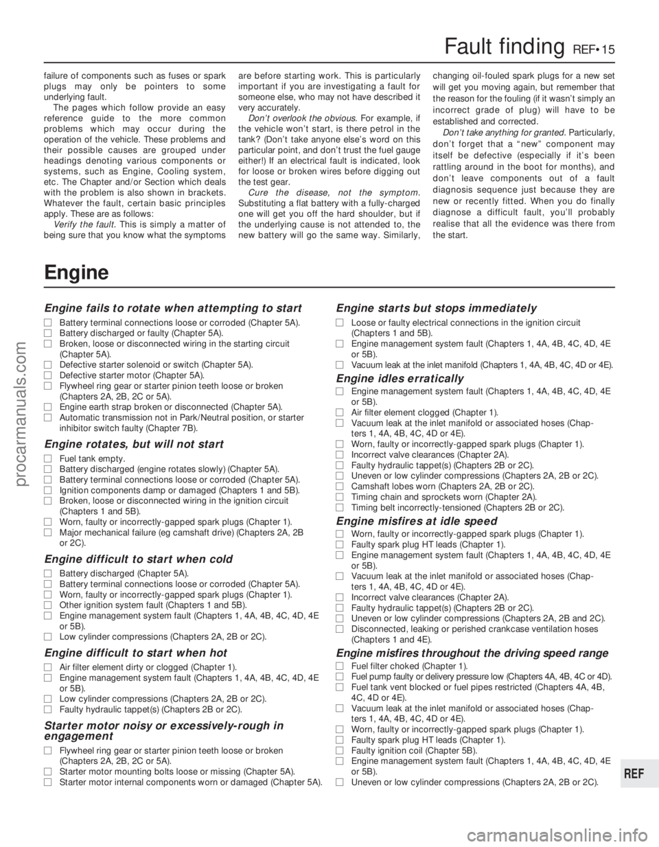
failure of components such as fuses or spark
plugs may only be pointers to some
underlying fault.
The pages which follow provide an easy
reference guide to the more common
problems which may occur during the
operation of the vehicle. These problems and
their possible causes are grouped under
headings denoting various components or
systems, such as Engine, Cooling system,
etc. The Chapter and/or Section which deals
with the problem is also shown in brackets.
Whatever the fault, certain basic principles
apply. These are as follows:
Verify the fault . This is simply a matter of
being sure that you know what the symptoms are before starting work. This is particularly
important if you are investigating a fault for
someone else, who may not have described it
very accurately.
Don’t overlook the obvious . For example, if
the vehicle won’t start, is there petrol in the
tank? (Don’t take anyone else’s word on this
particular point, and don’t trust the fuel gauge
either!) If an electrical fault is indicated, look
for loose or broken wires before digging out
the test gear. Cure the disease, not the symptom .
Substituting a flat battery with a fully-charged
one will get you off the hard shoulder, but if
the underlying cause is not attended to, the
new battery will go the same way. Similarly, changing oil-fouled spark plugs for a new set
will get you moving again, but remember that
the reason for the fouling (if it wasn’t simply an
incorrect grade of plug) will have to be
established and corrected.
Don’t take anything for granted . Particularly,
don’t forget that a “new” component may
itself be defective (especially if it’s been
rattling around in the boot for months), and
don’t leave components out of a fault
diagnosis sequence just because they are
new or recently fitted. When you do finally
diagnose a difficult fault, you’ll probably
realise that all the evidence was there from
the start.
Fault findingREF•15
REF
Engine
Engine fails to rotate when attempting to start
m
m Battery terminal connections loose or corroded (Chapter 5A).
m
m Battery discharged or faulty (Chapter 5A).
m
m Broken, loose or disconnected wiring in the starting circuit
(Chapter 5A).
m m Defective starter solenoid or switch (Chapter 5A).
m
m Defective starter motor (Chapter 5A).
m
m Flywheel ring gear or starter pinion teeth loose or broken
(Chapters 2A, 2B, 2C or 5A).
m m Engine earth strap broken or disconnected (Chapter 5A).
m
m Automatic transmission not in Park/Neutral position, or starter
inhibitor switch faulty (Chapter 7B).
Engine rotates, but will not start
m mFuel tank empty.
m
m Battery discharged (engine rotates slowly) (Chapter 5A).
m
m Battery terminal connections loose or corroded (Chapter 5A).
m
m Ignition components damp or damaged (Chapters 1 and 5B).
m
m Broken, loose or disconnected wiring in the ignition circuit
(Chapters 1 and 5B).
m m Worn, faulty or incorrectly-gapped spark plugs (Chapter 1).
m
m Major mechanical failure (eg camshaft drive) (Chapters 2A, 2B
or 2C).
Engine difficult to start when cold
m mBattery discharged (Chapter 5A).
m
m Battery terminal connections loose or corroded (Chapter 5A).
m
m Worn, faulty or incorrectly-gapped spark plugs (Chapter 1).
m
m Other ignition system fault (Chapters 1 and 5B).
m
m Engine management system fault (Chapters 1, 4A, 4B, 4C, 4D, 4E
or 5B).
m m Low cylinder compressions (Chapters 2A, 2B or 2C).
Engine difficult to start when hot
m
mAir filter element dirty or clogged (Chapter 1).
m
m Engine management system fault (Chapters 1, 4A, 4B, 4C, 4D, 4E
or 5B).
m m Low cylinder compressions (Chapters 2A, 2B or 2C).
m
m Faulty hydraulic tappet(s) (Chapters 2B or 2C).
Starter motor noisy or excessively-rough in
engagement
m mFlywheel ring gear or starter pinion teeth loose or broken
(Chapters 2A, 2B, 2C or 5A).
m m Starter motor mounting bolts loose or missing (Chapter 5A).
m
m Starter motor internal components worn or damaged (Chapter 5A).
Engine starts but stops immediately
m
mLoose or faulty electrical connections in the ignition circuit
(Chapters 1 and 5B).
m m Engine management system fault (Chapters 1, 4A, 4B, 4C, 4D, 4E
or 5B).
m m Vacuum leak at the inlet manifold (Chapters 1, 4A, 4B, 4C, 4D or 4E).
Engine idles erratically
m
mEngine management system fault (Chapters 1, 4A, 4B, 4C, 4D, 4E
or 5B).
m m Air filter element clogged (Chapter 1).
m
m Vacuum leak at the inlet manifold or associated hoses (Chap-
ters 1, 4A, 4B, 4C, 4D or 4E).
m m Worn, faulty or incorrectly-gapped spark plugs (Chapter 1).
m
m Incorrect valve clearances (Chapter 2A).
m
m Faulty hydraulic tappet(s) (Chapters 2B or 2C).
m
m Uneven or low cylinder compressions (Chapters 2A, 2B or 2C).
m
m Camshaft lobes worn (Chapters 2A, 2B or 2C).
m
m Timing chain and sprockets worn (Chapter 2A).
m
m Timing belt incorrectly-tensioned (Chapters 2B or 2C).
Engine misfires at idle speed
m
mWorn, faulty or incorrectly-gapped spark plugs (Chapter 1).
m
m Faulty spark plug HT leads (Chapter 1).
m
m Engine management system fault (Chapters 1, 4A, 4B, 4C, 4D, 4E
or 5B).
m m Vacuum leak at the inlet manifold or associated hoses (Chap-
ters 1, 4A, 4B, 4C, 4D or 4E).
m m Incorrect valve clearances (Chapter 2A).
m
m Faulty hydraulic tappet(s) (Chapters 2B or 2C).
m
m Uneven or low cylinder compressions (Chapters 2A, 2B and 2C).
m
m Disconnected, leaking or perished crankcase ventilation hoses
(Chapters 1 and 4E).
Engine misfires throughout the driving speed range
m mFuel filter choked (Chapter 1).
m
m Fuel pump faulty or delivery pressure low (Chapters 4A, 4B, 4C or 4D).\
m
m Fuel tank vent blocked or fuel pipes restricted (Chapters 4A, 4B,
4C, 4D or 4E).
m m Vacuum leak at the inlet manifold or associated hoses (Chap-
ters 1, 4A, 4B, 4C, 4D or 4E).
m m Worn, faulty or incorrectly-gapped spark plugs (Chapter 1).
m
m Faulty spark plug HT leads (Chapter 1).
m
m Faulty ignition coil (Chapter 5B).
m
m Engine management system fault (Chapters 1, 4A, 4B, 4C, 4D, 4E
or 5B).
m m Uneven or low cylinder compressions (Chapters 2A, 2B or 2C).
procarmanuals.com
http://vnx.su
Page 293 of 296
1595 Ford Fiesta Remake
IndexREF•27
REF
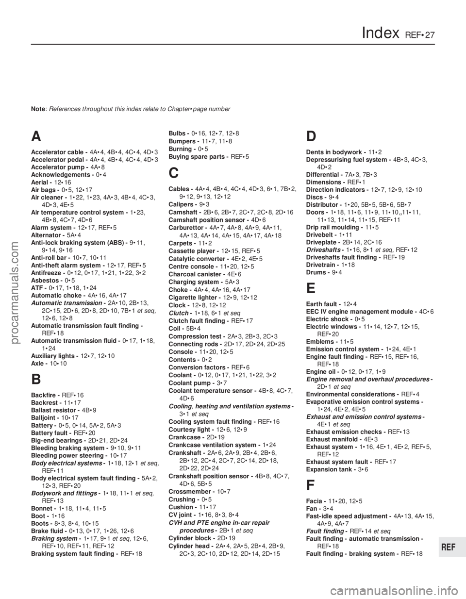
Note: References throughout this index relate to Chapter•page number
A
Accelerator cable -4A•4, 4B•4, 4C•4, 4D•3
Accelerator pedal - 4A•4, 4B•4, 4C•4, 4D•3
Accelerator pump - 4A•8
Acknowledgements - 0•4
Aerial - 12•16
Air bags - 0•5, 12•17
Air cleaner - 1•22, 1•23, 4A•3, 4B•4, 4C•3,
4D•3, 4E•5
Air temperature control system - 1•23,
4B•8, 4C•7, 4D•6
Alarm system - 12•17, REF• 5
Alternator - 5A•4
Anti-lock braking system (ABS) - 9•11,
9•14, 9•16
Anti-roll bar - 10•7, 10•11
Anti-theft alarm system - 12•17, REF•5
Antifreeze - 0•12, 0•17, 1•21, 1•22, 3•2
Asbestos - 0•5
ATF - 0•17, 1•18, 1•24
Automatic choke - 4A•16, 4A•17
Automatic transmission -2A•10, 2B•13,
2C•15, 2D•6, 2D•8, 2D•10, 7B•1 et seq,
12 •6, 12 •8
Automatic transmission fault finding - REF• 18
Automatic transmission fluid - 0•17, 1•18,
1•24
Auxiliary lights - 12•7, 12•10
Axle - 10•10
B
Backfire - REF•16
Backrest - 11•17
Ballast resistor - 4B•9
Balljoint - 10•17
Battery - 0•5, 0•14, 5A•2, 5A•3
Battery fault - REF•20
Big-end bearings - 2D•21, 2D•24
Bleeding braking system - 9•10, 9•11
Bleeding power steering - 10•17
Body electrical systems -1•18, 12 •1et seq,
REF• 11
Body electrical system fault finding - 5A•2,
12 •3, REF •20
Bodywork and fittings -1•18, 11 •1et seq,
REF• 13
Bonnet - 1•18, 11•4,11•5
Boot - 1•16
Boots - 8•3, 8•4, 10 •15
Brake fluid - 0•13, 0•17, 1•26, 12 •6
Braking system -1•17, 9•1 et seq, 12•6,
REF• 10, REF•11, REF• 12
Braking system fault finding - REF•18 Bulbs -
0•16, 12 •7,12•8
Bumpers - 11•7, 11•8
Burning - 0•5
Buying spare parts - REF•5
C
Cables -4A•4, 4B•4, 4C•4, 4D•3, 6•1, 7B•2,
9•12, 9•13, 12 •12
Calipers - 9•3
Camshaft - 2B•6, 2B•7, 2C•7, 2C•8, 2D•16
Camshaft position sensor - 4D•6
Carburettor - 4A•7, 4A•8, 4A•9, 4A•11,
4A•13, 4A•14, 4A•15, 4A•17, 4A•18
Carpets - 11•2
Cassette player - 12•15, REF •5
Catalytic converter - 4E•2, 4E•5
Centre console - 11•20, 12 •5
Charcoal canister - 4E•6
Charging system - 5A•3
Choke - 4A•4, 4A•16, 4A•17
Cigarette lighter - 12•9, 12 •12
Clock - 12•8, 12•12
Clutch -1•18, 6•1 et seq
Clutch fault finding - REF•17
Coil - 5B•4
Compression test - 2A•3, 2B•3, 2C•3
Connecting rods - 2D•17, 2D•24, 2D•25
Console - 11•20, 12•5
Contents - 0•2
Conversion factors - REF•6
Coolant - 0•12, 0•17, 1•21, 1•22, 3•2
Coolant pump - 3•7
Coolant temperature sensor - 4B•8, 4C•7,
4D•6
Cooling ,heating and ventilation systems -
3•1 et seq
Cooling system fault finding - REF•16
Courtesy light - 12•6, 12•9
Crankcase - 2D•19
Crankcase ventilation system - 1•24
Crankshaft - 2A•6, 2A•9, 2B•4, 2B•6,
2B•12, 2C•4, 2C•7, 2C•14, 2D•18,
2D•22, 2D•24
Crankshaft position sensor - 4B•8, 4C•7,
4D•6, 5B•5
Crossmember - 10•7
Crushing - 0•5
Cushion - 11•17
CV joint - 1•16, 8•3, 8•4
CVH and PTE engine in-car repair
procedures -2B•1 et seq
Cylinder block - 2D•19
Cylinder head - 2A•4, 2A•5, 2B•4, 2B•9,
2C•3, 2C•10, 2D•12, 2D•14, 2D•15
D
Dents in bodywork - 11•2
Depressurising fuel system - 4B•3, 4C•3,
4D•2
Differential - 7A•3, 7B•3
Dimensions - REF•1
Direction indicators - 12•7, 12•9, 12•10
Discs - 9•4
Distributor - 1•20, 5B•5, 5B•6, 5B•7
Doors - 1•18, 11• 6,11•9, 11 •10,,11 •11,
11 •13, 11•14, 11•15, REF •11
Drip rail moulding - 11•5
Drivebelt - 1•11
Driveplate - 2B•14, 2C•16
Driveshafts -1•16, 8•1 et seq,REF•12
Driveshafts fault finding - REF•19
Drivetrain - 1•18
Drums - 9•4
E
Earth fault - 12•4
EEC IV engine management module - 4C•6
Electric shock - 0•5
Electric windows - 11•14, 12 •7, 12•15,
REF•20
Emblems - 11•5
Emission control system - 1•24, 4E•1
Engine fault finding - REF•15, REF•16,
REF •18
Engine oil - 0•12, 0•17, 1•9
Engine removal and overhaul procedures -
2D•1 et seq
Environmental considerations - REF•4
Evaporative emission control systems - 1•24, 4E•2, 4E•5
Exhaust and emission control systems -
4E•1 et seq
Exhaust emission checks - REF•13
Exhaust manifold - 4E•3
Exhaust system - 1•16, 4E•1, 4E•2, REF •5,
REF •12
Exhaust system fault - REF•17
Expansion tank - 3•6
F
Facia - 11•20, 12 •5
Fan - 3•4
Fast-idle speed adjustment - 4A•13, 4A•15,
4A•9, 4A•7
Fault finding - REF•14et seq
Fault finding - automatic transmission -
REF •18
Fault finding - braking system - REF•18
procarmanuals.com
http://vnx.su
Page 295 of 296
R
Radiator -3•6
Radiator fan - 3•4
Radiator grille - 11•7
Radio - 12•15, REF •5
Rear axle - 10•10
Rear light cluster - 12•7, 12•8, 12 •10
Regulator (window) - 11•14
Relays - 12•4
Release bearing - 6•4
Repair procedures - REF•4
Respraying - 11•3
Reversing light - 7A•4, 12•6
Ride height - 10•12
Road test - 1•18
Roadside repairs -0•6 et seq
Roadwheels - 1•15, 1•16, 1•17
Rocker arms - 2B•7
Rocker cover - 2B•4
Rocker gear - 2A•4
Roof drip rail moulding - 11•5
Rotor arm - 1•20, 5B•5
Routine maintenance and servicing -1•1
et seq
Routine maintenance - bodywork and
underframe - 11•2
Routine maintenance - upholstery and carpets - 11•2
Rubber boots - 1•16, 8•3, 8•4, 10 •15
Rust holes in bodywork - 11•3
S
Safety first - 0•5
Scalding - 0•5
Screw threads and fastenings - REF•4
Seat belts - 1•18, 11•17, REF•11
Seats - 11•17, REF •11
Selector - 7B•2, 12•8
Servo - 9•9, 9•11, 9•12
Shock absorbers - 10•11, REF •11, REF•12
Shoes - 9•5
Short-circuit - 12•4
Sidelight - 12•7
Sill moulding - 11•6
Sill scuff plate - 11•19
Spark plug - 1•19
Speakers - 12•16 Speedometer -
7A•3, 7B•3, 12•11, 12•12
Spoiler - 11•12
Springs - REF•12
Starter inhibitor switch - 7B•4, 12•6
Starter motor - 5A•7
Starter motor fault - REF•15
Starting and charging systems -5A•1 et
seq
Steering - See Suspension and steering
Stop-light switch - 12•6
Struts - 10•6, 10• 9
Sump - 2A•7, 2B•10, 2C•12
Sunroof - 11•16
Suspension and steering -1•15, 1•18, 10 •1
et seq, 12•5, REF •10, REF •11, REF• 12
Suspension and steering fault finding -
REF •19
Switches - 3•5, 4B•5, 4B•8, 4C•5, 4C•7,
4D•4, 4D•7, 7A•4, 7B•4, 9•16, 12 •5
T
Tachometer - 12•12
Tailgate - 1•18, 11•12, 11•16, 12•15, 2B•7,
2C•8, 2D•16
Temperature gauge - 3•5, 12•12
Temperature gauge fault - REF•20
Thermostat - 3•3
Throttle housing - 4C•6, 4D•4
Throttle kicker unit - 4A•10, 4A•11,
4A•13
Throttle plate control motor - 4B•7
Throttle position sensor - 4B•8, 4C•7,
4D•6
Timing - 5B•7
Timing belt - 1•25, 2B•5, 2B•6, 2C•5, 2C•7
Timing chain - 2A•6, 2A•7
Tools - REF•4, REF•7, REF•9
Top Dead Centre (TDC) for No 1 piston - 2A•3, 2B•3, 2C•3
Towing - 0•9
Track rod end - 10•17
Trim - 1•18
Trim panels - 11•5, 11 •6, 11•8, 11 •10,
11 •12, 11•13, 11•19, 11•20
Turbocharger - 4C•8, 4C•9
Tyres - 0•15, REF•5, REF •13
Tyre fault - REF•19
Tyre pressures - 0•18
U
Underbody -1•17
Underframe - 11•2
Upholstery - 11•2
V
Vacuum hoses - 1•13
Vacuum servo - 9•9, 9•11, 9•12
Valve clearance - 1•14, 2A•4, 2B•4, 2C•4
Valves - 2D•14, 2D•15
Vehicle identification - REF•3, REF •11
Vehicle speed sensor - 4B•8, 4C•7, 4D•7
Vehicle support - REF•5
Ventilation components - 3•2, 3•8
Voltage regulator - 5A•4
W
Warning lights - 12•8, 12•11
Washer system - 0•14, 12•14, 12•15
Washers fault - REF•20
Water pump - 3•7
Weatherseal - 11•6, 11•16
Weekly checks -0•10 et seq
Weights - REF•2
Wheel alignment - 1•25, 10•17
Wheel bearings - 10•5, 10 •8, REF •12
Wheel changing - 0•8
Wheel cylinders - 9•6
Wheelarch liners - 11•6
Wheels - REF•13
Wheels locking - REF•18
Wind deflector - 11•7
Windows - 11•14, 11•15, 12 •7, 12•15,
REF•20
Windscreen - 11•16, REF •10
Wipers - 0•16, 12• 12, 12•13, 12•14
Wipers fault - REF•20
Wiring check - 1•13
Wiring diagrams - 12•19 et seq
Working facilities - REF•9
Z
Zetec engine in-car repair procedures -
2C•1 et seq
IndexREF•29
REF
1595 Ford Fiesta Remakeprocarmanuals.com
http://vnx.su