jacking points FORD FIESTA 1989 Service Repair Manual
[x] Cancel search | Manufacturer: FORD, Model Year: 1989, Model line: FIESTA, Model: FORD FIESTA 1989Pages: 296, PDF Size: 10.65 MB
Page 22 of 296
23 Coolant renewal
1
Note: If the antifreeze used is Ford’s own, the
coolant need not be renewed for the life of the
vehicle. If the vehicle’s history is unknown, if
antifreeze of lesser quality is known to be in
the system, or simply if you prefer to follow
conventional servicing intervals, the coolant
should be changed periodically (typically,
every 3 years) as described here. Refer also to
“Antifreeze - notes on renewal” in this
Section.
Warning: Do not allow
antifreeze to come in contact
with your skin or painted
surfaces of the vehicle. Flush
contaminated areas immediately with
plenty of water. Don’t store new coolant,
or leave old coolant lying around, where
it’s accessible to children or pets - they’re
attracted by its sweet smell. Ingestion of
even a small amount of coolant can be
fatal! Wipe up garage-floor and drip-pan
spills immediately. Keep antifreeze
containers covered, and repair cooling
system leaks as soon as they’re noticed.
Warning: Never remove the expansion
tank filler cap when the engine is running,
or has just been switched off, as the
cooling system will be hot, and the
consequent escaping steam and scalding
coolant could cause serious injury.
Coolant draining
Warning: Wait until the engine is
cold before starting this
procedure.
1 To drain the system, first remove the
expansion tank filler cap (see “Weekly
Checks” ).
2 If additional working clearance is required,
raise the front of the vehicle and support it securely on axle stands (see
“Jacking and
Vehicle Support” ).
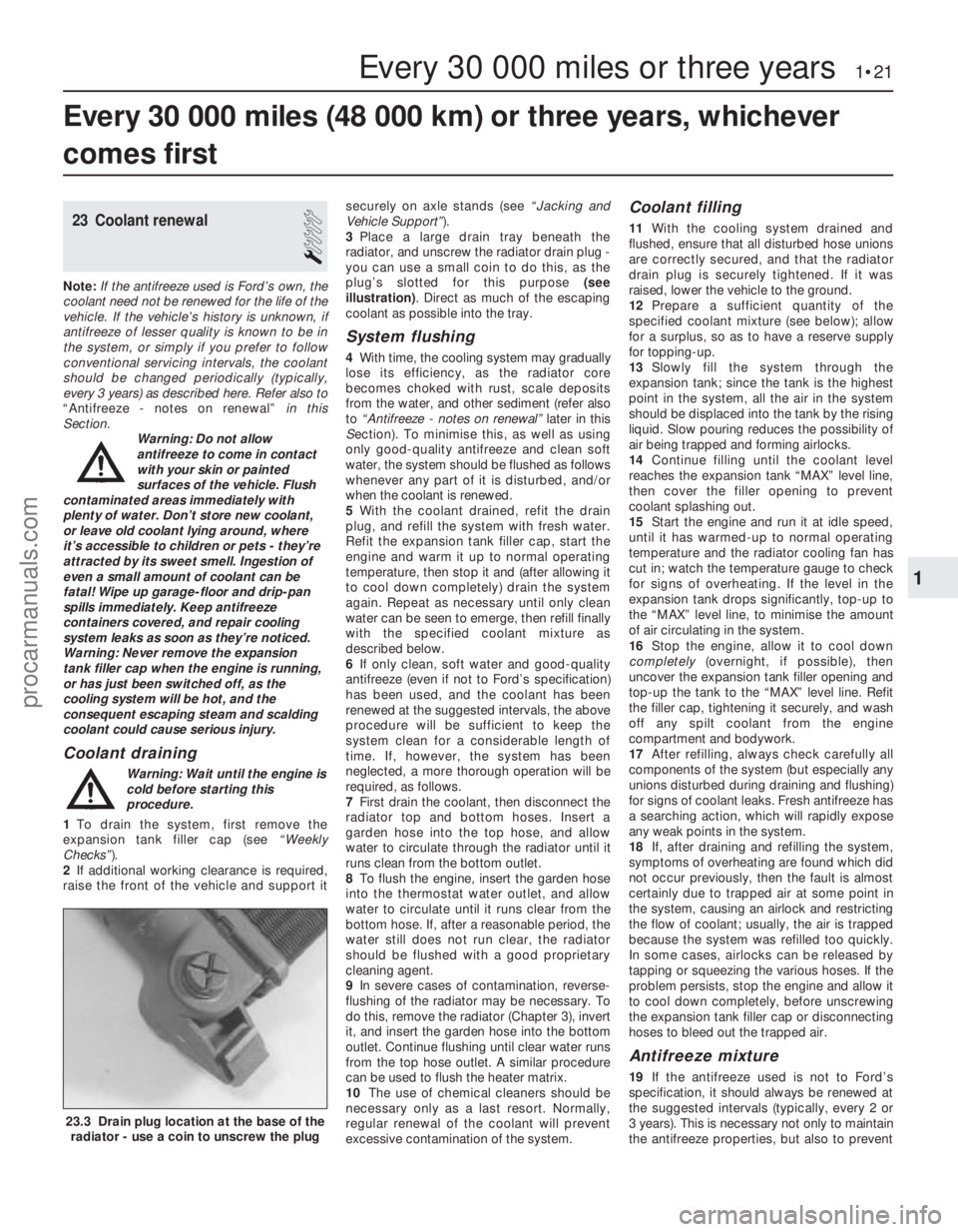
3 Place a large drain tray beneath the
radiator, and unscrew the radiator drain plug -
you can use a small coin to do this, as the
plug’s slotted for this purpose (see
illustration) . Direct as much of the escaping
coolant as possible into the tray.
System flushing
4 With time, the cooling system may gradually
lose its efficiency, as the radiator core
becomes choked with rust, scale deposits
from the water, and other sediment (refer also
to “Antifreeze - notes on renewal” later in this
S ection). To minimise this, as well as using
only good-quality antifreeze and clean soft
water, the system should be flushed as follows
whenever any part of it is disturbed, and/or
when the coolant is renewed.
5 With the coolant drained, refit the drain
plug, and refill the system with fresh water.
Refit the expansion tank filler cap, start the
engine and warm it up to normal operating
temperature, then stop it and (after allowing it
to cool down completely) drain the system
again. Repeat as necessary until only clean
water can be seen to emerge, then refill finally
with the specified coolant mixture as
described below.
6 If only clean, soft water and good-quality
antifreeze (even if not to Ford’s specification)
has been used, and the coolant has been
renewed at the suggested intervals, the above
procedure will be sufficient to keep the
system clean for a considerable length of
time. If, however, the system has been
neglected, a more thorough operation will be
required, as follows.
7 First drain the coolant, then disconnect the
radiator top and bottom hoses. Insert a
garden hose into the top hose, and allow
water to circulate through the radiator until it
runs clean from the bottom outlet.
8 To flush the engine, insert the garden hose
into the thermostat water outlet, and allow
water to circulate until it runs clear from the
bottom hose. If, after a reasonable period, the
water still does not run clear, the radiator
should be flushed with a good proprietary
cleaning agent.
9 In severe cases of contamination, reverse-
flushing of the radiator may be necessary. To
do this, remove the radiator (Chapter 3), invert
it, and insert the garden hose into the bottom
outlet. Continue flushing until clear water runs
from the top hose outlet. A similar procedure
can be used to flush the heater matrix.
10 The use of chemical cleaners should be
necessary only as a last resort. Normally,
regular renewal of the coolant will prevent
excessive contamination of the system.
Coolant filling
11 With the cooling system drained and
flushed, ensure that all disturbed hose unions
are correctly secured, and that the radiator
drain plug is securely tightened. If it was
raised, lower the vehicle to the ground.
12 Prepare a sufficient quantity of the
specified coolant mixture (see below); allow
for a surplus, so as to have a reserve supply
for topping-up.
13 Slowly fill the system through the
expansion tank; since the tank is the highest
point in the system, all the air in the system
should be displaced into the tank by the rising
liquid. Slow pouring reduces the possibility of
air being trapped and forming airlocks.
14 Continue filling until the coolant level
reaches the expansion tank “MAX” level line,
then cover the filler opening to prevent
coolant splashing out.
15 Start the engine and run it at idle speed,
until it has warmed-up to normal operating
temperature and the radiator cooling fan has
cut in; watch the temperature gauge to check
for signs of overheating. If the level in the
expansion tank drops significantly, top-up to
the “MAX” level line, to minimise the amount
of air circulating in the system.
16 Stop the engine, allow it to cool down
completely (overnight, if possible), then
uncover the expansion tank filler opening and
top-up the tank to the “MAX” level line. Refit
the filler cap, tightening it securely, and wash
off any spilt coolant from the engine
compartment and bodywork.
17 After refilling, always check carefully all
components of the system (but especially any
unions disturbed during draining and flushing)
for signs of coolant leaks. Fresh antifreeze has
a searching action, which will rapidly expose
any weak points in the system.
18 If, after draining and refilling the system,
symptoms of overheating are found which did
not occur previously, then the fault is almost
certainly due to trapped air at some point in
the system, causing an airlock and restricting
the flow of coolant; usually, the air is trapped
because the system was refilled too quickly.
In some cases, airlocks can be released by
tapping or squeezing the various hoses. If the
problem persists, stop the engine and allow it
to cool down completely, before unscrewing
the expansion tank filler cap or disconnecting
hoses to bleed out the trapped air.
Antifreeze mixture
19 If the antifreeze used is not to Ford’s
specification, it should always be renewed at
the suggested intervals (typically, every 2 or
3 years). This is necessary not only to maintain
the antifreeze properties, but also to prevent
Every 30 000 miles (48 000 km) or three years, whichever
comes first
Every 30 000 miles or three years 1•21
23.3 Drain plug location at the base of the radiator - use a coin to unscrew the plug
1
1595Ford Fiesta Remakeprocarmanuals.com
http://vnx.su
Page 26 of 296
the specified type of fluid. It is essential that
no dirt is introduced into the transmission
during this operation.
7Depending on the extent to which the fluid
was allowed to drain, it is possible that the
amount of fluid required when filling the
transmission may be more than the specified
amount (see “Lubricants, fluids and tyre
pressures” ). However, due to fluid remaining in
the system, it is more likely that less than the
specified amount will be required. Add about
half the specified amount, then run the engine
up to its normal operating temperature and
check the level on the dipstick. When the level
approaches the maximum mark, proceed as
detailed in Section 20 to check the level and
complete the final topping-up as described.
27 Handbrake adjustment
3
1 Chock the front wheels then jack up the
rear of the car and support it on axle stands
(see “Jacking and Vehicle Support” ). Fully
release the handbrake.
2 Check that the handbrake cables are
correctly routed and secured by the retaining
clips at the appropriate points under the vehicle.
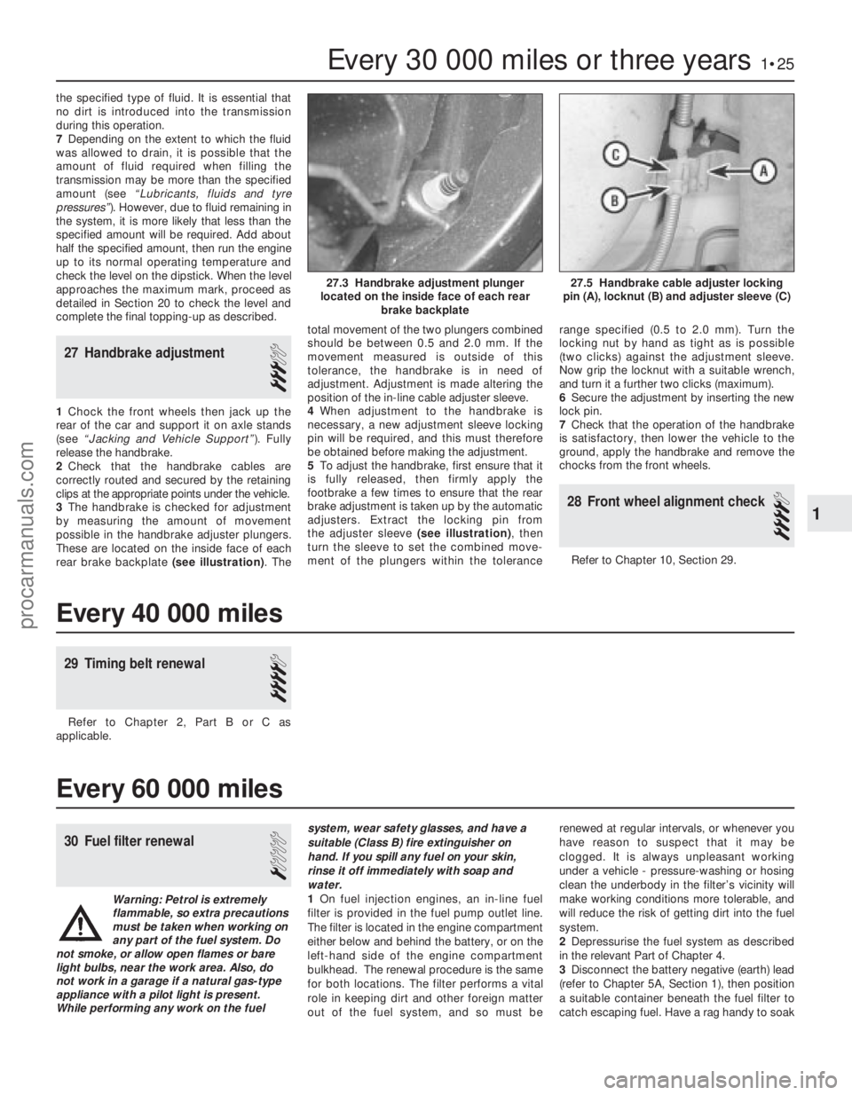
3 The handbrake is checked for adjustment
by measuring the amount of movement
possible in the handbrake adjuster plungers.
These are located on the inside face of each
rear brake backplate (see illustration) . Thetotal movement of the two plungers combined
should be between 0.5 and 2.0 mm. If the
movement measured is outside of this
tolerance, the handbrake is in need of
adjustment. Adjustment is made altering the
position of the in-line cable adjuster sleeve.
4
When adjustment to the handbrake is
necessary, a new adjustment sleeve locking
pin will be required, and this must therefore
be obtained before making the adjustment.
5 To adjust the handbrake, first ensure that it
is fully released, then firmly apply the
footbrake a few times to ensure that the rear
brake adjustment is taken up by the automatic
adjusters. Extract the locking pin from
the adjuster sleeve (see illustration), then
turn the sleeve to set the combined move-
ment of the plungers within the tolerance range specified (0.5 to 2.0 mm). Turn the
locking nut by hand as tight as is possible
(two clicks) against the adjustment sleeve.
Now grip the locknut with a suitable wrench,
and turn it a further two clicks (maximum).
6
Secure the adjustment by inserting the new
lock pin.
7 Check that the operation of the handbrake
is satisfactory, then lower the vehicle to the
ground, apply the handbrake and remove the
chocks from the front wheels.
28 Front wheel alignment check
4
Refer to Chapter 10, Section 29.
Every 30 000 miles or three years1•25
27.5 Handbrake cable adjuster locking
pin (A), locknut (B) and adjuster sleeve (C)27.3 Handbrake adjustment plunger
located on the inside face of each rear brake backplate
1
1595Ford Fiesta Remake
Every 40 000 miles
29 Timing belt renewal
4
Refer to Chapter 2, Part B or C as
applicable.
Every 60 000 miles
30 Fuel filter renewal
1
Warning: Petrol is extremely
flammable, so extra precautions
must be taken when working on
any part of the fuel system. Do
not smoke, or allow open flames or bare
light bulbs, near the work area. Also, do
not work in a garage if a natural gas-type appliance with a pilot light is present.
While performing any work on the fuel system, wear safety glasses, and have a
suitable (Class B) fire extinguisher on
hand. If you spill any fuel on your skin,
rinse it off immediately with soap and
water.
1
On fuel injection engines, an in-line fuel
filter is provided in the fuel pump outlet line.
The filter is located in the engine compartment
either below and behind the battery, or on the
left-hand side of the engine compartment
bulkhead. The renewal procedure is the same
for both locations. The filter performs a vital
role in keeping dirt and other foreign matter
out of the fuel system, and so must be renewed at regular intervals, or whenever you
have reason to suspect that it may be
clogged. It is always unpleasant working
under a vehicle - pressure-washing or hosing
clean the underbody in the filter’s vicinity will
make working conditions more tolerable, and
will reduce the risk of getting dirt into the fuel
system.
2
Depressurise the fuel system as described
in the relevant Part of Chapter 4.
3 Disconnect the battery negative (earth) lead
(refer to Chapter 5A, Section 1), then position
a suitable container beneath the fuel filter to
catch escaping fuel. Have a rag handy to soak
procarmanuals.com
http://vnx.su
Page 140 of 296
Crankshaft position sensor
40Refer to Chapter 5B.
Coolant temperature sensor
41Refer to Chapter 3.
Inlet air temperature sensor
42Remove the air inlet components as
described in Section 4.
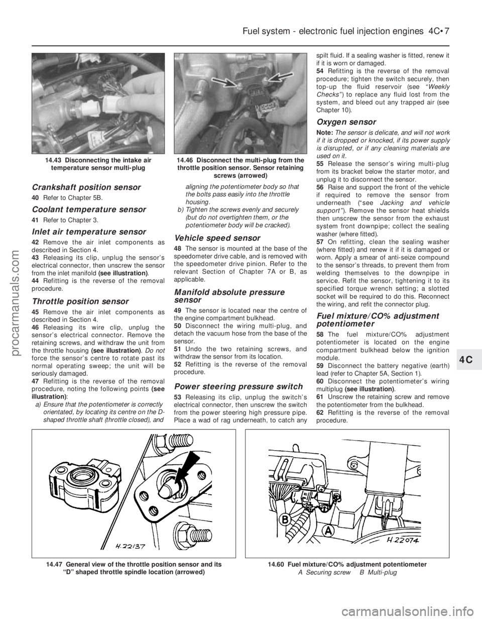
43 Releasing its clip, unplug the sensor’s
electrical connector, then unscrew the sensor
from the inlet manifold (see illustration).
44 Refitting is the reverse of the removal
procedure.
Throttle position sensor
45 Remove the air inlet components as
described in Section 4.
46 Releasing its wire clip, unplug the
sensor’s electrical connector. Remove the
retaining screws, and withdraw the unit from
the throttle housing (see illustration). Do not
force the sensor’s centre to rotate past its
normal operating sweep; the unit will be
seriously damaged.
47 Refitting is the reverse of the removal
procedure, noting the following points (see
illustration) :
a) Ensure that the potentiometer is correctly
orientated, by locating its centre on the D-
shaped throttle shaft (throttle closed), and aligning the potentiometer body so that
the bolts pass easily into the throttle
housing.
b) Tighten the screws evenly and securely
(but do not overtighten them, or the
potentiometer body will be cracked).
Vehicle speed sensor
48 The sensor is mounted at the base of the
speedometer drive cable, and is removed with
the speedometer drive pinion. Refer to the
relevant Section of Chapter 7A or B, as
applicable.
Manifold absolute pressure
sensor
49 The sensor is located near the centre of
the engine compartment bulkhead.
50 Disconnect the wiring multi-plug, and
detach the vacuum hose from the base of the
sensor.
51 Undo the two retaining screws, and
withdraw the sensor from its location.
52 Refitting is the reverse of the removal
procedure.
Power steering pressure switch
53 Releasing its clip, unplug the switch’s
electrical connector, then unscrew the switch
from the power steering high pressure pipe.
Place a wad of rag underneath, to catch any spilt fluid. If a sealing washer is fitted, renew it
if it is worn or damaged.
54
Refitting is the reverse of the removal
procedure; tighten the switch securely, then
top-up the fluid reservoir (see “Weekly
Checks” ) to replace any fluid lost from the
system, and bleed out any trapped air (see
Chapter 10).
Oxygen sensor
Note: The sensor is delicate, and will not work
if it is dropped or knocked, if its power supply
is disrupted, or if any cleaning materials are
used on it.
55 Release the sensor’s wiring multi-plug
from its bracket below the starter motor, and
unplug it to disconnect the sensor.
56 Raise and support the front of the vehicle
if required to remove the sensor from
underneath (“see Jacking and vehicle
support” ). Remove the sensor heat shields
then unscrew the sensor from the exhaust
system front downpipe; collect the sealing
washer (where fitted).
57 On refitting, clean the sealing washer
(where fitted) and renew it if it is damaged or
worn. Apply a smear of anti-seize compound
to the sensor’s threads, to prevent them from
welding themselves to the downpipe in
service. Refit the sensor, tightening it to its
specified torque wrench setting; a slotted
socket will be required to do this. Reconnect
the wiring, and refit the connector plug.
Fuel mixture/CO% adjustment
potentiometer
58 The fuel mixture/CO% adjustment
potentiometer is located on the engine
compartment bulkhead below the ignition
module.
59 Disconnect the battery negative (earth)
lead (refer to Chapter 5A, Section 1).
60 Disconnect the potentiometer’s wiring
multiplug (see illustration) .
61 Unscrew the retaining screw and remove
the potentiometer from the bulkhead.
62 Refitting is the reverse of the removal
procedure.
Fuel system - electronic fuel injection engines 4C•7
14.46 Disconnect the multi-plug from the throttle position sensor. Sensor retaining screws (arrowed)14.43 Disconnecting the intake airtemperature sensor multi-plug
14.60 Fuel mixture/CO% adjustment potentiometer
A Securing screw B Multi-plug14.47 General view of the throttle position sensor and its “D” shaped throttle spindle location (arrowed)
4C
1595Ford Fiesta Remakeprocarmanuals.com
http://vnx.su
Page 177 of 296
1 General information
The braking system is of the diagonally
split, dual-circuit hydraulic type, with servo
assistance to the front disc brakes and rear
drum brakes. The dual-circuit hydraulic
system is a safety feature - in the event of a
malfunction somewhere in one of the
hydraulic circuits, the other circuit continues
to operate, providing at least some braking
effort. Under normal circumstances, both
brake circuits operate in unison, to provide
efficient braking.
The master cylinder (and the vacuum servo
unit to which it is bolted) is located on the left-
hand side of the bulkhead in the engine
compartment. On all right-hand drive variants,
they are jointly operated via a transverse
cross-link from the brake pedal.
Brake pressure control valves are fitted in-
line to each rear brake circuit, their function
being to regulate the braking force available at
each rear wheel, reducing the possibility of
the rear wheels locking up under heavy
braking. Courier models also have a “light-
laden” valve incorporated into the rear braking
circuits for the same reason. The front brake discs are of the ventilated
type on XR2i and ABS-equipped models, with
solid discs fitted on all other models. The front
brake calipers are of single sliding piston type
mounted on the front spindle carriers each
side. Each rear brake shoe assembly is operated
by a twin-piston wheel cylinder. The leading
brake shoe in each brake unit has a thicker
lining than the trailing shoe, so that they wear
proportionally. To take up the brake
adjustment as the linings wear, each rear
brake assembly incorporates an automatic
adjuster mechanism. The cable-operated handbrake acts on
both rear brakes, to provide an independent
means of brake operation. An anti-lock braking system (ABS) is
available on some models, and has many of
the components in common with the conventional braking system. Further details
on ABS can be found later in this Chapter.
Note:
When servicing any part of the system,
work carefully and methodically; also observe
scrupulous cleanliness when overhauling any
part of the hydraulic system. Always renew
components (in axle sets, where applicable) if
in doubt about their condition, and use only
genuine Ford replacement parts, or at least
those of known good quality. Note the
warnings given in “Safety first” and at relevant
points in this Chapter concerning the dangers
of asbestos dust and hydraulic fluid.
2 Front brake pads - renewal
2
Warning: Disc brake pads MUST
be renewed on both front
wheels at the same time -
NEVER renew the pads on only
one wheel, as uneven braking may result.
The front brake calipers will be of Bendix
or Teves manufacture, and if they or their
component parts require renewal, ensure
that the correct type is fitted. Dust created
by wear of the pads may contain asbestos,
which is a health hazard. Never blow it out
with compressed air, and do not inhale any
of it. DO NOT use petroleum-based
solvents to clean brake parts - use brake
cleaner or methylated spirit only. DO NOT allow any brake fluid, oil or grease to
contact the brake pads or disc. Also refer
to the warning in Section 13 concerning
the dangers of hydraulic fluid.
1
Chock the rear wheels then jack up the
front of the car and support it on axle stands
(see “Jacking and Vehicle Support” ). Remove
the front roadwheels.
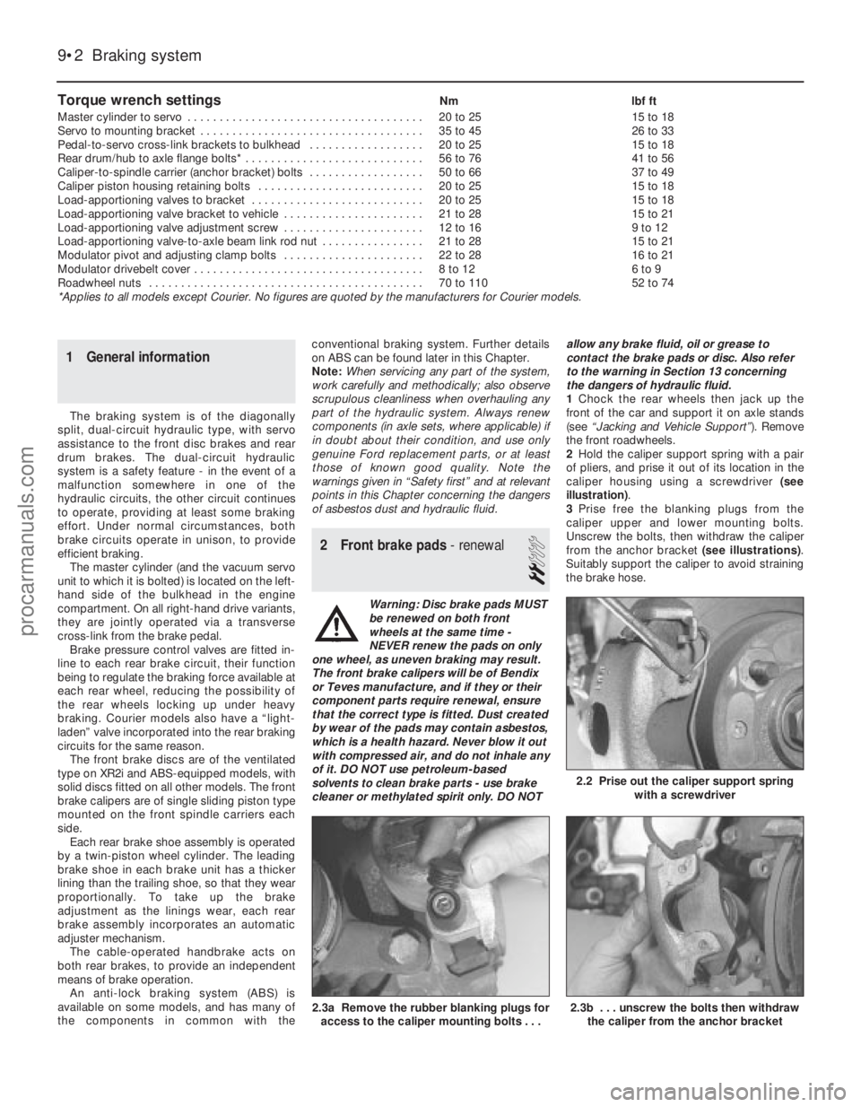
2 Hold the caliper support spring with a pair
of pliers, and prise it out of its location in the
caliper housing using a screwdriver (see
illustration) .
3 Prise free the blanking plugs from the
caliper upper and lower mounting bolts.
Unscrew the bolts, then withdraw the caliper
from the anchor bracket (see illustrations).
Suitably support the caliper to avoid straining
the brake hose.
Torque wrench settingsNm lbf ft
Master cylinder to servo . . . . . . . . . . . . . . . . . . . . . . . . . . . . . . . . . . . .\
. 20 to 25 15 to 18
Servo to mounting bracket . . . . . . . . . . . . . . . . . . . . . . . . . . . . . . . . . . . 35 to 45 26 to 33
Pedal-to-servo cross-link brackets to bulkhead . . . . . . . . . . . . . . . . . . 20 to 25 15 to 18
Rear drum/hub to axle flange bolts* . . . . . . . . . . . . . . . . . . . . . . . . . . . . 56 to 76 41 to 56
Caliper-to-spindle carrier (anchor bracket) bolts . . . . . . . . . . . . . . . . . . 50 to 66 37 to 49
Caliper piston housing retaining bolts . . . . . . . . . . . . . . . . . . . . . . . . . . 20 to 25 15 to 18
Load-apportioning valves to bracket . . . . . . . . . . . . . . . . . . . . . . . . . . . 20 to 25 15 to 18
Load-apportioning valve bracket to vehicle . . . . . . . . . . . . . . . . . . . . . . 21 to 28 15 to 21
Load-apportioning valve adjustment screw . . . . . . . . . . . . . . . . . . . . . . 12 to 16 9 to 12
Load-apportioning valve-to-axle beam link rod nut . . . . . . . . . . . . . . . . 21 to 28 15 to 21
Modulator pivot and adjusting clamp bolts . . . . . . . . . . . . . . . . . . . . . . 22 to 28 16 to 21
Modulator drivebelt cover . . . . . . . . . . . . . . . . . . . . . . . . . . . . . . . . . . . .\
8 to 12 6 to 9
Roadwheel nuts . . . . . . . . . . . . . . . . . . . . . . . . . . . . . . . . . . . .\
. . . . . . . 70 to 110 52 to 74
*Applies to all models except Courier. No figures are quoted by the manu\
facturers for Courier models.
9•2 Braking system
2.3b . . . unscrew the bolts then withdraw the caliper from the anchor bracket2.3a Remove the rubber blanking plugs foraccess to the caliper mounting bolts . . .
2.2 Prise out the caliper support spring with a screwdriver
1595Ford Fiesta Remakeprocarmanuals.com
http://vnx.su
Page 199 of 296
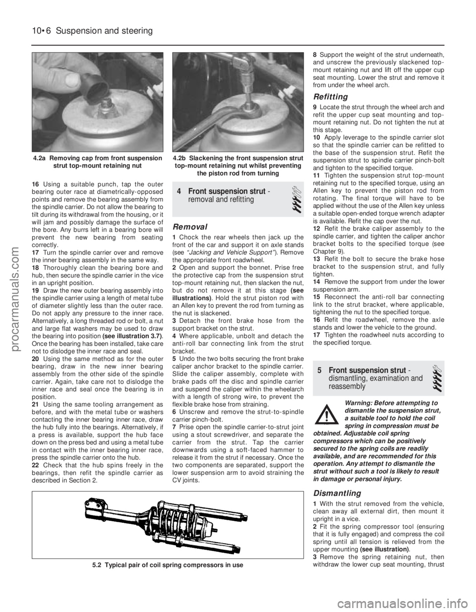
16Using a suitable punch, tap the outer
bearing outer race at diametrically-opposed
points and remove the bearing assembly from
the spindle carrier. Do not allow the bearing to
tilt during its withdrawal from the housing, or it
will jam and possibly damage the surface of
the bore. Any burrs left in a bearing bore will
prevent the new bearing from seating
correctly.
17 Turn the spindle carrier over and remove
the inner bearing assembly in the same way.
18 Thoroughly clean the bearing bore and
hub, then secure the spindle carrier in the vice
in an upright position.
19 Draw the new outer bearing assembly into
the spindle carrier using a length of metal tube
of diameter slightly less than the outer race.
Do not apply any pressure to the inner race.
Alternatively, a long threaded rod or bolt, a nut
and large flat washers may be used to draw
the bearing into position (see illustration 3.7).
Once the bearing has been installed, take care
not to dislodge the inner race and seal.
20 Using the same method as for the outer
bearing, draw in the new inner bearing
assembly from the other side of the spindle
carrier. Again, take care not to dislodge the
inner race and seal once the bearing is in
position.
21 Using the same tooling arrangement as
before, and with the metal tube or washers
contacting the inner bearing inner race, draw
the hub fully into the bearings. Alternatively, if
a press is available, support the hub face
down on the press bed and using a metal tube
in contact with the inner bearing inner race,
press the spindle carrier onto the hub.
22 Check that the hub spins freely in the
bearings, then refit the spindle carrier as
described in Section 2.4 Front suspension strut -
removal and refitting
3
Removal
1 Chock the rear wheels then jack up the
front of the car and support it on axle stands
(see “Jacking and Vehicle Support” ). Remove
the appropriate front roadwheel.
2 Open and support the bonnet. Prise free
the protective cap from the suspension strut
top-mount retaining nut, then slacken the nut,
but do not remove it at this stage (see
illustrations) . Hold the strut piston rod with
an Allen key to prevent the rod from turning as
the nut is slackened.
3 Detach the front brake hose from the
support bracket on the strut.
4 Where applicable, unbolt and detach the
anti-roll bar connecting link from the strut
bracket.
5 Undo the two bolts securing the front brake
caliper anchor bracket to the spindle carrier.
Slide the caliper assembly, complete with
brake pads off the disc and spindle carrier
and suspend the caliper within the wheelarch
with a length of strong wire, to prevent the
flexible brake hose from straining.
6 Unscrew and remove the strut-to-spindle
carrier pinch-bolt.
7 Prise open the spindle carrier-to-strut joint
using a stout screwdriver, and separate the
carrier from the strut. Tap the carrier
downwards using a soft-faced hammer to
release it from the strut if necessary. Once the
two components are separated, support the
lower suspension arm to avoid straining the
CV joints. 8
Support the weight of the strut underneath,
and unscrew the previously slackened top-
mount retaining nut and lift off the upper cup
seat mounting. Lower the strut and remove it
from under the wheel arch.
Refitting
9 Locate the strut through the wheel arch and
refit the upper cup seat mounting and top-
mount retaining nut. Do not tighten the nut at
this stage.
10 Apply leverage to the spindle carrier slot
so that the spindle carrier can be refitted to
the base of the suspension strut. Refit the
suspension strut to spindle carrier pinch-bolt
and tighten to the specified torque.
11 Tighten the suspension strut top-mount
retaining nut to the specified torque, using an
Allen key to prevent the piston rod from
rotating. The final torque will have to be
applied without the use of the Allen key unless
a suitable open-ended torque wrench adapter
is available. Refit the cap over the nut.
12 Refit the brake caliper assembly to the
spindle carrier, and tighten the caliper anchor
bracket bolts to the specified torque (see
Chapter 9).
13 Refit the bolt to secure the brake hose
bracket to the suspension strut, and fully
tighten.
14 Remove the support from under the lower
suspension arm.
15 Reconnect the anti-roll bar connecting
link to the strut bracket, where applicable,
tightening the nut to the specified torque.
16 Refit the roadwheel, remove the axle
stands and lower the vehicle to the ground.
17 Tighten the roadwheel nuts according to
the specified torque.
5 Front suspension strut -
dismantling, examination and
reassembly
4
Warning: Before attempting to
dismantle the suspension strut,
a suitable tool to hold the coil
spring in compression must be
obtained. Adjustable coil spring
compressors which can be positively
secured to the spring coils are readily
available, and are recommended for this
operation. Any attempt to dismantle the
strut without such a tool is likely to result
in damage or personal injury.
Dismantling
1 With the strut removed from the vehicle,
clean away all external dirt, then mount it
upright in a vice.
2 Fit the spring compressor tool (ensuring
that it is fully engaged) and compress the coil
spring until all tension is relieved from the
upper mounting (see illustration) .
3 Remove the spring retaining nut, then
withdraw the lower cup seat mounting, thrust
10•6 Suspension and steering
5.2 Typical pair of coil spring compressors in use
4.2b Slackening the front suspension strut
top-mount retaining nut whilst preventing the piston rod from turning4.2a Removing cap from front suspensionstrut top-mount retaining nut
1595Ford Fiesta Remakeprocarmanuals.com
http://vnx.su
Page 202 of 296
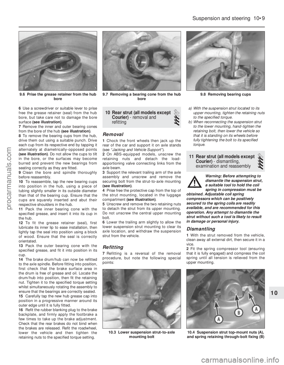
6Use a screwdriver or suitable lever to prise
free the grease retainer (seal) from the hub
bore, but take care not to damage the bore
surface (see illustration) .
7 Remove the inner and outer bearing cones
from the bore of the hub (see illustration).
8 To remove the bearing cups from the hub,
drive them out using a suitable punch. Drive
each cup from its respective end by tapping it
alternately at diametrically-opposed points
(see illustration) . Do not allow the cups to tilt
in the bore, or the surfaces may become
burred and prevent the new bearings from
seating correctly as they are fitted.
9 Clean the bore and spindle thoroughly
before reassembly.
10 To reassemble, tap the new bearing cups
into position in the hub, using a piece of
tubing slightly smaller in its outside diameter
than that of the bearing cup. Ensure that the
cups are squarely inserted and abut their
respective shoulders in the hub.
11 Pack the inner bearing cone with the
specified grease, and insert it into its cup in
the hub.
12 To fit the grease retainer (seal), first
lubricate its inner lip to ease installation, then
lightly tap the seal into position using a block
of wood. Ensure that the seal is correctly
orientated.
13 Pack the outer bearing cone with the
specified grease, and fit it into position in its
cup.
14 The brake drum/hub can now be refitted
to the axle spindle. Before fitting into position,
first check that the brake surface area in
the drum is free of grease and oil. Locate the
drum/hub into position, then fit the retaining
nut. Tighten it to the specified torque setting
whilst simultaneously rotating the assembly to
ensure that the bearings are correctly seated.
15 Carefully tap the new hub grease cap into
position in a progressive manner around its
outer edge until it is fully fitted.
16 Refit the rubber blanking plug to the brake
backplate, and firmly apply the footbrake a
few times to take up the brake adjustment.
Check that the rear brakes do not bind when
the brakes are released. Refit the roadwheel,
lower the vehicle and then tighten the
retaining nuts to the specified torque setting.10 Rear strut (all models except Courier) - removal and
refitting
3
Removal
1 Chock the front wheels then jack up the
rear of the car and support it on axle stands
(see “Jacking and Vehicle Support” ).
2 On ABS-equipped models, unscrew the
retaining nuts and detach the load-
apportioning valve connecting links from the
axle beam.
3 Support the relevant trailing arm of the axle
assembly and unscrew and remove the
securing bolt from the strut-to-axle mounting
(see illustration) .
4 Prise free the protective cap from the top of
the strut mounting, located in the luggage
compartment (see illustration) .
5 Unscrew and remove the two retaining nuts
to detach the strut from its upper mounting.
Do not unscrew the central upper mounting
bolt.
6 Lower the trailing arm slightly to allow the
lower suspension strut mounting to clear its
axle location, and withdraw the suspension
strut from the vehicle.
Refitting
7 Refitting is a reversal of the removal
procedure, but note the following special
points: a)
With the suspension strut located to its
upper mounting, tighten the retaining nuts
to the specified torque.
b) When reconnecting the suspension strut
to the lower mounting, hand-tighten the
retaining bolt, then lower the vehicle so
that it is standing on its wheels before
fully tightening the bolt to its specified
torque.
11 Rear strut (all models except
Courier) - dismantling,
examination and reassembly
4
Warning: Before attempting to
dismantle the suspension strut,
a suitable tool to hold the coil
spring in compression must be
obtained. Adjustable coil spring
compressors which can be positively
secured to the spring coils are readily
available, and are recommended for this
operation. Any attempt to dismantle the
strut without such a tool is likely to result
in damage or personal injury.
Dismantling
1 With the strut removed from the vehicle,
clean away all external dirt, then secure it in a
vice.
2 Fit the spring compressor tool (ensuring
that it is fully engaged) and compress the coil
spring until all tension is relieved from the
upper mounting.
Suspension and steering 10•9
9.8 Removing bearing cups9.7 Removing a bearing cone from the hub bore9.6 Prise the grease retainer from the hubbore
10.4 Suspension strut top-mount nuts (A),
and spring retaining through-bolt fixing (B)10.3 Lower suspension strut-to-axle mounting bolt
10
1595Ford Fiesta Remakeprocarmanuals.com
http://vnx.su
Page 203 of 296
3Unscrew and remove the upper mounting
through-bolt and nut.
4 Withdraw the upper mounting cup and the
spring seat.
5 The suspension strut and coil spring can now
be separated. If the coil spring or strut is to be
renewed, the original coil spring must be
released from the compressor. If it is to be re-
used, the coil spring can be left in compression.
Examination
6 With the strut assembly now completely
dismantled, examine the mounting
components for wear, damage or deformation.
Renew any of the components as necessary.
7 Examine the strut for signs of fluid leakage.
Check the strut piston for signs of pitting
along its entire length, and check the strut
body for signs of damage or deterioration of
the mountings. Test the operation of the strut,
holding it in an upright position, by moving the
piston through a full stroke, and then through
short strokes of 50 to 100 mm. In both cases,
the resistance felt should be smooth and
continuous. If the resistance is jerky, or
uneven, or if there is any visible sign of wear
or damage to the strut, renewal is necessary.
Reassembly
8 Reassembly is a reversal of the dismantling
procedure but note the following points: a) When the spring is located over the
suspension strut, the spring seat, cup and
through-bolt fitted, tighten the retaining
bolt to the specified torque.
b) When reassembled, check that the upper
and lower spring tails are correctly
engaged with their spring seats before
removing the spring compressor.
12 Rear axle (all models except
Courier) -
removal and refitting
3
Removal
1 Chock the front wheels then jack up the
rear of the car and support it on axle stands
(see “Jacking and Vehicle Support” ). Remove
the rear roadwheels.
2 Refer to Chapter 9 for details, and disconnect
the handbrake cable equaliser from the primary
cable. Remove the handbrake rear cable from
its adjuster and its fixed body locations.
3 Disconnect the rear brake flexible hydraulic
brake hoses from their rigid line connections.
Clamp the hoses before disconnecting them,
to minimise the fluid loss and air entry into the
hydraulic system (see Chapter 9 for details).
4 On ABS-equipped models, undo the
retaining nuts and detach the ABS load-
apportioning valve operating links from the
axle beam. Do not remove the load-
apportioning valve (see Chapter 9).
5 Locate suitable jacks or axle stands under
the axle beam to support its weight (not to lift
it), then unscrew the four mounting bracket
bolts each side. 6
Unscrew and remove the strut-to-axle
mounting bolt each side.
7 Check that all associated fittings are clear,
then lower the axle and remove it from under
the vehicle.
8 If the twist beam axle has been damaged, it
must be renewed. Refer to Chapter 9 for
details on removing the rear brakes from the
axle. To remove the front mounting/pivot
brackets from the axle, unscrew the pivot bolt.
Refitting
9 Refitting is a reversal of the removal
procedure, but note the following: a) Reconnect the axle at the front floor mountings first, and tighten the retaining
bolts to the specified torque.
b) Reconnect the axle to the suspension struts, but do not fully retighten the securing
bolts until after the vehicle is lowered to the
ground and is standing on its wheels.
c) Ensure that all brake fluid line connections are clean before reconnecting them. Refer
to the appropriate Sections in Chapter 9
for specific details on reconnecting the
brake lines, bleeding the brake hydraulic
system, and for reconnecting the
handbrake cable and its adjustment.
d) When the vehicle is lowered and is standing
on its wheels, tighten the suspension
fastenings to their specified torque settings.
13 Rear axle pivot bushes (all
models except Courier) -
renewal
3
Note: Two different types of pivot bushes
have been fitted during the course of Fiesta
production. It is understood that once stocks
of the early type are exhausted, only the latter
type will be supplied by Ford parts dealers. If
renewing pivot bushes on a pre-April 1990
model, and only the later type bushes are
available, fit the new bushes as described
from paragraph 15 onward.
Pre-April 1990 models
1 Chock the front wheels then jack up the
rear of the car and support it on axle stands
(see “Jacking and Vehicle Support” ).2
Position a suitable support (preferably
adjustable) under the axle twist beam so that
it is capable of carrying the weight of the axle
(not the weight of the vehicle).
3 On ABS-equipped models, undo the
retaining nuts and detach the ABS load-
apportioning valve operating links from the
axle beam. Do not remove the load-
apportioning valve (see Chapter 9).
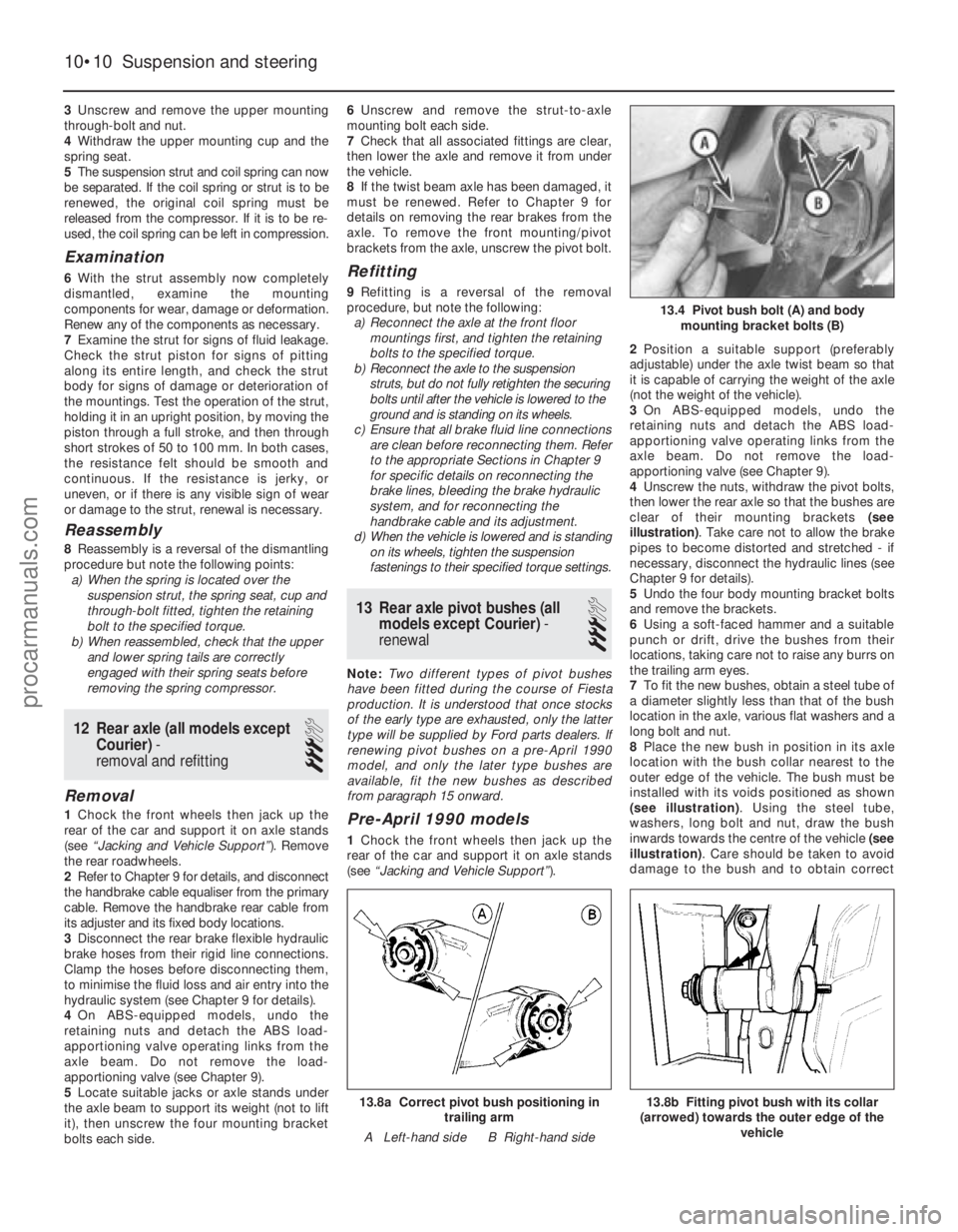
4 Unscrew the nuts, withdraw the pivot bolts,
then lower the rear axle so that the bushes are
clear of their mounting brackets (see
illustration) . Take care not to allow the brake
pipes to become distorted and stretched - if
necessary, disconnect the hydraulic lines (see
Chapter 9 for details).
5 Undo the four body mounting bracket bolts
and remove the brackets.
6 Using a soft-faced hammer and a suitable
punch or drift, drive the bushes from their
locations, taking care not to raise any burrs on
the trailing arm eyes.
7 To fit the new bushes, obtain a steel tube of
a diameter slightly less than that of the bush
location in the axle, various flat washers and a
long bolt and nut.
8 Place the new bush in position in its axle
location with the bush collar nearest to the
outer edge of the vehicle. The bush must be
installed with its voids positioned as shown
(see illustration) . Using the steel tube,
washers, long bolt and nut, draw the bush
inwards towards the centre of the vehicle (see
illustration) . Care should be taken to avoid
damage to the bush and to obtain correct
10•10 Suspension and steering
13.8b Fitting pivot bush with its collar
(arrowed) towards the outer edge of the vehicle13.8a Correct pivot bush positioning intrailing arm
A Left-hand side B Right-hand side
13.4 Pivot bush bolt (A) and body mounting bracket bolts (B)
1595Ford Fiesta Remakeprocarmanuals.com
http://vnx.su
Page 210 of 296
Refitting
All models
38Refitting is a reversal of removal, bearing
in mind the following points:
a) Tighten all nuts and bolts to the specified torque. Remove the plugs from the
disconnected pipes, hoses and unions
and ensure that the pipes are located
correctly so that they do not foul any
surrounding components.
b) Refit the auxiliary drivebelt as described in
Chapter 1.
c) Where drained, refill the cooling system as described in Chapter 1.
d) Refit or reconnect any additional
components removed for access as
described in the relevant Sections and
Chapters of this manual.
e) On completion, bleed the power steering
hydraulic system as described in Section
27. Check for any signs of fluid leakage
from the system hoses and connections.
26 Power steering fluid cooler -
removal and refitting
2
Removal
1 Disconnect the battery negative (earth) lead
(refer to Chapter 5A, Section 1).
2 Position a suitable container beneath the
power steering fluid cooler hose connections,
then disconnect the hoses at the quick-fit
couplings on the fluid cooler. Allow the fluid to
drain from the hose and reservoir into the
container.
3 Plug the exposed ends of the hose and the
reservoir, to prevent the ingress of dirt and
excessive fluid loss.
4 Refer to Chapter 11 and remove the bonnet
lock assembly and the front bumper.
5 Undo the bolts securing the cooler side
support bracket and the bonnet lock stay, and
remove the fluid cooler and bonnet lock stay
as an assembly.
6 Undo the two bolts and remove the stay
from the fluid cooler.
Refitting
7 Refitting is a reversal of removal. On
completion, bleed the power steering
hydraulic system as described in Section 27.
27 Power steering hydraulic system - bleeding
2
1Following any operation in which the power
steering fluid lines have been disconnected,
the power steering system must be bled to
remove any trapped air.
2 With the front wheel in the straight-ahead
position, check the power steering fluid level
in the reservoir and, if low, top-up with fresh fluid to the “MAX” or “MAX COLD” level mark.
Pour the fluid slowly to prevent air bubbles
forming, and use only the specified fluid (refer
to
“Lubricants, fluids and tyre pressures” ).
3 Start the engine and allow it to idle. Check
the hoses and connections for leaks.
4 Stop the engine and recheck the fluid level.
Add more, if necessary, up to the “MAX” or
“MAX COLD” level mark.
5 Start the engine again, allow it to idle, then
bleed the system by slowly moving the
steering from lock-to-lock several times. This
should purge the system of all internal air.
However, if air remains in the system
(indicated by the steering operation being very
noisy), leave the vehicle overnight and repeat
the procedure again the next day.
6 If air still remains in the system, it may be
necessary to resort to the Ford method of
bleeding, which uses a vacuum pump and a
modified reservoir filler cap to which the pump
can be connected. Turn the steering to the
right until it is near the stop, then fit the
vacuum pump to the fluid reservoir, and apply
0.51 bars of vacuum. Maintain the vacuum for
a minimum of 5 minutes, then repeat
the procedure with the steering turned to the
left.
7 Keep the fluid level topped-up throughout
the bleeding procedure; note that the fluid
temperature increases, the level will rise.
8 On completion, switch the engine off, and
return the wheels to the straight-ahead
position.
28 Track rod end balljoint -
removal and refitting
2
Removal
1 Chock the rear wheels then jack up the
front of the car and support it on axle stands
(see “Jacking and Vehicle Support” ). Remove
the appropriate front roadwheel.
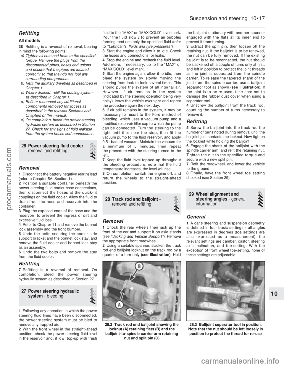
2 Using a suitable spanner, slacken the track
rod end balljoint locknut on the track rod by a
quarter of a turn only (see illustration). Holdthe balljoint stationary with another spanner
engaged with the flats at its inner end to
prevent it from turning.
3
Extract the split pin, then loosen off the
retaining nut. If the balljoint is to be renewed,
the nut can be fully removed. If the existing
balljoint is to be reconnected, the nut should
be slackened off a couple of turns only at first,
and left in position to protect the joint threads
as the joint is separated from the spindle
carrier. To release the tapered shank of the
joint from the spindle carrier, use a balljoint
separator tool as shown (see illustration). If
the joint is to be re-used, take care not to
damage the rubber dust cover when using a
separator tool.
4 Unscrew the balljoint from the track rod,
counting the number of turns necessary to
remove it.
Refitting
5 Screw the balljoint into the track rod the
number of turns noted during removal until the
balljoint just contacts the locknut. Now tighten
the locknut while holding the balljoint.
6 Engage the shank of the balljoint with the
spindle carrier arm, and refit the retaining nut.
Tighten the nut to the specified torque and
secure with a new split pin.
7 Refit the roadwheel, and lower the vehicle
to the ground.
8 Finally, have the front wheel toe setting
checked (see Section 29).
29 Wheel alignment and steering angles - general
information
4
General
1 A car’s steering and suspension geometry
is defined in four basic settings - all angles
are expressed in degrees (toe settings are
also expressed as a measurement); the
relevant settings are camber, castor, steering
axis inclination, and toe-setting. With the
exception of front wheel toe-setting, none of
these settings are adjustable.
Suspension and steering 10•17
28.3 Balljoint separator tool in position.
Note that the nut should be left loosely in position to protect the thread for re-use28.2 Track rod end balljoint showing the locknut (A) retaining flats (B) and the
balljoint-to-spindle carrier arm retaining
nut and split pin (C)
10
1595Ford Fiesta Remakeprocarmanuals.com
http://vnx.su
Page 271 of 296
1595 Ford Fiesta Remake
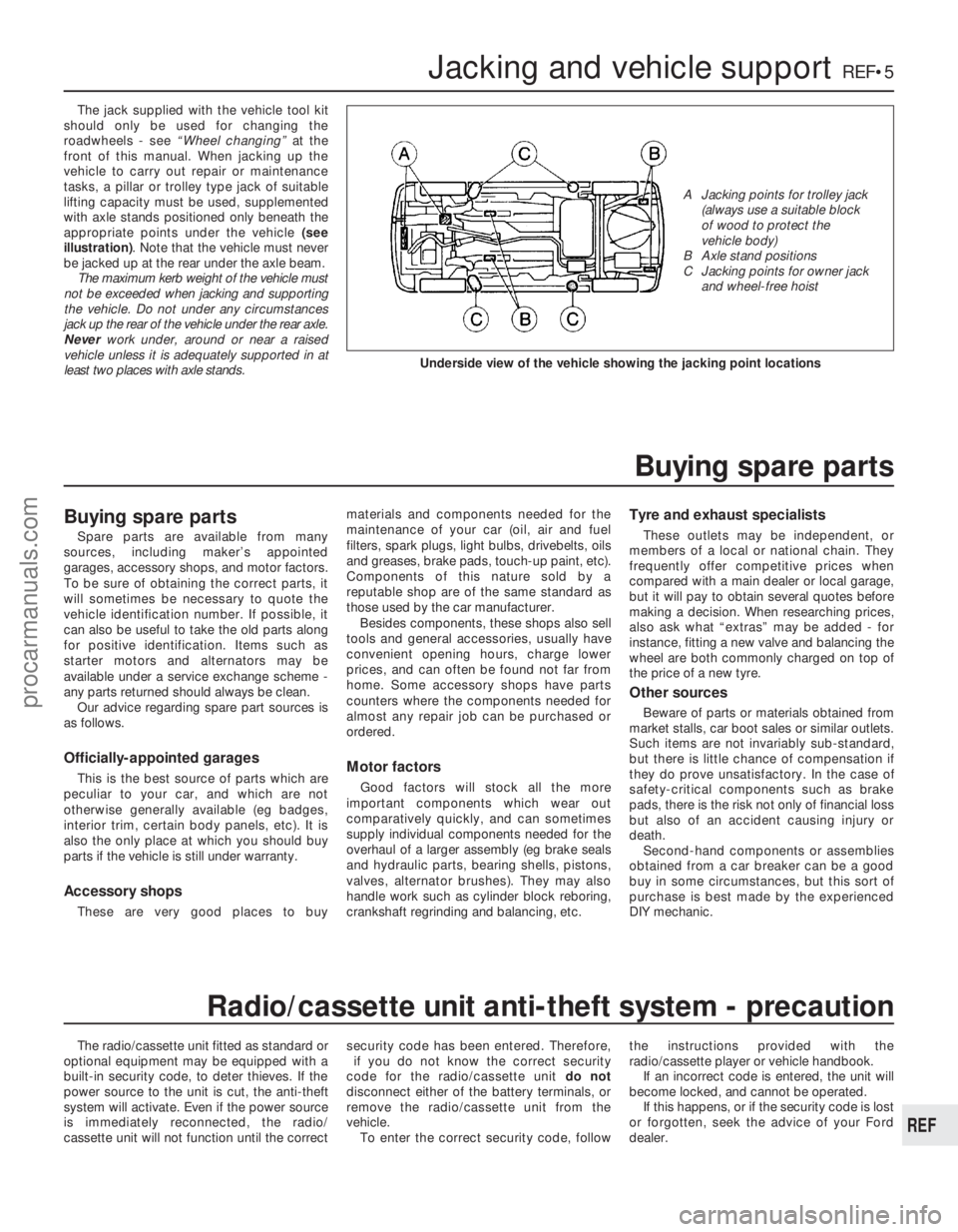
The jack supplied with the vehicle tool kit
should only be used for changing the
roadwheels - see “Wheel changing” at the
front of this manual. When jacking up the
vehicle to carry out repair or maintenance
tasks, a pillar or trolley type jack of suitable
lifting capacity must be used, supplemented
with axle stands positioned only beneath the
appropriate points under the vehicle (see
illustration) . Note that the vehicle must never
be jacked up at the rear under the axle beam. The maximum kerb weight of the vehicle must
not be exceeded when jacking and supporting
the vehicle. Do not under any circumstances
jack up the rear of the vehicle under the rear axle.
Never work under, around or near a raised
vehicle unless it is adequately supported in at
least two places with axle stands.
The radio/cassette unit fitted as standard or
optional equipment may be equipped with a
built-in security code, to deter thieves. If the
power source to the unit is cut, the anti-theft
system will activate. Even if the power source
is immediately reconnected, the radio/
cassette unit will not function until the correct security code has been entered. Therefore,
if you do not know the correct security
code for the radio/cassette unit do not
disconnect either of the battery terminals, or
remove the radio/cassette unit from the
vehicle. To enter the correct security code, follow the instructions provided with the
radio/cassette player or vehicle handbook.
If an incorrect code is entered, the unit will
become locked, and cannot be operated.
If this happens, or if the security code is lost
or forgotten, seek the advice of your Ford
dealer.
Jacking and vehicle supportREF•5
REF
Radio/cassette unit anti-theft system - precaution
Underside view of the vehicle showing the jacking point locations
A Jacking points for trolley jack (always use a suitable block
of wood to protect the
vehicle body)
B Axle stand positions
C Jacking points for owner jack and wheel-free hoist
Buying spare parts
Spare parts are available from many
sources, including maker’s appointed
garages, accessory shops, and motor factors.
To be sure of obtaining the correct parts, it
will sometimes be necessary to quote the
vehicle identification number. If possible, it
can also be useful to take the old parts along
for positive identification. Items such as
starter motors and alternators may be
available under a service exchange scheme -
any parts returned should always be clean.
Our advice regarding spare part sources is
as follows.
Officially-appointed garages
This is the best source of parts which are
peculiar to your car, and which are not
otherwise generally available (eg badges,
interior trim, certain body panels, etc). It is
also the only place at which you should buy
parts if the vehicle is still under warranty.
Accessory shops
These are very good places to buy materials and components needed for the
maintenance of your car (oil, air and fuel
filters, spark plugs, light bulbs, drivebelts, oils
and greases, brake pads, touch-up paint, etc).
Components of this nature sold by a
reputable shop are of the same standard as
those used by the car manufacturer.
Besides components, these shops also sell
tools and general accessories, usually have
convenient opening hours, charge lower
prices, and can often be found not far from
home. Some accessory shops have parts
counters where the components needed for
almost any repair job can be purchased or
ordered.
Motor factors
Good factors will stock all the more
important components which wear out
comparatively quickly, and can sometimes
supply individual components needed for the
overhaul of a larger assembly (eg brake seals
and hydraulic parts, bearing shells, pistons,
valves, alternator brushes). They may also
handle work such as cylinder block reboring,
crankshaft regrinding and balancing, etc.
Tyre and exhaust specialists
These outlets may be independent, or
members of a local or national chain. They
frequently offer competitive prices when
compared with a main dealer or local garage,
but it will pay to obtain several quotes before
making a decision. When researching prices,
also ask what “extras” may be added - for
instance, fitting a new valve and balancing the
wheel are both commonly charged on top of
the price of a new tyre.
Other sources
Beware of parts or materials obtained from
market stalls, car boot sales or similar outlets.
Such items are not invariably sub-standard,
but there is little chance of compensation if
they do prove unsatisfactory. In the case of
safety-critical components such as brake
pads, there is the risk not only of financial loss
but also of an accident causing injury or
death. Second-hand components or assemblies
obtained from a car breaker can be a good
buy in some circumstances, but this sort of
purchase is best made by the experienced
DIY mechanic.
Buying spare parts
procarmanuals.com
http://vnx.su