window FORD FIESTA 1989 Service Repair Manual
[x] Cancel search | Manufacturer: FORD, Model Year: 1989, Model line: FIESTA, Model: FORD FIESTA 1989Pages: 296, PDF Size: 10.65 MB
Page 4 of 296

All other engi")
Ignition system
Firing order:HCS engines . . . . . . . . . . . . . . . . . . . . . . . . . . . . . . . . . . . .\
. . . . . . . . 1-2-4-3 (No 1 cylinder at timing chain end of engine)
All other engines . . . . . . . . . . . . . . . . . . . . . . . . . . . . . . . . . . . .\
. . . . . 1-3-4-2 (No 1 cylinder at timing belt end of engine)
Spark plugs*:
HCS engines . . . . . . . . . . . . . . . . . . . . . . . . . . . . . . . . . . . .\
. . . . . . . . Champion RS9YCC or RS9YC
1.4 and 1.6 litre CVH (carburettor) engines . . . . . . . . . . . . . . . . . . . . Champion RC7YCC or RC7YC
1.6 litre CVH (EFi fuel injection) and PTE engines Non-turbo models . . . . . . . . . . . . . . . . . . . . . . . . . . . . . . . . . . . .\
. . Champion RC7YCC4 or RC7YC4
Turbo models . . . . . . . . . . . . . . . . . . . . . . . . . . . . . . . . . . . .\
. . . . . Champion C61YC
1.6 and 1.8 litre Zetec engines . . . . . . . . . . . . . . . . . . . . . . . . . . . . . . Champion RE7YCC
Electrode gap*:
HCS engines . . . . . . . . . . . . . . . . . . . . . . . . . . . . . . . . . . . .\
. . . . . . . . 1.0 mm
1.4 litre CVH (carburettor) engines . . . . . . . . . . . . . . . . . . . . . . . . . . . 0.8 mm
1.4 litre CVH (CFi fuel injection) and PTE engine . . . . . . . . . . . . . . . . 1.0 mm
1.6 litre CVH (carburettor) engines: With Champion RC7YCC . . . . . . . . . . . . . . . . . . . . . . . . . . . . . . . . 0.8 mmWith Champion RC7YC . . . . . . . . . . . . . . . . . . . . . . . . . . . . . . . . . 0.7 mm
1.6 litre CVH (EFi fuel injection) engines: Non-turbo models . . . . . . . . . . . . . . . . . . . . . . . . . . . . . . . . . . . .\
. . 1.0 mm
Turbo models . . . . . . . . . . . . . . . . . . . . . . . . . . . . . . . . . . . .\
. . . . . 0.7 mm
1.6 and 1.8 litre Zetec engines . . . . . . . . . . . . . . . . . . . . . . . . . . . . . . 1.3 mm
Spark plug (HT) leads: HCS engines . . . . . . . . . . . . . . . . . . . . . . . . . . . . . . . . . . . .\
. . . . . . . . Champion LS-28
1.4 and 1.6 litre CVH (carburettor) engines . . . . . . . . . . . . . . . . . . . . Champion LS-14
1.4 litre CVH (CFi fuel injection) and PTE engines . . . . . . . . . . . . . . . Champion LS-14
1.6 litre CVH (EFi fuel injection) engines . . . . . . . . . . . . . . . . . . . . . . . Champion LS-26
1.6 and 1.8 litre Zetec engines . . . . . . . . . . . . . . . . . . . . . . . . . . . . . . Champion type not available
Maximum resistance per lead . . . . . . . . . . . . . . . . . . . . . . . . . . . . . . . . 30 000 ohms * Information on spark plug types and electrode gaps is as recommended b\
y Champion Spark Plug. Where alternative types are used, refer to their
manufacturer’s recommendations.
Braking system
Minimum front brake pad lining thickness . . . . . . . . . . . . . . . . . . . . . . . 1.5 mm
Minimum rear brake shoe lining thickness . . . . . . . . . . . . . . . . . . . . . . . 1.0 mm
Tyres
Tyre pressures . . . . . . . . . . . . . . . . . . . . . . . . . . . . . . . . . . . .\
. . . . . . . . See “Weekly Checks”
Wiper blades
Windscreen . . . . . . . . . . . . . . . . . . . . . . . . . . . . . . . . . . . .\
. . . . . . . . . . . Champion X-4803Tailgate/rear window . . . . . . . . . . . . . . . . . . . . . . . . . . . . . . . . . . . .\
. . . Champion X-4103
Torque wrench settingsNm lbf ft
Auxiliary drivebelt cover fasteners . . . . . . . . . . . . . . . . . . . . . . . . . . . . . 8 6
Auxiliary drivebelt adjustment: Adjusting bolt (sliding arm) . . . . . . . . . . . . . . . . . . . . . . . . . . . . . . . . . 2216
Central (locking) bolt . . . . . . . . . . . . . . . . . . . . . . . . . . . . . . . . . . . .\
. . 2216
Pinion (adjuster) nut . . . . . . . . . . . . . . . . . . . . . . . . . . . . . . . . . . . .\
. . 129
Alternator mounting bolts . . . . . . . . . . . . . . . . . . . . . . . . . . . . . . . . . . 2418
Tensioner pulley centre bolt (HCS engines) . . . . . . . . . . . . . . . . . . . . 2015
Engine oil drain plug . . . . . . . . . . . . . . . . . . . . . . . . . . . . . . . . . . . .\
. . . . 2418
Manual transmission filler/level plug . . . . . . . . . . . . . . . . . . . . . . . . . . . . 2015
Spark plugs: HCS engines . . . . . . . . . . . . . . . . . . . . . . . . . . . . . . . . . . . .\
. . . . . . . . 1813
CVH and PTE engines . . . . . . . . . . . . . . . . . . . . . . . . . . . . . . . . . . . .\
2418
Zetec engines . . . . . . . . . . . . . . . . . . . . . . . . . . . . . . . . . . . .\
. . . . . . . 1511
Roadwheel nuts . . . . . . . . . . . . . . . . . . . . . . . . . . . . . . . . . . . .\
. . . . . . . 71 to 100 52 to 74
Servicing Specifications1•3
1
1595Ford Fiesta Remakeprocarmanuals.com
http://vnx.su
Page 18 of 296
point at the engine to the end of the tailpipe.
Ideally, this should be done on a hoist, where
unrestricted access is available; if a hoist is
not available, raise and support the vehicle on
axle stands.
2Check the pipes and connections for
evidence of leaks, severe corrosion, or
damage. Make sure that all brackets and
rubber mountings are in good condition, and
tight; if any of the mountings are to be
renewed, ensure that the replacements are of
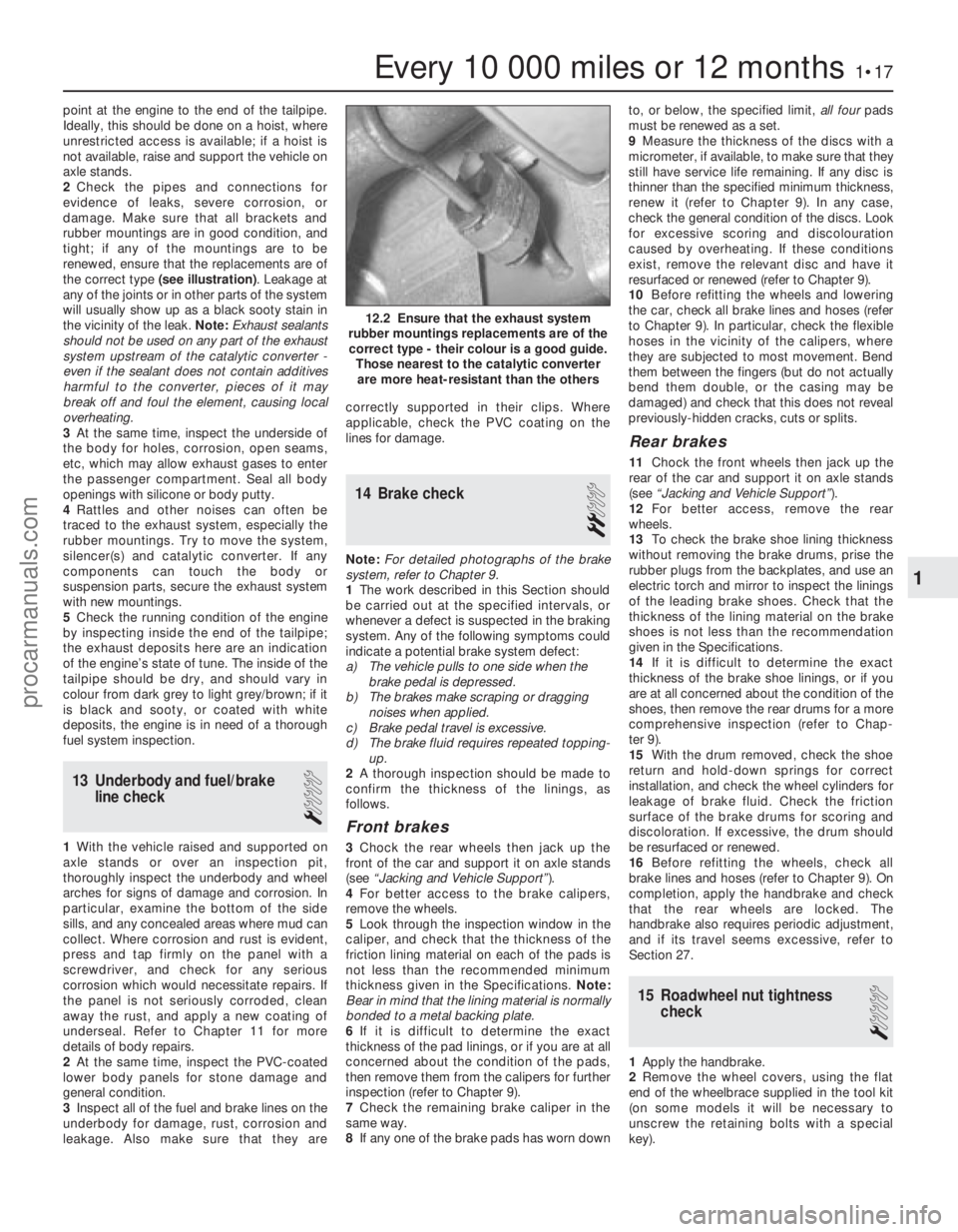
the correct type (see illustration) . Leakage at
any of the joints or in other parts of the system
will usually show up as a black sooty stain in
the vicinity of the leak. Note: Exhaust sealants
should not be used on any part of the exhaust
system upstream of the catalytic converter -
even if the sealant does not contain additives
harmful to the converter, pieces of it may
break off and foul the element, causing local
overheating.
3 At the same time, inspect the underside of
the body for holes, corrosion, open seams,
etc, which may allow exhaust gases to enter
the passenger compartment. Seal all body
openings with silicone or body putty.
4 Rattles and other noises can often be
traced to the exhaust system, especially the
rubber mountings. Try to move the system,
silencer(s) and catalytic converter. If any
components can touch the body or
suspension parts, secure the exhaust system
with new mountings.
5 Check the running condition of the engine
by inspecting inside the end of the tailpipe;
the exhaust deposits here are an indication
of the engine’s state of tune. The inside of the
tailpipe should be dry, and should vary in
colour from dark grey to light grey/brown; if it
is black and sooty, or coated with white
deposits, the engine is in need of a thorough
fuel system inspection.
13 Underbody and fuel/brake line check
1
1With the vehicle raised and supported on
axle stands or over an inspection pit,
thoroughly inspect the underbody and wheel
arches for signs of damage and corrosion. In
particular, examine the bottom of the side
sills, and any concealed areas where mud can
collect. Where corrosion and rust is evident,
press and tap firmly on the panel with a
screwdriver, and check for any serious
corrosion which would necessitate repairs. If
the panel is not seriously corroded, clean
away the rust, and apply a new coating of
underseal. Refer to Chapter 11 for more
details of body repairs.
2 At the same time, inspect the PVC-coated
lower body panels for stone damage and
general condition.
3 Inspect all of the fuel and brake lines on the
underbody for damage, rust, corrosion and
leakage. Also make sure that they are correctly supported in their clips. Where
applicable, check the PVC coating on the
lines for damage.
14 Brake check
2
Note:
For detailed photographs of the brake
system, refer to Chapter 9.
1 The work described in this Section should
be carried out at the specified intervals, or
whenever a defect is suspected in the braking
system. Any of the following symptoms could
indicate a potential brake system defect:
a) The vehicle pulls to one side when the brake pedal is depressed.
b) The brakes make scraping or dragging
noises when applied.
c) Brake pedal travel is excessive.
d) The brake fluid requires repeated topping-
up.
2 A thorough inspection should be made to
confirm the thickness of the linings, as
follows.
Front brakes
3 Chock the rear wheels then jack up the
front of the car and support it on axle stands
(see “Jacking and Vehicle Support” ).
4 For better access to the brake calipers,
remove the wheels.
5 Look through the inspection window in the
caliper, and check that the thickness of the
friction lining material on each of the pads is
not less than the recommended minimum
thickness given in the Specifications. Note:
Bear in mind that the lining material is normally
bonded to a metal backing plate.
6 If it is difficult to determine the exact
thickness of the pad linings, or if you are at all
concerned about the condition of the pads,
then remove them from the calipers for further
inspection (refer to Chapter 9).
7 Check the remaining brake caliper in the
same way.
8 If any one of the brake pads has worn down to, or below, the specified limit,
all fourpads
must be renewed as a set.
9 Measure the thickness of the discs with a
micrometer, if available, to make sure that they
still have service life remaining. If any disc is
thinner than the specified minimum thickness,
renew it (refer to Chapter 9). In any case,
check the general condition of the discs. Look
for excessive scoring and discolouration
caused by overheating. If these conditions
exist, remove the relevant disc and have it
resurfaced or renewed (refer to Chapter 9).
10 Before refitting the wheels and lowering
the car, check all brake lines and hoses (refer
to Chapter 9). In particular, check the flexible
hoses in the vicinity of the calipers, where
they are subjected to most movement. Bend
them between the fingers (but do not actually
bend them double, or the casing may be
damaged) and check that this does not reveal
previously-hidden cracks, cuts or splits.
Rear brakes
11 Chock the front wheels then jack up the
rear of the car and support it on axle stands
(see “Jacking and Vehicle Support” ).
12 For better access, remove the rear
wheels.
13 To check the brake shoe lining thickness
without removing the brake drums, prise the
rubber plugs from the backplates, and use an
electric torch and mirror to inspect the linings
of the leading brake shoes. Check that the
thickness of the lining material on the brake
shoes is not less than the recommendation
given in the Specifications.
14 If it is difficult to determine the exact
thickness of the brake shoe linings, or if you
are at all concerned about the condition of the
shoes, then remove the rear drums for a more
comprehensive inspection (refer to Chap-
ter 9).
15 With the drum removed, check the shoe
return and hold-down springs for correct
installation, and check the wheel cylinders for
leakage of brake fluid. Check the friction
surface of the brake drums for scoring and
discoloration. If excessive, the drum should
be resurfaced or renewed.
16 Before refitting the wheels, check all
brake lines and hoses (refer to Chapter 9). On
completion, apply the handbrake and check
that the rear wheels are locked. The
handbrake also requires periodic adjustment,
and if its travel seems excessive, refer to
Section 27.
15 Roadwheel nut tightness check
1
1Apply the handbrake.
2 Remove the wheel covers, using the flat
end of the wheelbrace supplied in the tool kit
(on some models it will be necessary to
unscrew the retaining bolts with a special
key).
Every 10 000 miles or 12 months1•17
12.2 Ensure that the exhaust system
rubber mountings replacements are of the correct type - their colour is a good guide. Those nearest to the catalytic converterare more heat-resistant than the others
1
1595Ford Fiesta Remakeprocarmanuals.com
http://vnx.su
Page 149 of 296

25Refitting is the reverse of the removal
procedure, noting the following points: a) Renew the regulator sealing O-ring
whenever the regulator is disturbed.
Lubricate the new O-ring with clean
engine oil on installation.
b) Locate the regulator carefully in the fuel
rail recess, and tighten the bolts securely.
c) On completion, switch the ignition on and off five times, to activate the fuel pump
and pressurise the system, without
cranking the engine. Check for signs of
fuel leaks around all disturbed unions and
joints before attempting to start the
engine.
Idle speed control valve
26 Disconnect the battery negative (earth)
lead (refer to Chapter 5A, Section 1).
27 Disconnect the valve’s wiring multi-plug
(see illustration) .
28 Unscrew the three retaining bolts, and
withdraw the valve from the inlet manifold.
29 Refitting is the reverse of the removal
procedure, noting the following points: a) Clean the mating surfaces carefully, and
always fit a new gasket whenever the
valve is disturbed.
b) Once the wiring and battery are
reconnected, start the engine and allow it
to idle. When it has reached normal
operating temperature, check that the idle
speed is stable, and that no induction (air)
leaks are evident. Switch on all electrical loads (headlights, heated rear window,
etc), and check that the idle speed is still
satisfactory.
Mass air flow sensor
30
Releasing its wire clip, unplug the
electrical connector from the sensor (see
illustration 4.2a) .
31 Release the two clips and detach the
sensor from the air cleaner cover (see
illustrations 4.2b and 4.2c) .
32 Slacken the clamp securing the sensor to
the air inlet hose, and withdraw the sensor.
33 Refitting is the reverse of the removal
procedure. Ensure that the sensor and air
cleaner cover are seated correctly and
securely fastened, so that there are no air
leaks.
EEC IV engine management
module
Note: The module is fragile. Take care not to
drop it, or subject it to any other kind of
impact. Do not subject it to extremes of
temperature, or allow it to get wet. Refer to
Part B, Section 14 for illustrations of the
following procedure.
34 Disconnect the battery negative (earth)
lead (refer to Chapter 5A, Section 1).
35 Remove the cooling system expansion
tank as described in Chapter 3, for access to
the module multi-plug.
36 Unscrew and remove the two nuts
securing the module cover in the engine
compartment, then carefully draw the cover
away from its location. Unscrew the module
multi-plug retaining bolt and disconnect
the multi-plug from the module.
37 The aid of an assistant will be required at
this stage, to support and withdraw the
module from inside the passenger
compartment as its mounting bracket retaining
tags are compressed and released from the
engine compartment. Do not allow the module
to drop into the passenger compartment as
irreparable damage is likely to result. The
module may be separated from its mounting
bracket by undoing the securing bolts.
38 Refitting is a reversal of the removal
procedure, ensuring that the module
mounting bracket retaining tags are felt to snap into position. Refit the expansion tank as
described in Chapter 3 on completion.
Crankshaft position sensor
39
Refer to Chapter 5B.
Camshaft position sensor
40Where applicable, release the fuel feed
and return hoses from their clip. On PTE
engines, detach the adjacent engine breather
hose.
41 Releasing its wire clip, unplug the
sensor’s wiring multi-plug. Remove the
retaining screw, and withdraw the sensor from
the cylinder head; be prepared for slight oil
loss (see illustration) .
42 Refitting is the reverse of the removal
procedure, noting the following points: a) Apply petroleum jelly or clean engine oil
to the sensor’s sealing O-ring.
b) Locate the sensor fully in the cylinder
head, and wipe off any surplus lubricant
before securing it.
c) Tighten the screw to the specified torque wrench setting.
Coolant temperature sensor
43 Refer to Chapter 3.
Inlet air temperature sensor
44Releasing its clip, unplug the sensor’s
electrical connector, then unscrew the sensor
from the inlet manifold (see illustration).
45 Refitting is the reverse of the removal
procedure.
Throttle position sensor
46 Releasing its wire clip, unplug the
sensor’s wiring multi-plug. Remove the
retaining screws, and withdraw the unit from
the throttle housing (see illustration). Do not
force the sensor’s centre to rotate past its
normal operating sweep; the unit will be
seriously damaged.
47 Refitting is the reverse of the removal
procedure, noting the following points: a) Ensure that the sensor is correctly orientated, by locating its centre on the D-
shaped throttle shaft (throttle closed), and
aligning the sensor body so that the bolts
pass easily into the throttle housing.
4D•6 Fuel system - sequential electronic fuel injection engines
14.46 Throttle position sensor mounting screws (arrowed)14.44 Removing the intake air temperaturesensor from the rear of the inlet manifold
(Zetec engine shown)14.41 Disconnecting the camshaft positionsensor wiring multi-plug (Zetec engine
shown)
14.27 Idle speed control valve wiringmulti-plug (A) and visible mounting bolts (B)
1595Ford Fiesta Remakeprocarmanuals.com
http://vnx.su
Page 162 of 296

Ambient Ambient
temperature temperature
abovebelow
25°C (77°F) 25°C (77°F)
Fully-charged 1.210 to 1.230 1.270 to 1.290
70% charged 1.170 to 1.190 1.230 to 1.250
Fully-discharged 1.050 to 1.070 1.110 to 1.130
Note that the specific gravity readings
assume an electrolyte temperature of
15°C (60°F); for every 10°C (18°F) below 15°C
(60°F) subtract 0.007. For every 10°C (18°F)
above 15°C (60°F) add 0.007.
2 If the battery condition is suspect, first
check the specific gravity of electrolyte in
each cell. A variation of 0.040 or more
between any cells indicates loss of electrolyte
or deterioration of the internal plates.
3 If the specific gravity variation is 0.040 or
more, the battery should be renewed. If the
cell variation is satisfactory but the battery is
discharged, it should be charged as
described later in this Section.
Maintenance-free battery -
testing
4 In cases where a “sealed for life”
maintenance-free battery is fitted, topping-up
and testing of the electrolyte in each cell is not
possible. The condition of the battery can
therefore only be tested using a battery
condition indicator or a voltmeter.
5 If testing the battery using a voltmeter,
connect the voltmeter across the battery and
compare the result with those given in the
Specifications under “charge condition”. The
test is only accurate if the battery has not
been subjected to any kind of charge for the
previous six hours. If this is not the case,
switch on the headlights for 30 seconds, then
wait four to five minutes before testing the
battery after switching off the headlights. All
other electrical circuits must be switched off,
so check that the doors and tailgate are fully
shut when making the test.
6 If the voltage reading is less than 12.2 volts,
then the battery is discharged, whilst a
reading of 12.2 to 12.4 volts indicates a
partially discharged condition.
7 If the battery is to be charged, remove it
from the vehicle (Section 4) and charge it as
described later in this Section.
Standard and low maintenance
battery - charging
Note: The following is intended as a guide
only. Always refer to the manufacturer’s
recommendations (often printed on a label
attached to the battery) before charging a
battery.
8 Charge the battery at a rate of 3.5 to
4 amps and continue to charge the battery at
this rate until no further rise in specific gravity
is noted over a four hour period.
9 Alternatively, a trickle charger charging at
the rate of 1.5 amps can safely be used
overnight.
10 Specially rapid “boost” charges which are
claimed to restore the power of the battery in 1 to 2 hours are not recommended, as they
can cause serious damage to the battery
plates through overheating.
11
While charging the battery, note that the
temperature of the electrolyte should never
exceed 37.8°C (100°F).
Maintenance-free battery -
charging
Note: The following is intended as a guide
only. Always refer to the manufacturer’s
recommendations (often printed on a label
attached to the battery) before charging a
battery.
12 This battery type takes considerably
longer to fully recharge than the standard
type, the time taken being dependent on the
extent of discharge, but it can take anything
up to three days.
13 A constant voltage type charger is
required, to be set, when connected, to 13.9
to 14.9 volts with a charger current below
25 amps. Using this method, the battery
should be usable within three hours, giving a
voltage reading of 12.5 volts, but this is for a
partially discharged battery and, as
mentioned, full charging can take
considerably longer.
14 If the battery is to be charged from a fully
discharged state (condition reading less than
12.2 volts), have it recharged by your Ford
dealer or local automotive electrician, as the
charge rate is higher and constant supervision
during charging is necessary.
4 Battery -
removal and refitting
1
Note: Refer to the precautions in Section 1
before starting work.
Removal
1 The battery is located forward on the left-
hand side of the engine compartment, on a
platform welded to the vehicle structure.
2 Undo the retaining nut, then detach the
earth leads from the stud of the battery
negative (earth) terminal post. This is the
terminal to disconnect before working on, or
disconnecting, any electrical component on
the vehicle.
3 Pivot up the plastic cover from the positive
terminal, then unscrew the positive lead
retaining nut on the terminal. Detach the
positive lead from the terminal.
4 Release the clamp securing the battery to
its platform and remove it. Lift the battery
from its location, keeping it in an upright
position to avoid the possibility of corrosive
electrolyte spilling onto the paintwork.
5 Clean the battery terminal posts, clamps
and the battery casing. If the bulkhead is
rusted as a result of battery acid spilling onto
it, clean it thoroughly and re-paint with
reference to Chapter 1. 6
If you are renewing the battery, make sure
that you get one that’s identical, with the
same dimensions, amperage rating, cold
cranking rating, etc. Dispose of the old battery
in a responsible fashion. Most local authorities
have facilities for the collection and disposal
of such items - batteries contain sulphuric
acid and lead, and should not be simply
thrown out with the household rubbish!
Refitting
7 Refitting is a reversal of removal. Smear the
battery terminals with a petroleum-based jelly
prior to reconnecting. Always connect the
positive terminal clamp first and the negative
terminal clamp last.
5 Charging system - testing
2
Note:Refer to the precautions in Section 1
before starting work.
1 If the ignition warning light fails to
illuminate when the ignition is switched on,
first check the alternator wiring connections
for security. If satisfactory, check that the
warning light bulb has not blown, and that
the bulbholder is secure in its location in the
instrument panel. If the light still fails to
illuminate, check the continuity of the
warning light feed wire from the alternator to
the bulbholder. If all is satisfactory, the
alternator is at fault and should be renewed
or taken to an auto-electrician for testing and
repair.
2 If the ignition warning light illuminates when
the engine is running, stop the engine and
check that the drivebelt is correctly tensioned
(see Chapter 1) and that the alternator
connections are secure. If all is so far
satisfactory, have the alternator checked by
an auto-electrician for testing and repair.
3 If the alternator output is suspect even
though the warning light functions correctly,
the regulated voltage may be checked as
follows.
4 Connect a voltmeter across the battery
terminals and start the engine.
5 Increase the engine speed until the
voltmeter reading remains steady; the
reading should be approximately 13.5 to
14.6 volts.
6 Switch on as many electrical accessories
(eg, the headlights, heated rear window and
heater blower) as possible, and check that the
alternator maintains the regulated voltage at
around 13 to 14 volts.
7 If the regulated voltage is not as stated, the
fault may be due to worn brushes, weak brush
springs, a faulty voltage regulator, a faulty
diode, a severed phase winding or worn or
damaged slip rings. The alternator should be
renewed or taken to an auto-electrician for
testing and repair.
Starting and charging systems 5A•3
5A
1595Ford Fiesta Remakeprocarmanuals.com
http://vnx.su
Page 212 of 296
11
1595Ford Fiesta Remake
Torque wrench settingsNmlbf ft
Front seat slide mechanism-to-floor mounting bolts . . . . . . . . . . . . . . . 25 to 32 18 to 24
Rear seat backrest hinge to backrest . . . . . . . . . . . . . . . . . . . . . . . . . . . 3.7 to 4.6 2.7 to 3.4
Rear seat backrest hinge to body . . . . . . . . . . . . . . . . . . . . . . . . . . . . . 21 to 25 15 to 18
Rear seat belt anchors and stalks to body . . . . . . . . . . . . . . . . . . . . . . . 25 to 45 18 to 34
Rear seat belt retractor assembly to body . . . . . . . . . . . . . . . . . . . . . . . 25 to 45 18 to 34
Front seat belt stalks to floorpan . . . . . . . . . . . . . . . . . . . . . . . . . . . . . . 25 to 45 18 to 34
Front seat belt lower anchor bolt to body . . . . . . . . . . . . . . . . . . . . . . . 25 to 45 18 to 34
Front seat belt lower anchor slide bar bolt to body . . . . . . . . . . . . . . . . 25 to 45 18 to 34
Front seat belt retractor to B-pillar bolt . . . . . . . . . . . . . . . . . . . . . . . . . 25 to 45 18 to 34
Front seat belt upper anchor bolt to B-pillar (non-adjustable type) . . . . 25 to 45 18 to 34
Front seat belt upper anchor adjuster plate-to-B-pillar bolts . . . . . . . . . 19 to 28 14 to 22
Front seat belt upper anchor bolt to adjuster slide . . . . . . . . . . . . . . . . 25 to 45 18 to 34
Bonnet hinge-to-bonnet bolts . . . . . . . . . . . . . . . . . . . . . . . . . . . . . . . . 8.5 to 12 6.5 to 9
Bonnet latch retaining bolts . . . . . . . . . . . . . . . . . . . . . . . . . . . . . . . . . . 8 to 12 6 to 9
Tailgate hinge-to-tailgate bolts . . . . . . . . . . . . . . . . . . . . . . . . . . . . . . . . 8.5 to 12 6.5 to 9
Tailgate latch retaining bolts . . . . . . . . . . . . . . . . . . . . . . . . . . . . . . . . . . 8 to 12 6 to 9
Rear door lower hinge cap bolts . . . . . . . . . . . . . . . . . . . . . . . . . . . . . . 8.5 to 12 6.5 to 9
Rear door latch retaining bolts . . . . . . . . . . . . . . . . . . . . . . . . . . . . . . . . 8.5 to 12 6.5 to 9
Front and rear bumper retaining nuts . . . . . . . . . . . . . . . . . . . . . . . . . . . 8 to 12 6 to 9
Chapter 11
Bodywork and fittings
Body adhesive emblems - renewal . . . . . . . . . . . . . . . . . . . . . . . . . . 9
Body trim mouldings - removal and refitting . . . . . . . . . . . . . . . . . . . 10
Bodywork, paint and exterior trim check . . . . . . . . . . . .See Chapter 1
Bonnet - removal, refitting and adjustment . . . . . . . . . . . . . . . . . . . . 6
Bonnet latch - adjustment . . . . . . . . . . . . . . . . . . . . . . . . . . . . . . . . . 8
Bonnet release mechanism - removal and refitting . . . . . . . . . . . . . 7
Bumper and rear quarter mouldings - renewal . . . . . . . . . . . . . . . . . 17
Bumpers - removal and refitting . . . . . . . . . . . . . . . . . . . . . . . . . . . . 16
Centre console - removal and refitting . . . . . . . . . . . . . . . . . . . . . . . 45
Door aperture weatherstrip - removal and refitting . . . . . . . . . . . . . . 11
Door window glass - removal and refitting . . . . . . . . . . . . . . . . . . . . 32
Door window regulator - removal and refitting . . . . . . . . . . . . . . . . . 31
Door, tailgate and bonnet check and lubrication . . . . . .See Chapter 1
Exterior mirror and glass - removal and refitting . . . . . . . . . . . . . . . . 18
Facia - removal and refitting . . . . . . . . . . . . . . . . . . . . . . . . . . . . . . . 46
Front seat and slide assembly - removal and refitting . . . . . . . . . . . 39
Full-length sunroof - general information . . . . . . . . . . . . . . . . . . . . . 38
General information . . . . . . . . . . . . . . . . . . . . . . . . . . . . . . . . . . . .\
. . 1
Interior mirror - removal and refitting . . . . . . . . . . . . . . . . . . . . . . . . 19
Interior trim panels - removal and refitting . . . . . . . . . . . . . . . . . . . . 42
Maintenance - bodywork and underframe . . . . . . . . . . . . . . . . . . . . 2
Maintenance - upholstery and carpets . . . . . . . . . . . . . . . . . . . . . . . 3
Major body damage - repair . . . . . . . . . . . . . . . . . . . . . . . . . . . . . . . 5
Minor body damage - repair . . . . . . . . . . . . . . . . . . . . . . . . . . . . . . . 4
Parcel shelf support/loudspeaker housing - removal and refitting . . 43 Passenger grab handle - removal and refitting . . . . . . . . . . . . . . . . . 44
Rear door inner trim panels (Courier models) - removal and refitting . . 29
Rear door lock, catches and handles (Courier models) -
removal and refitting . . . . . . . . . . . . . . . . . . . . . . . . . . . . . . . . . . . 30
Rear doors (Courier models) - removal and refitting . . . . . . . . . . . . . 28
Rear seat - removal and refitting . . . . . . . . . . . . . . . . . . . . . . . . . . . . 40
Seat belt check . . . . . . . . . . . . . . . . . . . . . . . . . . . . . . . .See Chap\
ter 1
Seat belts - removal and refitting . . . . . . . . . . . . . . . . . . . . . . . . . . . 41
Side door inner trim panel - removal and refitting . . . . . . . . . . .\
. . . . 21
Side door lock, lock cylinder and handles - removal and refitting . . 22
Side doors - removal and refitting . . . . . . . . . . . . . . . . . . . . . . . . . . . 20
Side window glass - removal and refitting . . . . . . . . . . . . . . . . . . . . 33
Sill extension moulding - removal and refitting . . . . . . . . . . . . . . . . . 12
Sunroof panel - removal and refitting . . . . . . . . . . . . . . . . . . . . . . . . 35
Sunroof panel seal - renewal . . . . . . . . . . . . . . . . . . . . . . . . . . . . . . . 36
Sunroof weatherseal - removal and refitting . . . . . . . . . . . . . . . . . . . 37
Tailgate - removal and refitting . . . . . . . . . . . . . . . . . . . . . . . . . . . . . 24
Tailgate inner trim panel - removal and refitting . . . . . . . . . . . . . . . . 26
Tailgate lock components - removal and refitting . . . . . . . . . . . . . . . 27
Tailgate spoiler - removal and refitting . . . . . . . . . . . . . . . . . . . . . . . 25
Tailgate support strut - removal and refitting . . . . . . . . . . . . . . . . . . 23
Wheelarch liners - removal and refitting . . . . . . . . . . . . . . . . . . . . . . 13
Wheelarch mouldings - removal and refitting . . . . . . . . . . . . . . . . . . 14
Wind deflector/radiator grille slat - removal and refitting . . . . . . . . . 15
Windscreen and tailgate window glass - removal and refitting . . . . 34
11•1
Specifications Contents
Easy, suitable for
novice with little
experience Fairly easy,
suitable
for beginner with
some experience Fairly difficult,
suitable for competent
DIY mechanic
Difficult,
suitable for
experienced DIY
mechanic Very difficult,
suitable for expert DIY
or professional
Degrees of difficulty
54321
procarmanuals.com
http://vnx.su
Page 213 of 296
1 General information
The bodyshell and underframe on all
models is of all-steel welded construction,
incorporating progressive crumple zones at
the front and rear, and a rigid centre safety
cell. The body styles available include three-
door, five-door, Van and Courier
configurations. A multi-stage anti-corrosion process is
applied to all new vehicles. This includes zinc
phosphating on some panels, the injection of
wax into boxed sections, and a wax and PVC
coating applied to the underbody for its
protection. Inertia reel seat belts are fitted to all
models, and from the 1994 model year
onwards, the front seat belt stalks are
mounted on automatic mechanical tensioners
(also known as “grabbers”). In the event of a
serious front impact, a spring mass sensor
releases a coil spring which pulls the stalk
buckle downwards and tensions the seat belt.
It is not possible to reset the tensioner once
fired, and it must therefore be renewed. Central locking is a standard or optional
fitment on all models. Where double-locking is
also fitted, the lock mechanism is
disconnected (when the system is in use) from
the interior door handles, making it impossible
to open any of the doors or the tailgate from
inside the vehicle. This means that, even if a
thief should break a side window, it will not be
possible to open the door using the interior
handle.
2 Maintenance -
bodywork and underframe
1
The general condition of a vehicle’s
bodywork is the one thing that significantly
affects its value. Maintenance is easy, but
needs to be regular. Neglect, particularly after
minor damage, can lead quickly to further
deterioration and costly repair bills. It is
important also to keep watch on those parts
of the vehicle not immediately visible, for
instance the underside, inside all the wheel
arches, and the lower part of the engine
compartment. The basic maintenance routine for the
bodywork is washing - preferably with a lot of
water, from a hose. This will remove all the
loose solids which may have stuck to the
vehicle. It is important to flush these off in
such a way as to prevent grit from scratching
the finish. The wheel arches and underframe
need washing in the same way, to remove any
accumulated mud, which will retain moisture
and tend to encourage rust. Oddly enough,
the best time to clean the underframe and
wheel arches is in wet weather, when the mud
is thoroughly wet and soft. In very wet weather, the underframe is usually cleaned of
large accumulations automatically, and this is
a good time for inspection.
Periodically, except on vehicles with a wax-
based underbody protective coating, it is a
good idea to have the whole of the
underframe of the vehicle steam-cleaned,
engine compartment included, so that a
thorough inspection can be carried out to see
what minor repairs and renovations are
necessary. Steam-cleaning is available at
many garages, and is necessary for the
removal of the accumulation of oily grime,
which sometimes is allowed to become thick
in certain areas. If steam-cleaning facilities are
not available, there are some excellent grease
solvents available which can be brush-
applied; the dirt can then be simply hosed off.
Note that these methods should not be used
on vehicles with wax-based underbody
protective coating, or the coating will be
removed. Such vehicles should be inspected
annually, preferably just prior to Winter, when
the underbody should be washed down, and
any damage to the wax coating repaired.
Ideally, a completely fresh coat should be
applied. It would also be worth considering
the use of such wax-based protection for
injection into door panels, sills, box sections,
etc, as an additional safeguard against rust
damage, where such protection is not
provided by the vehicle manufacturer. After washing paintwork, wipe off with a
chamois leather to give an unspotted clear
finish. A coat of clear protective wax polish
will give added protection against chemical
pollutants in the air. If the paintwork sheen
has dulled or oxidised, use a cleaner/polisher
combination to restore the brilliance of the
shine. This requires a little effort, but such
dulling is usually caused because regular
washing has been neglected. Care needs to
be taken with metallic paintwork, as special
non-abrasive cleaner/polisher is required to
avoid damage to the finish. Always check that
the door and ventilator opening drain holes
and pipes are completely clear, so that water
can be drained out .Brightwork should be
treated in the same way as paintwork.
Windscreens and windows can be kept clear
of the smeary film which often appears, by the
use of proprietary glass cleaner. Never use
any form of wax or other body or chromium
polish on glass.
3 Maintenance -
upholstery and carpets
1
Mats and carpets should be brushed or
vacuum-cleaned regularly, to keep them free
of grit. If they are badly stained, remove them
from the vehicle for scrubbing or sponging,
and make quite sure they are dry before
refitting. Seats and interior trim panels can be
kept clean by wiping with a damp cloth. If they
do become stained (which can be more apparent on light-coloured upholstery), use a
little liquid detergent and a soft nail brush to
scour the grime out of the grain of the
material. Do not forget to keep the headlining
clean in the same way as the upholstery.
When using liquid cleaners inside the vehicle,
do not over-wet the surfaces being cleaned.
Excessive damp could get into the seams and
padded interior, causing stains, offensive
odours or even rot.
Note
:
If the inside of the vehicle gets wet
accidentally, it is worthwhile taking some
trouble to dry it out properly, particularly
where carpets are involved .
Warning: Do not leave oil or
electric heaters inside the
vehicle for this purpose.
4 Minor body damage-
repair
3
Repairs of minor scratches in
bodywork
If the scratch is very superficial, and does
not penetrate to the metal of the bodywork,
repair is very simple. Lightly rub the area of
the scratch with a paintwork renovator, or a
very fine cutting paste, to remove loose paint
from the scratch, and to clear the surrounding
bodywork of wax polish. Rinse the area with
clean water. Apply touch-up paint to the scratch using a
fine paint brush; continue to apply fine layers
of paint until the surface of the paint in the
scratch is level with the surrounding
paintwork. Allow the new paint at least two
weeks to harden, then blend it into the
surrounding paintwork by rubbing the scratch
area with a paintwork renovator or a very fine
cutting paste. Finally, apply wax polish. Where the scratch has penetrated right
through to the metal of the bodywork, causing
the metal to rust, a different repair technique
is required. Remove any loose rust from the
bottom of the scratch with a penknife, then
apply rust-inhibiting paint to prevent the
formation of rust in the future. Using a rubber
or nylon applicator, fill the scratch with
bodystopper paste. If required, this paste can
be mixed with cellulose thinners to provide a
very thin paste which is ideal for filling narrow
scratches. Before the stopper-paste in the
scratch hardens, wrap a piece of smooth
cotton rag around the top of a finger. Dip the
finger in cellulose thinners, and quickly sweep
it across the surface of the stopper-paste in
the scratch; this will ensure that the surface
of the stopper-paste is slightly hollowed. The
scratch can now be painted over as described
earlier in this Section.
Repairs of dents in bodywork
When deep denting of the vehicle’s
bodywork has taken place, the first task is to
pull the dent out, until the affected bodywork
11•2 Bodywork and fittings
1595Ford Fiesta Remakeprocarmanuals.com
http://vnx.su
Page 221 of 296

the special tool (see illustration) , then strike
the main body of the tool with a soft-faced
hammer to extract the lower hinge pin from its
location.
6 With the help of an assistant to support the
door, remove the upper hinge pin from its
location, in a similar manner to that used for
the lower hinge pin, and then remove the door
assembly.
Refitting
7 To refit, align the door hinge sections to the
hinge sections on the body, and insert both
hinge pins as far as possible, by hand.
Ensuring that the hinge pins have entered all
three sections of hinge, tap them gently
through, with a soft-faced hammer, until their
retaining clips can be fitted. New retaining
clips should be used. 8
Reconnect the multi-plug and insert it to its
body location on the A- pillar, ensuring that it
seats correctly.
9 Refit the door check arm to its body
location. Press the door aperture weatherseal
back into position on its flange.
10 There should be no need to adjust the
door striker, or check door alignment.
21 Side door inner trim panel -
removal and refitting
1
Removal
1 Using a screwdriver with a broad flat blade,
carefully prise up and remove the interior
weatherstrip from its location at the top of the
door trim panel. Be careful not to kink or bend
it as it is being removed. On front doors, pull the end of the weatherstrip out from under the
door mirror trim.
2
Detach the door interior release handle
bezel by removing its retaining screw (see
illustration) .
3 Using a small thin screwdriver, release the
window regulator handle (where fitted) by
releasing its spring clip from behind and pulling
it from the regulator shaft (see illustration).
Remove its bezel also. On models with electric
front window switches in the door trim panel,
disconnect the switch wiring multi-plugs as the
trim panel is withdrawn.
4 Detach the armrest/doorpull assembly from
the door. Some models are fitted with an
armrest/doorpull secured by three screws,
two of which are concealed behind a
removable panel. Certain lower specification
vehicles have the door pull secured with only
two screws. (see illustrations)
5 On front doors, remove the three screws
securing the door stowage pocket/speaker
grille moulding, then pull the moulding upper
edge away from the door, and disengage the
hook fixings on its base from their locations
(see illustration) .
6 Using a trim clip tool, release the retaining
clips around the base and the sides of the
panel, then raise it to free it from the door. If a
trim clip tool is unavailable, two thin flat-
bladed screwdrivers carefully inserted
between the trim panel and the door may
suffice. Place the screwdrivers on each side
of the clips and then apply gentle leverage.
11•10 Bodywork and fittings
21.4b Undoing armrest/doorpull retaining screws21.4a Detaching armrest/doorpullremovable panel
21.3 Window regulator handle. Inset shows removal
A Spring clip
B Rotate the tag to remove the knob
21.2 Removing the door interior release handle bezel (armrest/doorpull shown removed)
1595Ford Fiesta Remake
20.5 Door hinge pin removal using Ford special tools
A Hinge pin B Removal tool C Soft-faced hammer
procarmanuals.com
http://vnx.su
Page 222 of 296

Refitting
7To refit, first align the trim panel to the door,
secure its upper edge into its hook fastenings,
then press into position to engage the trim
clips. Where electric window switches are
fitted, reconnect the switch wiring multi-plugs
before fitting the panel.
8 If necessary, refit the clip to the window
regulator handle, then refit the handle to the
regulator shaft by pushing it on. The clip
should engage positively, in the annular
groove on the shaft.
9 Refit the door stowage pocket/speaker
grille moulding, armrest/doorpull and door
interior release handle bezel, as applicable, by
reversing the method of removal.
10 Refit the interior weatherstrip to its
location, tapping it down into position, being
careful not to bend or kink it. On front doors, it
will be necessary to slide its forward edge
under the door mirror trim before tapping into
position.
22 Side door lock, lock cylinder
and handles - removal and
refitting
2
Exterior handle
Removal
1 Remove the door inner trim panel, as
described in Section 21.
2 Locally detach the PVC sheet from the door
to allow access into the door cavity. Do not
tear the sheet; cut closely around the clips, as
required.
3 Disconnect the handle operating rod from
the latch assembly, by twisting the clip and
withdrawing the rod, as applicable.
4 Remove the two screws securing the
handle then, from the outside, withdraw
the handle and rod, guiding the rod out
through the door skin as necessary (see
illustrations) . The handle and rod may be
disconnected as required.
Refitting
5 Refitting is a reversal of the removal
procedure. On completion, re-secure the PVC
sheet then refit the inner trim panel as
described in Section 21.
Door lock barrel
Removal
6 Remove the door inner trim panel, as
described in Section 21.
7 Locally detach the PVC sheet from the door
to allow access into the door cavity. Do not
tear the sheet; cut closely around the clips, as
required.
8 Drill out the rivets securing the door glass
guide above the lock barrel, and remove it.
9 Disconnect the lock barrel operating rod
from the latch assembly, by twisting the clip
and withdrawing the rod.
10 Release the lock barrel retaining clip by
withdrawing it upwards, then from the
outside, withdraw the lock barrel and rod,
guiding the rod out through the door skin. The
lock barrel and rod may be disconnected as
required.
Refitting
11 Refitting is a reversal of the removal
procedure. Ensure that the lock barrel gasket
is located correctly between the lock barrel
outer surround and the door skin, and that the door glass guide is riveted securely. Check
that the window operates smoothly and
correctly, by temporarily refitting the regulator
handle or operating the electric window
motor.
12
On completion, re-secure the PVC sheet
then refit the inner trim panel as described in
Section 21.
Door latch and interior release
handle
Removal
13 Remove the door inner trim panel, as
described in Section 21.
14 Locally detach the PVC sheet from the
door to allow access into the door cavity. Do
not tear the sheet; cut closely around the
clips, as required.
15 On rear doors fitted with central locking,
undo the two screws securing the rod guard
and remove it (see illustration) .
16 Disconnect the operating rods from the
latch assembly as necessary. On rear doors
with central locking, disconnect and release
the motor loom multi-plug assembly, and
withdraw the motor side of the loom back into
the door cavity. Undo the three screws
securing the motor assembly, disengage its
operating rod and remove it from the vehicle
(see illustration) .
Bodywork and fittings 11•11
22.4b Removing the door exterior handle,
guiding its operating rod out through the door skin (front door)22.4a Door exterior handle and lock barrelsecuring arrangements (front door)
A Handle screw locations
B Lock barrel retaining clip21.5 Disengaging the hook fixings on the
base of the door stowage pocket/speaker grille moulding
22.16 Central locking motor retainingscrews (A), and loom multi-plug
assembly (B) on rear door22.15 Rod guard securing screws
(arrowed) on rear doors with central
locking only
11
1595Ford Fiesta Remakeprocarmanuals.com
http://vnx.su
Page 223 of 296

17On front doors, vehicles fitted with central
locking have a latch with an integral motor. If
central locking is fitted, prise up and twist the
rearward clips securing the motor loom to the
door, to free the loom, disconnect the multi-
plugs and withdraw the loom (motor side)
back into the door cavity.
18 Remove the interior release handle
surround, then prise up the forward end of the
handle unit. Release the handle from its
rearward location by sliding it forward to
disengage the hooks (see illustration).
19 Detach the door interior release cable
from its retaining clips on the door panel.
20 Remove the latch securing screws from
the upper rear edge of the door, and with-
draw the latch and interior release mechanism
from the vehicle (see illustration) .
21 Remove the cable cover from the latch
assembly, then detach the cable from the
latch.
22 Peel the sponge pad from the reverse side
of the interior release handle, and remove the
outer cable from its abutment in the body of
the handle. Remove the inner cable core by
aligning the core with the slot by its end fixing,
then slide the end fixing out.
Refitting
23 Refitting is a reversal of the removal
procedure. On completion, re-secure the PVC
sheet then refit the inner trim panel as
described in Section 21.
23 Tailgate support strut -
removal and refitting
1
Removal
1 Open the tailgate and support it securely,
using a length of timber, or have an assistant
hold it open.
2 Detach the support strut by raising the
retaining clip and pulling the strut away from
its ball stud fixing on the tailgate. Do not raise
the clip more than 4.0 mm, or the support
strut will be damaged.
3 Repeat the operation on the other end of
the support strut.
Refitting
4 To refit, align the thicker (cylinder) end of
the support strut to the ball stud fixing on the
tailgate, then push until it snaps into
engagement.
5 Repeat the operation with the thinner
(piston) end of the support strut to the ball
stud fixing on the body.
24 Tailgate -
removal and refitting
1
Removal
1 Open the tailgate and mark around the
hinge positions on the tailgate panel itself.
2 Remove the central blanking plug from the
upper portion of the tailgate to expose the
washer jet, and disconnect the washer hose
from the jet base, as applicable. Free the
washer hose grommet and withdraw the hose
from the tailgate.
3 Disconnect the support strut from the
tailgate, as described in Section 23.
4 With the aid of an assistant, undo the four
bolts securing the tailgate to the vehicle body
and remove the tailgate.
Refitting
5 To refit, align the hinges on the body with
the marks made on the tailgate panel, then
refit and tighten the four bolts to secure. Refit
the support strut as described in Section 23.
6 The remainder of the refitting operation is a
reversal of the removal procedure.
7 Close the tailgate and check the alignment.
Adjust as necessary to obtain an even gap
between the tailgate and all adjacent panels.
25 Tailgate spoiler -
removal and refitting
2
Removal
1 Drill out the rivets securing the outer edges
of the spoiler to the tailgate. 2
Open the tailgate and remove the four
blanking plugs covering the spoiler retaining
nuts. Undo the nuts and remove the spoiler.
Refitting
3 To refit, first align the spoiler mounting
studs to their tailgate fixing holes, then rivet
the outer edges of the spoiler to the tailgate.
4 Refit the four retaining nuts and tighten to
the specified torque.
5 Refit the blanking plugs.
26 Tailgate inner trim panel -
removal and refitting
1
Removal
1 Open the tailgate then, using a screwdriver,
remove the seven plastic retaining screws
from the trim panel.
2 Remove the square plastic clip from the
trim panel.
3 Disengage the clips from the panel edge
nearest the window, and manoeuvre the panel
to release the hooks on the other panel edge.
Withdraw the trim panel from the vehicle.
Refitting
4 Refitting is a reversal of removal.
27 Tailgate lock components -
removal and refitting
2
Note: For vehicles equipped with remote
tailgate release, removal and refitting
procedures for the tailgate remote release
motor are contained in Chapter 12.
Removal
1 Remove the tailgate inner trim panel as
described in Section 26.
2 Remove the two Torx screws securing the
tailgate latch, then pull it down, disconnect its
operating rod and remove the latch from the
vehicle (see illustration) .
3 Remove the bolt securing the lock barrel
11•12 Bodywork and fittings
27.2 Tailgate latch and its Torx securing
screws (arrowed)
22.20 Removing the latch securing screws (arrowed)22.18 Detaching the interior door release handle
1595Ford Fiesta Remakeprocarmanuals.com
http://vnx.su
Page 225 of 296

Refitting
9Refitting is the reverse of the removal
procedure.
Upper and lower door catches
Removal
10 Remove the inner trim panel, as described
in Section 29.
11 Remove its four retaining screws, and
withdraw the complete latch assembly.
Disconnect the upper and lower catch cables from the latch assembly operating
mechanism.
12
Unbolt the catch and withdraw it from the
door (see illustration) . If the cables are
available separately (seek the advice of a Ford
dealer) they can be disconnected from each
catch by releasing the retaining clip.
Refitting
13 Refitting is the reverse of the removal
procedure; check the adjustment of the catch
before finally tightening the bolts.
14 The striker plates can be adjusted on their
slotted mounting bolt locations, if required.
31 Door window regulator -
removal and refitting
3
Manual front regulator
Removal
1 Remove the door inner trim panel, as
described in Section 21.
2 Locally detach the PVC sheet from the door
to allow access into the door cavity. Do not tear the sheet; cut closely around the clips, as
required.
3
Remove the door window glass, as
described in Section 32.
4 Drill the heads off the regulator securing
rivets and manoeuvre the regulator assembly
from the door (see illustration) . Lay the
regulator body in the bottom of the door, then
withdraw the gear mechanism and cable
followed by the rigid “pillar”.
Refitting
5 Refit the regulator by reversing the method
of removal, ensuring that it is securely riveted
to the door.
6 Refit the door window glass, as described
in Section 32.
7 Re-secure the PVC sheet then refit the door
inner trim panel as described in Section 21.
Electric front regulator
Removal
Note : For motor removal and refitting
procedure, refer to Chapter 12.
8 Remove the door inner trim panel, as
described in Section 21.
9 Locally detach the PVC sheet from the door
to allow access into the door cavity. Do not
tear the sheet; cut closely around the clips, as
required.
10 Remove the door window glass, as
described in Section 32.
11 Disconnect the multi-plug on the regulator
motor body, and remove the three nuts
securing the motor/winding mechanism
section of the assembly to the door.
12 Drill the heads off the regulator securing
rivets and manoeuvre the regulator assembly
from the door. Lay the regulator body in the
bottom of the door, then withdraw the gear
mechanism and cable followed by the rigid
“pillar”.
Refitting
13 To refit, first position the regulator
assembly in the door, and refit the three nuts
securing the motor/winding mechanism
section.
14 Re-rivet the pillar section of the regulator
assembly securely to door.
15 Reconnect the multi-plug to the regulator
motor body.
16 Refit the door window glass, as described
in Section 32.
17 Re-secure the PVC sheet then refit the
door inner trim panel as described in Sec-
tion 21.
Rear regulator
Removal
18 Remove the door inner trim panel, as
described in Section 21.
19 Locally detach the PVC sheet from the
door to allow access into the door cavity. Do
not tear the sheet; cut closely around the
clips, as required.
20 Drill the heads off the four regulator
securing rivets, and remove the two lower
11•14 Bodywork and fittings
31.4 Window regulator assembly (manual, front)
30.12 Courier rear door lower catch
removal
1595Ford Fiesta RemakeA Window glass lifting
channel
B Regulator assembly
C Rivets
D Screwsprocarmanuals.com
http://vnx.su