height adjustment FORD FIESTA 1989 Service Repair Manual
[x] Cancel search | Manufacturer: FORD, Model Year: 1989, Model line: FIESTA, Model: FORD FIESTA 1989Pages: 296, PDF Size: 10.65 MB
Page 194 of 296

10
1595Ford Fiesta Remake
Wheel alignment and steering angles
Front wheel toe setting:Pre-1990 models: Tolerance allowed before resetting required . . . . . . . . . . . . . . . . . 3.0 mm toe-out to 3.0 mm toe-in (0°30’ toe-out to 0°30’ toe-in)
Adjustment setting (if required) . . . . . . . . . . . . . . . . . . . . . . . . . . . . Parallel ± 1.0 mm (0° ± 0°10’)
1990 models onward: All models except Turbo:
Tolerance allowed before resetting required . . . . . . . . . . . . . . \
. . 4.5 mm toe-out to 0.5 mm toe-in (0°45’ toe-out to 0°05’ toe-in)
Adjustment setting (if required) . . . . . . . . . . . . . . . . . . . . . . . . . . 2.0 mm toe-out ± 1.0 mm (0°20’ toe-out ± 0°10’)
Turbo models:
Tolerance allowed before resetting required . . . . . . . . . . . . . . \
. . 4.0 mm toe-out to parallel (0°40’ toe-out to 0°0’)
Adjustment setting (if required) . . . . . . . . . . . . . . . . . . . . . . . . . . 2.0 mm toe-out ± 1.0 mm (0°20’ toe-out ± 0°10’)
Chapter 10
Suspension and steering
Auxiliary drivebelt check and renewal . . . . . . . . . . . . . . .See Chapter 1
Front hub bearings - renewal . . . . . . . . . . . . . . . . . . . . . . . . . . . . . . 3
Front spindle carrier - removal and refitting . . . . . . . . . . . . . . . . . . . 2
Front suspension anti-roll bar - removal and refitting . . . . . . . . . . . . 6
Front suspension crossmember - removal and refitting . . . . . . . . . . 7
Front suspension lower arm - removal and refitting . . . . . . . . . . . . . 8
Front suspension strut - dismantling, examination and reassembly . . 5
Front suspension strut - removal and refitting . . . . . . . . . . . . . . . . . 4
General information . . . . . . . . . . . . . . . . . . . . . . . . . . . . . . . . . . . .\
. . 1
Power steering fluid cooler - removal and refitting . . . . . . . . . . . . . . 26
Power steering fluid level check . . . . . . . . . . . . .See
“Weekly Checks”
Power steering hydraulic system - bleeding . . . . . . . . . . . . . . . . . . . 27
Power steering pump - removal and refitting . . . . . . . . . . . . . . . . . . 25
Rear axle (all models except Courier) - removal and refitting . . . . . . 12
Rear axle pivot bushes (all models except Courier) - renewal . . . . . 13
Rear hub bearings - renewal . . . . . . . . . . . . . . . . . . . . . . . . . . . . . . . 9
Rear shock absorber (Courier models) - removal, examination and refitting . . . . . . . . . . . . . . . . . . . . . . . . . . . . . . . . . . . .\
. . . . . . 16 Rear strut (all models except Courier) - dismantling, examination
and reassembly . . . . . . . . . . . . . . . . . . . . . . . . . . . . . . . . . . . .\
. . . 11
Rear strut (all models except Courier) - removal and refitting . . . . . 10
Rear suspension anti-roll bar (all models except Courier) - removal and refitting . . . . . . . . . . . . . . . . . . . . . . . . . . . . . . . . . . . 14
Rear suspension assembly (Courier models) - removal and refitting . . 17
Rear suspension components (Courier models) - general . . . . . . . . 15
Rear suspension ride height (Courier models) - adjustment . . . . . . . 18
Steering column (manual steering) - removal and refitting . . . . . . . . 20
Steering column (power steering) - removal and refitting . . . . . . . . . 21
Steering gear (manual steering) - removal and refitting . . . . . . . . . . 23
Steering gear (power steering) - removal and refitting . . . . . . . . . . . 24
Steering gear rubber gaiters - renewal . . . . . . . . . . . . . . . . . . . . . . . 22
Steering wheel - removal and refitting . . . . . . . . . . . . . . . . . . . . . . . 19
Suspension and steering check . . . . . . . . . . . . . . . . . . .See Chapter 1
Track rod end balljoint - removal and refitting . . . . . . . . . . . . . . . . . 28
Tyre condition and pressure checks . . . . . . . . . .See “Weekly Checks”
Wheel alignment and steering angles - general information . . . . . . . 29
10•1
Specifications Contents
Easy, suitable for
novice with little
experience Fairly easy,
suitable
for beginner with
some experience Fairly difficult,
suitable for competent
DIY mechanic
Difficult,
suitable for
experienced DIY
mechanic Very difficult,
suitable for expert DIY
or professional
Degrees of difficulty
54321
procarmanuals.com
http://vnx.su
Page 205 of 296

mountings for signs of wear. Test the
operation of the unit, holding it in an upright
position, by moving the piston through a full
stroke, and then through short strokes of 50
to 100 mm. In both cases, the resistance felt
should be smooth and continuous. If the
resistance is jerky, or uneven, or if there is any
visible sign of wear or damage, the shock
absorber should be renewed. Note that if
either unit is to be renewed, it is good practice
to renew both together as a matched pair.
Refitting
4Locate the unit in position and refit the
mounting bolts and nut. Do not fully tighten
the mountings at this stage.
5 Lower the vehicle to the ground and rock it
to settle the suspension. Raise the vehicle
again, as necessary, until the shock absorber
is at an angle of 50° ± 5° to the horizontal.
With the shock absorber in this position,
tighten the upper and lower mountings to the
specified torque.
17 Rear suspension assembly (Courier models) -
removal and refitting
3
Removal
1 Chock the front wheels then jack up the
rear of the car and support it on axle stands
(see “Jacking and Vehicle Support” ). Remove
the rear roadwheels.
2 Refer to Chapter 9 for details, and
disconnect the handbrake cable equaliser
from the primary cable. Remove the
handbrake rear cable from its adjuster and its
fixed body locations. Release the exhaust
system mountings as necessary to allow the
handbrake cable to be withdrawn over the
rear of the exhaust.
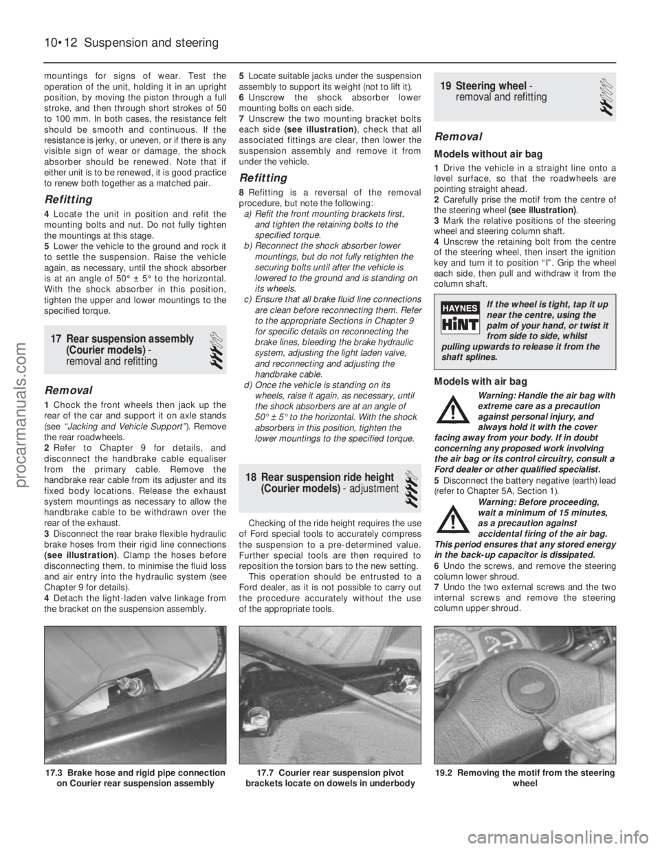
3 Disconnect the rear brake flexible hydraulic
brake hoses from their rigid line connections
(see illustration) . Clamp the hoses before
disconnecting them, to minimise the fluid loss
and air entry into the hydraulic system (see
Chapter 9 for details).
4 Detach the light-laden valve linkage from
the bracket on the suspension assembly. 5
Locate suitable jacks under the suspension
assembly to support its weight (not to lift it).
6 Unscrew the shock absorber lower
mounting bolts on each side.
7 Unscrew the two mounting bracket bolts
each side (see illustration) , check that all
associated fittings are clear, then lower the
suspension assembly and remove it from
under the vehicle.
Refitting
8 Refitting is a reversal of the removal
procedure, but note the following: a) Refit the front mounting brackets first,
and tighten the retaining bolts to the
specified torque.
b) Reconnect the shock absorber lower
mountings, but do not fully retighten the
securing bolts until after the vehicle is
lowered to the ground and is standing on
its wheels.
c) Ensure that all brake fluid line connections are clean before reconnecting them. Refer
to the appropriate Sections in Chapter 9
for specific details on reconnecting the
brake lines, bleeding the brake hydraulic
system, adjusting the light laden valve,
and reconnecting and adjusting the
handbrake cable.
d) Once the vehicle is standing on its
wheels, raise it again, as necessary, until
the shock absorbers are at an angle of
50° ± 5° to the horizontal. With the shock
absorbers in this position, tighten the
lower mountings to the specified torque.
18 Rear suspension ride height (Courier models) - adjustment
4
Checking of the ride height requires the use
of Ford special tools to accurately compress
the suspension to a pre-determined value.
Further special tools are then required to
reposition the torsion bars to the new setting.
This operation should be entrusted to a
Ford dealer, as it is not possible to carry out
the procedure accurately without the use
of the appropriate tools.
19 Steering wheel -
removal and refitting
2
Removal
Models without air bag
1 Drive the vehicle in a straight line onto a
level surface, so that the roadwheels are
pointing straight ahead.
2 Carefully prise the motif from the centre of
the steering wheel (see illustration).
3 Mark the relative positions of the steering
wheel and steering column shaft.
4 Unscrew the retaining bolt from the centre
of the steering wheel, then insert the ignition
key and turn it to position “I”. Grip the wheel
each side, then pull and withdraw it from the
column shaft.
Models with air bag
Warning: Handle the air bag with
extreme care as a precaution
against personal injury, and
always hold it with the cover
facing away from your body. If in doubt
concerning any proposed work involving
the air bag or its control circuitry, consult a
Ford dealer or other qualified specialist.
5 Disconnect the battery negative (earth) lead
(refer to Chapter 5A, Section 1).
Warning: Before proceeding,
wait a minimum of 15 minutes,
as a precaution against
accidental firing of the air bag.
This period ensures that any stored energy
in the back-up capacitor is dissipated.
6 Undo the screws, and remove the steering
column lower shroud.
7 Undo the two external screws and the two
internal screws and remove the steering
column upper shroud.
10•12 Suspension and steering
19.2 Removing the motif from the steering wheel17.7 Courier rear suspension pivot
brackets locate on dowels in underbody17.3 Brake hose and rigid pipe connection on Courier rear suspension assembly
1595Ford Fiesta Remake
If the wheel is tight, tap it up
near the centre, using the
palm of your hand, or twist it
from side to side, whilst
pulling upwards to release it from the
shaft splines.
procarmanuals.com
http://vnx.su
Page 216 of 296

4Pull the latch end of the cable into the
engine compartment, noting cable routing and
clips fitted. Remove the cable from its clips.
5 Detach the cable from its release lever on
the steering column, by aligning the cable
core with the slot on the release lever and
withdrawing the end fixing. Detach the cable
from its outer core abutment on the steering
column lock housing.
6 Unclip the cable from its pedal box
location, then detach the bulkhead grommet
and pass the cable through into the engine
compartment. Withdraw the cable from the
vehicle.
7 The release lever on the steering column
may be removed, if required, by unhooking
the spring from its retaining arms, then
disengaging its retaining arms from the
steering column lock housing.
Refitting
8 Refit the release lever, if removed, by
reversing the method of removal.
9 To install the release cable, first pass the
latch end of the cable down the right-hand
side of the steering column, through its
bulkhead location, and out into the engine
compartment.
10 Fit the cable to its clip on the pedal box
assembly, then reconnect the cable to the
release lever and the steering column lock
housing abutment by reversing the method of
removal.
11 Where applicable, refit the choke warning
light switch/pull control assembly, to the lower steering column shroud, by reversing the
method of removal. Refit the shroud.
12
Seat the release cable grommet into the
bulkhead.
13 Route and secure the release cable in the
engine compartment.
14 Reconnect the release cable to the latch,
then refit the latch to the body, setting the
latch at its maximum height position, and
tightening only the bottom retaining screw.
15 Adjust the latch for flush bonnet closure in
accordance with Section 8.
8 Bonnet latch - adjustment
1
1To adjust the bonnet latch, remove the two
upper latch retaining screws, then with the
latch raised to its maximum height position
and secured with the lower retaining screw,
close the bonnet.
2 Slacken the lower latch retaining screw,
through the gap between the leading edge of
the bonnet and the radiator grille slot, then
set the bonnet so it sits flush with its
surrounding panels - it may be necessary to
adjust the height of the bump stops (see
Section 6) if they have been moved in any
way, or if fitting a new bonnet.
3 With the desired bonnet closure obtained,
fully tighten the lower latch retaining screw,
then open the bonnet and refit the two upper
latch retaining screws, tightening to the
specified torque.
9 Body adhesive emblems -
renewal
1
1 Using a length of strong thin diameter cord
(fishing line is ideal), break the adhesive bond
between the emblem and the panel.
2 Thoroughly clean all traces of the old
adhesive from the emblem location, using
methylated spirit, taking all normal safety
precautions. Allow the emblem location to
dry.
3 Gently heat the new emblem until it is warm
to the touch. 4
Peel the protective backing paper from the
emblem then, taking care not to touch the
adhesive, position the emblem on the panel.
Maintain hand pressure evenly for at least
thirty seconds to ensure a good bond.
10 Body trim mouldings -
removal and refitting
1
Roof drip rail moulding (all
models except Courier)
Removal
1 Remove the drip rail moulding by gently
raising the forward end from its retaining
flange, taking care not to bend or kink it, then
carefully pull it off the retaining flange (see
illustration) .
Refitting
2To refit the drip rail moulding, first align the
rear of the moulding to the roof panel edge by
the tailgate, then, using the flat palm of the
hand, gently tap the moulding down.
3 If fitting the Ford roof rack, the drip rail
mouldings on both sides must be removed
and replaced by a ten-piece moulding kit,
available from Ford dealerships.
Roof drip rail moulding (Courier
models)
Removal
4 These are released by lifting and gripping
the moulding’s inboard edge, then by
rotating the whole length of the moulding
towards the outside of the vehicle to release it
from its outboard lip.
Refitting
5 Refitting is the reverse of the removal
procedure; ensure that the moulding’s
outboard edge is seated securely in its lip
before pressing the inboard edge firmly into
place.
Door side moulding
Removal
6 Apply masking tape, as an alignment guide
and to protect the paintwork, just above and
just below the moulding to be renewed.
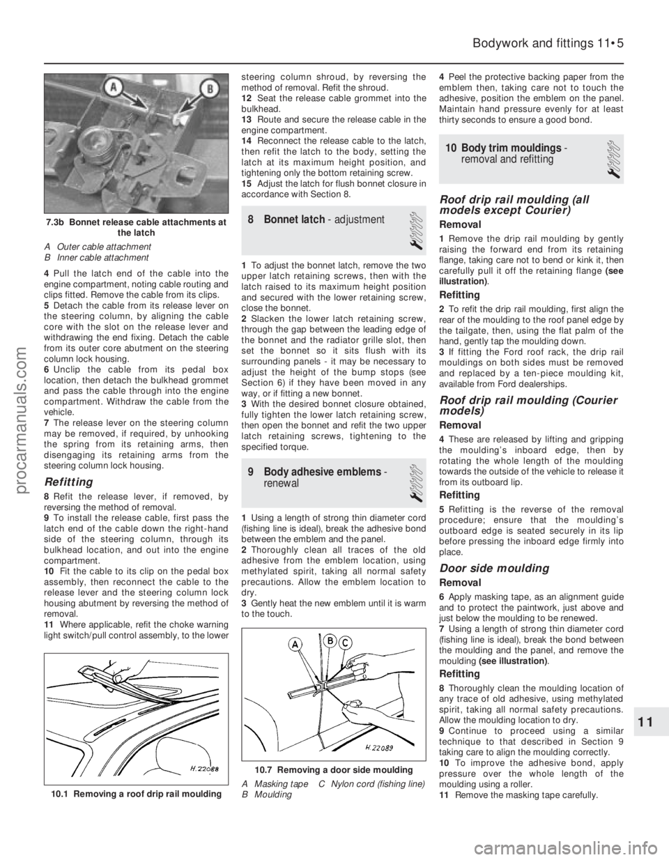
7 Using a length of strong thin diameter cord
(fishing line is ideal), break the bond between
the moulding and the panel, and remove the
moulding (see illustration) .
Refitting
8Thoroughly clean the moulding location of
any trace of old adhesive, using methylated
spirit, taking all normal safety precautions.
Allow the moulding location to dry.
9 Continue to proceed using a similar
technique to that described in Section 9
taking care to align the moulding correctly.
10 To improve the adhesive bond, apply
pressure over the whole length of the
moulding using a roller.
11 Remove the masking tape carefully.
Bodywork and fittings 11•5
7.3b Bonnet release cable attachments at
the latch
A Outer cable attachment
B Inner cable attachment
10.7 Removing a door side moulding
A Masking tape C Nylon cord (fishing line)
B Moulding
10.1 Removing a roof drip rail moulding
11
1595Ford Fiesta Remakeprocarmanuals.com
http://vnx.su