tow FORD FIESTA 2007 Workshop Manual
[x] Cancel search | Manufacturer: FORD, Model Year: 2007, Model line: FIESTA, Model: FORD FIESTA 2007Pages: 1226, PDF Size: 61.26 MB
Page 18 of 1226
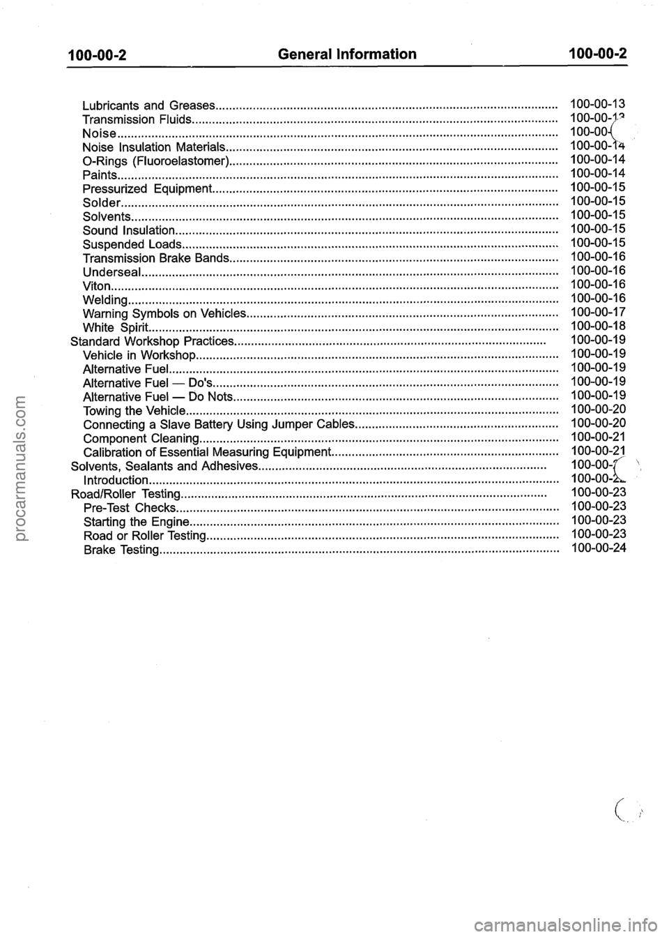
General Information
........................................................................\
............................. Lubricants and Greases
Transmission Fluids
........................................................................\
....................................
........................................................................\
.......................................................... Noise
Noise Insulation Materials
........................................................................\
..........................
0-Rings (Fluoroelastomer) ........................................................................\
.........................
........................................................................\
.......................................................... Paints
........................................................................\
.............................. Pressurized Equipment . . ........................................................................\
......................................................... Solder
........................................................................\
...................................................... Solvents
Sound Insulation
........................................................................\
.........................................
Suspended Loads ........................................................................\
.......................................
Transmission Brake Bands ........................................................................\
.........................
........................................................................\
................................................... Underseal
........................................................................\
............................................................ Viton
........................................................................\
....................................................... Welding
........................................................................\
.................... Warning Symbols on Vehicles
........................................................................\
................................................. White Spirit
Standard Workshop Practices
........................................................................\
....................
Vehicle in Workshop ........................................................................\
...................................
Alternative Fuel ........................................................................\
...........................................
Alternative Fuel - Do's ........................................................................\
..............................
Alternative Fuel - Do Nots ........................................................................\
........................
Towing the Vehicle ........................................................................\
......................................
Connecting a Slave Battery Using Jumper Cables ............................................................
Component Cleaning ........................................................................\
..................................
Calibration of Essential Measuring Equipment ...................................................................
Solvents. Sealants and Adhesives ........................................................................\
.............
........................................................................\
................................................. Introduction
RoadlRoller Testing ........................................................................\
....................................
Pre-Test Checks ........................................................................\
.........................................
Starting the Engine ........................................................................\
.....................................
Road or Roller Testing ........................................................................\
................................
Brake Testing ........................................................................\
..............................................
procarmanuals.com
Page 19 of 1226
100-00-3 General Information 100-00-3
DESCRIPTION AND OPERATION
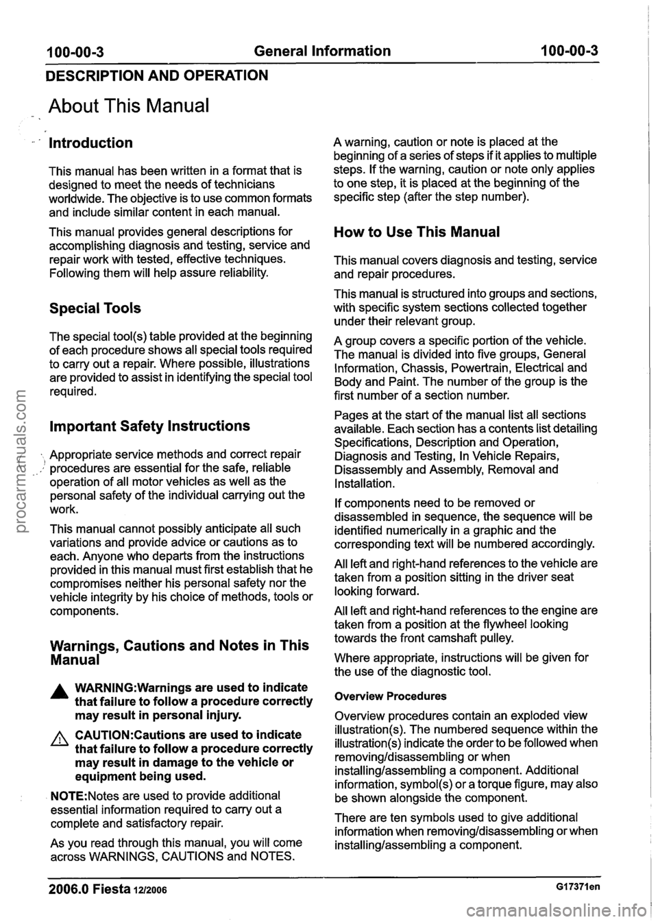
About This Manual
-- . Introduction
This manual has been written in a format that is
designed to meet the needs of technicians
worldwide. The objective is to use common formats
and include similar content in each manual.
This manual provides general descriptions for accomplishing diagnosis and testing, service and
repair work with tested, effective techniques.
Following them will help assure reliability.
Special Tools
The special tool(s) table provided at the beginning
of each procedure shows all special tools required
to carry out a repair. Where possible, illustrations
are provided to assist in identifying the special tool
required.
Important Safety Instructions
Appropriate service methods and correct repair
--.! procedures are essential for the safe, reliable
operation of all motor vehicles as well as the
personal safety of the individual carrying out the
work.
This manual cannot possibly anticipate all such
variations and provide advice or cautions as to
each. Anyone who departs from the instructions
provided in this manual must first establish that he
compromises neither his personal safety nor the
vehicle integrity by his choice of methods, tools or
components.
Warnings, Cautions and Notes in This
Manual
A WARN1NG:Warnings are used to indicate
that failure to follow a procedure correctly
may result in personal injury.
A warning, caution or note is placed at the
beginning of a series of steps if it applies to multiple
steps. If the warning, caution or note only applies
to one step, it is placed at the beginning of the
specific step (after the step number).
How to Use This Manual
This manual covers diagnosis and testing, service
and repair procedures.
This manual is structured into groups and sections,
with specific system sections collected together
under their relevant group.
A group covers a specific portion of the vehicle.
The manual is divided into five groups, General
Information, Chassis, Powertrain, Electrical and
Body and Paint. The number of the group is the
first number of a section number.
Pages at the start of the manual list all sections
available. Each section has a contents list detailing
Specifications, Description and Operation,
Diagnosis and Testing, In Vehicle Repairs,
Disassembly and Assembly, Removal and
Installation.
If components need to be removed or
disassembled in sequence, the sequence will be
identified numerically in a graphic and the
corresponding text will be numbered accordingly.
All left and right-hand references to the vehicle are
taken from a position sitting in the driver seat
looking forward.
All left and right-hand references to the engine are
taken from a position at the flywheel looking
towards the front camshaft pulley.
Where appropriate, instructions will be given for
the use of the diagnostic tool.
Overview Procedures
Overview procedures contain an exploded view
A CAUTI0N:Cautions are used to indicate illustration(s). The numbered sequence within the
that failure to follow a procedure correctly illustration(s) indicate the order to be followed when
may result in damage to the vehicle or removingldisassem bling or when
equipment being used. installinglassembling a component. Additional
information,
symbol(s) or a torque figure, may also
, , N0TE:Notes are used to provide additional
be shown alonaside the com~onent.
essential information required to carry out a
complete and satisfactory repair. There are
ten symbols used to give additional
information when
removina/disassemblincr or when V AS YOU read through this manual, YOU will come /"itallinglassembling a c&ponent.
across WARNINGS, CAUTIONS and NOTES.
2006.0 Fiesta 1212006 GI 7371 en
procarmanuals.com
Page 36 of 1226
100-00-20 General Information 100-00-20
DESCRIPTION AND OPERATION
Towing the Vehicle
an instance, the discharged battery must
be recharged immediately after jump
A WARN1NG:When the vehicle is being starting
to avoid permanent damage. ( towed, the ignition switch must be in - Always make sure that the jumper cables are
position ll (steering lock released and adequate for the task. Heavy duty cables must
warning lamps illuminated). Only then will be used.
the turn signal lamps, horn and - Always make sure that the slave battery is of stop lamps be operational. Failure to follow the same voltage as the vehicle battery. The these instructions may result in personal batteries must be connected in parallel. injury. - Always make sure that switched electric circuits
N0TE:The removable towing eye (if equipped),
are switched off before connecting jumper
has a left-hand thread and must be fully tightened cables. This reduces the risk of arcing occurring
before towing can commence.
when the final connection is made.
When towing is necessary, the vehicle towing eyes
should be used. The rope must be securely
fastened to the towing eyes and must also be
attached to the other vehicle such that the rope will
not foul the bodywork.
When a vehicle with automatic transmission is
towed, the gear selector must be in position
N
(Neutral). Never tow a vehicle with automatic
transmission at a speed greater than 30 mph (50
kmlh) or for a distance greater than 30 miles (50
km). If it is necessary to tow the vehicle a greater
distance, the drive wheels must be lifted clear off
the ground.
I A WARN1NG:Make sure that the ends of the Alternatively the vehicle can be transported on a jumper cables do not touch each other or low loader or a trailer. ground against the vehicle body at any
time while the cables are attached to the
Connectin a Slave Battery Using
73
battery. A fully charged battery, if shorted
Jumper Ca les through jumper cables, can discharge at
a rate well above
I000 amps causing
A WARNING:H the slave battery has recently violent arcing
and very rapid heating of the
been charged and is gassing, cover the jumper cables and
terminals, and can even
vent plugs or covers with a damp cloth to cause
the battery to explode. Failure to
reduce the risk of explosion should arcing follow
these instructions may result in
occur when connecting the jumper cables. personal injury.
Failure to follow these instructions may
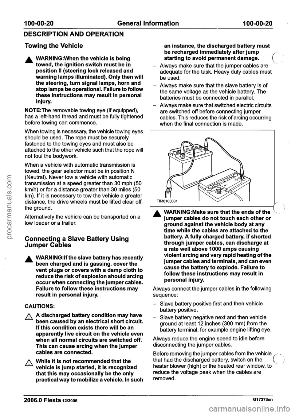
Always connect the jumper cables in the following
result in personal injury. sequence:
CAUTIONS:
A A discharged battery condition may have
been caused by an electrical short circuit.
If this condition exists there will be an
apparently live circuit on the vehicle even
when all normal circuits are switched off.
This can cause arcing when the jumper
cables are connected.
A While it is not recommended that the
vehicle is jump started,
it is recognized
that this may occasionally be the only
practical way to mobilize a vehicle. In such
- Slave battery positive first and then vehicle
battery positive.
- Slave battery negative next and then vehicle
ground at least
12 inches (300 mm) from the
battery terminal, for example engine lifting eye.
Always reduce the engine speed to idle before
disconnecting the jumper cables.
Before removing the jumper cables from the vehicle
-
heater blower (high) or the heated rear window, to
that
had the discharged battery, switch on the
reduce the voltage peak when the cables are
removed.
2006.0 Fiesta 1~12006 GI 7373en
procarmanuals.com
Page 120 of 1226
204-01 -22 Front Suspension 204101 122
REMOVAL AND INSTALLATION
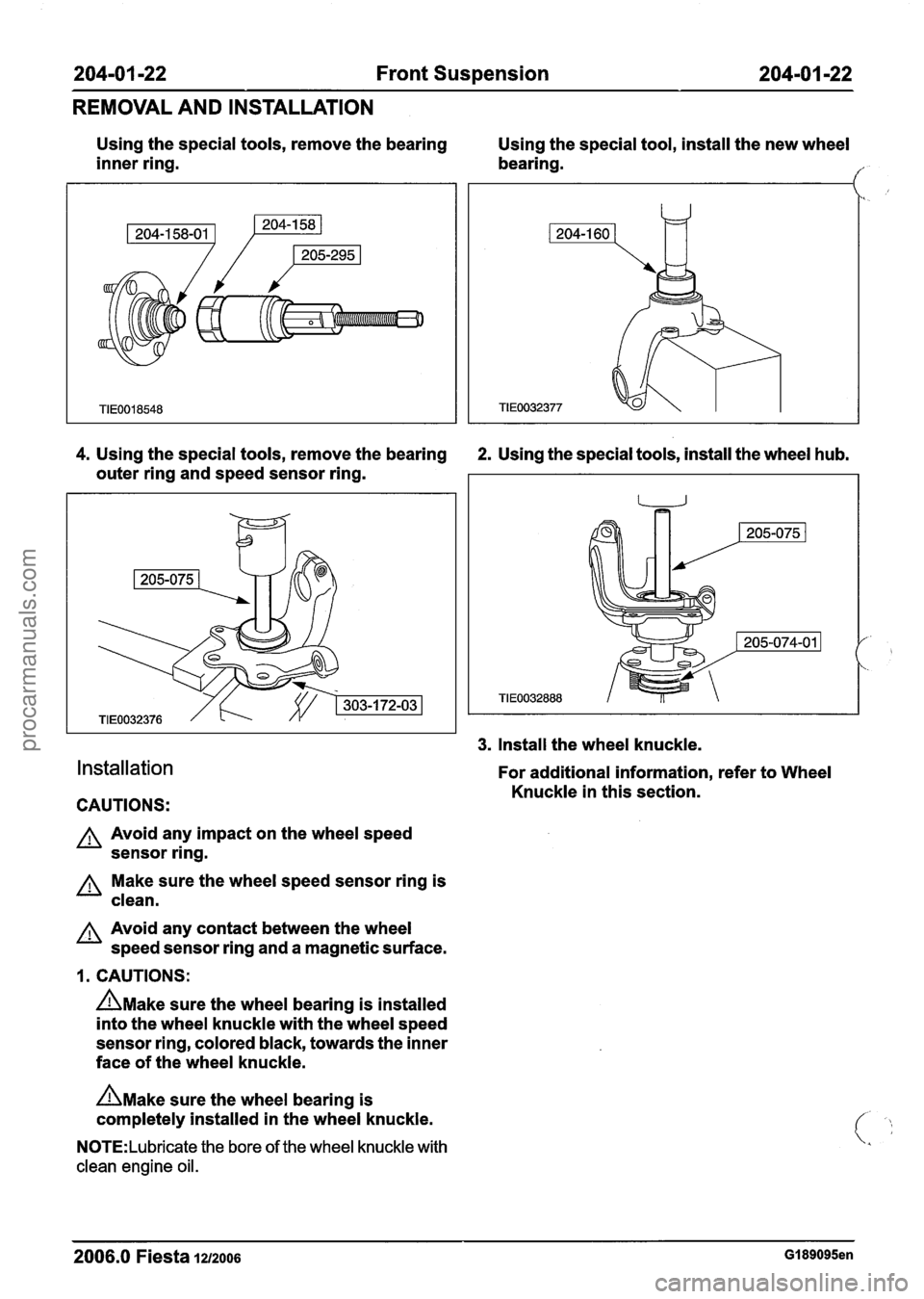
Using the special tools, remove the bearing
Using the special tool, install the new wheel
inner ring. bearing.
I"
4. Using the special tools, remove the bearing 2. Using the special tools, install the wheel hub.
outer ring and speed sensor ring.
Installation
CAUTIONS:
A Avoid any impact on the wheel speed
sensor ring.
Make sure the wheel speed sensor ring is
clean.
A Avoid any contact between the wheel
speed sensor ring and a magnetic surface.
1. CAUTIONS:
n~ake sure the wheel bearing is installed
into the wheel knuckle with the wheel speed
sensor ring, colored black, towards the inner
face of the wheel knuckle.
n~ake sure the wheel bearing is
completely installed in the wheel knuckle.
N0TE:Lubricate the bore of the wheel knuckle with
clean engine oil.
3. Install the wheel knuckle.
For additional information, refer to Wheel
Knuckle in this section.
--
2006.0 Fiesta 1212006 GI 89095en
procarmanuals.com
Page 157 of 1226
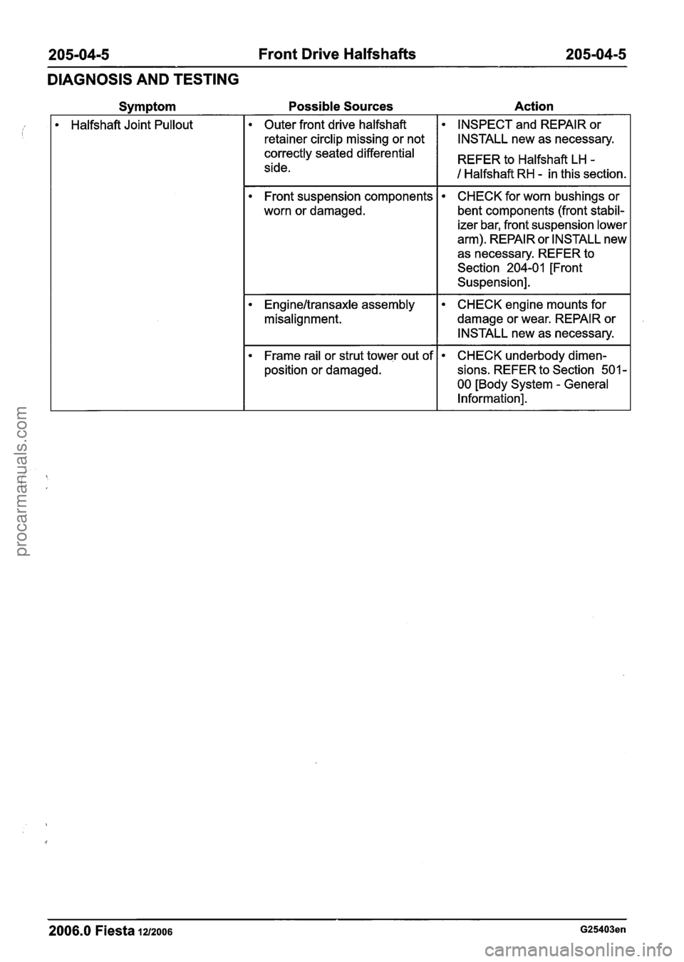
205-04-5 Front Drive Halfshafts 205-04-5
DIAGNOSIS AND TESTING
Possible Sources Action
Halfshaft Joint Pullout Outer front drive halfshaft INSPECT
and REPAIR or
retainer circlip missing or not
I I INSTALL new as necessary.
Front suspension components
worn or damaged.
correctly seated differential
side. CHECK
for worn bushings or
bent components (front stabil-
izer bar, front suspension lower
arm). REPAIR or INSTALL new
as necessary. REFER to
Section
204-01 [Front
Suspension]. REFER to Halfshaft
LH
-
1 Halfshaft RH - in this section.
Engineltransaxle assembly
misalignment. CHECK engine mounts for
damage or wear. REPAIR or
INSTALL new as necessary.
Frame rail or strut tower out of
position or damaged. CHECK underbody dimen-
sions. REFER to Section
501 -
00 [Body System - General
Information].
-- - --
2006.0 Fiesta 1212006 G25403en
procarmanuals.com
Page 168 of 1226
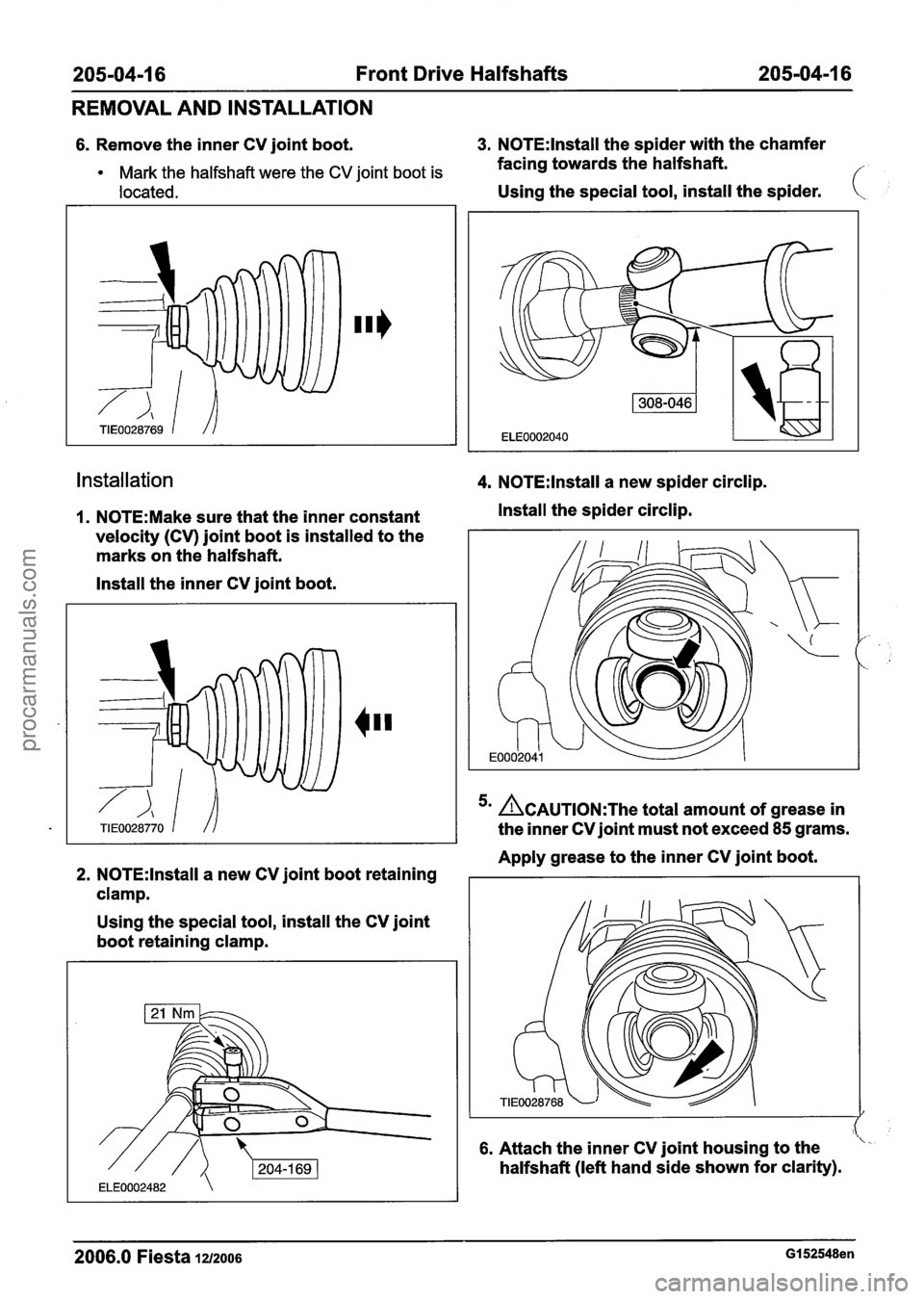
205-04-1 6 Front Drive Halfshafts 205-04-1 6
REMOVAL AND INSTALLATION
6. Remove the inner CV joint boot. 3. N0TE:lnstall the spider with the chamfer
Mark the halfshaft were the CV joint boot is facing towards the halfshaft.
located. Using the special tool, install the spider. (
installation 4. N0TE:lnstall a new spider circlip.
I. N0TE:Make sure that the inner constant Install the spider circlip.
velocity (CV) joint boot is installed to the
marks on the halfshaft.
Install the inner CV joint boot.
'' ACAUTION:T~~ total amount of grease in
the inner CV joint must not exceed
85 grams.
Apply grease to the inner CV joint boot.
2. N0TE:lnstall a new CV joint boot retaining I I
clamp.
Using the special tool, install the CV joint
boot retaining clamp.
6. Attach the inner CV joint housing to the
halfshaft (left hand side shown for clarity).
2006.0 Fiesta iu200s GI 52548en
procarmanuals.com
Page 209 of 1226
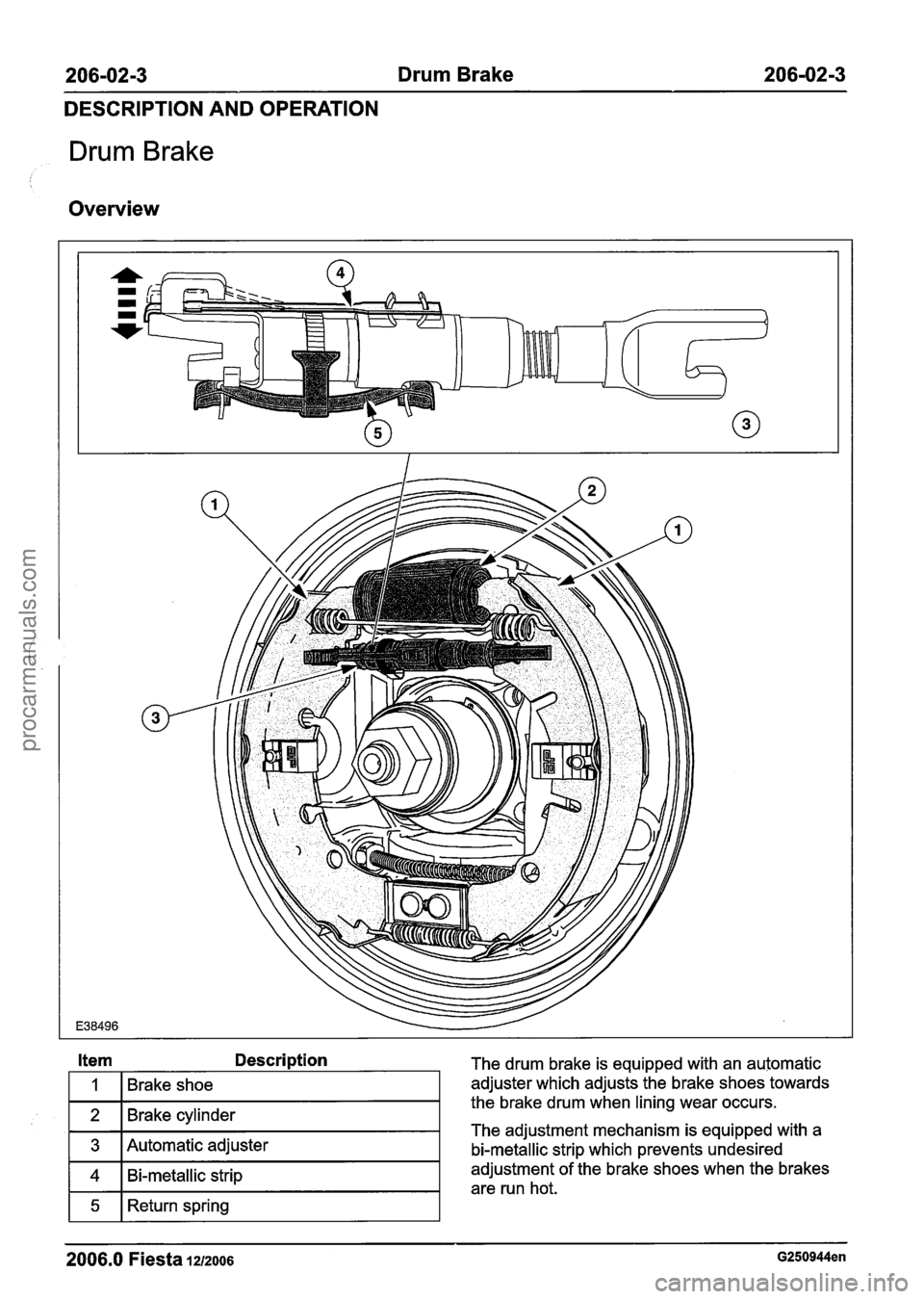
206-02-3 Drum Brake 206-02-3
DESCRIPTION AND OPERATION
Drum Brake
Overview
2006.0 Fiesta 1212006 G250944en
Item Description The drum brake is equipped with an automatic
adjuster which adjusts the brake shoes towards
the brake drum when lining wear occurs.
The adjustment mechanism is equipped with a
bi-metallic strip which prevents undesired
adjustment of the brake shoes when the brakes
are run hot.
1
2
3
4
5
Brake shoe
Brake cylinder
Automatic adjuster
Bi-metallic strip
Return spring
procarmanuals.com
Page 260 of 1226
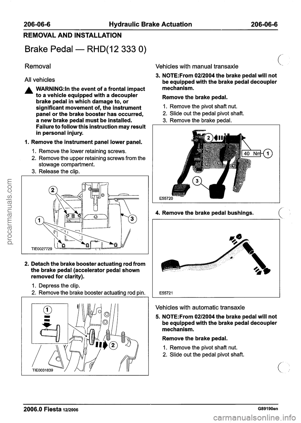
206-06-6 Hydraulic Brake Actuation 206-06-6
REMOVAL AND INSTALLATION
Brake Pedal - RHD(12 333 0)
Removal
All vehicles
A WARNING:ln the event of a frontal impact
to a vehicle equipped with a decoupler
brake pedal in which damage to, or
significant movement of, the instrument
panel or the brake booster has occurred,
a new brake pedal must be installed.
Failure to follow this instruction may result
in personal injury.
1. Remove the instrument panel lower panel.
1. Remove the lower retaining screws.
2. Remove the upper retaining screws from the
stowage compartment.
3. Release the clip.
2. Detach the brake booster actuating rod from
the brake pedal (accelerator pedal shown
removed for clarity).
I. Depress the clip.
2. Remove the brake booster actuating rod pin.
Vehicles with manual transaxle 1.
3. N0TE:From 0212004 the brake pedal will not
be equipped with the brake pedal decoupler
mechanism.
Remove the brake pedal.
1. Remove the pivot shaft nut.
2. Slide out the pedal pivot shaft.
3. Remove the brake pedal.
4. Remove the brake pedal bushings. ( ,:
Vehicles with automatic transaxle
5. N0TE:From 0212004 the brake. pedal will not
be equipped with the brake pedal decoupler
mechanism.
Remove the brake pedal.
1. Remove the pivot shaft nut.
2. Slide out the pedal pivot shaft.
2006.0 Fiesta 1212006 G89190en
procarmanuals.com
Page 272 of 1226
206-07-8 Power Brake Actuation 206-07-8
REMOVAL AND INSTALLATION
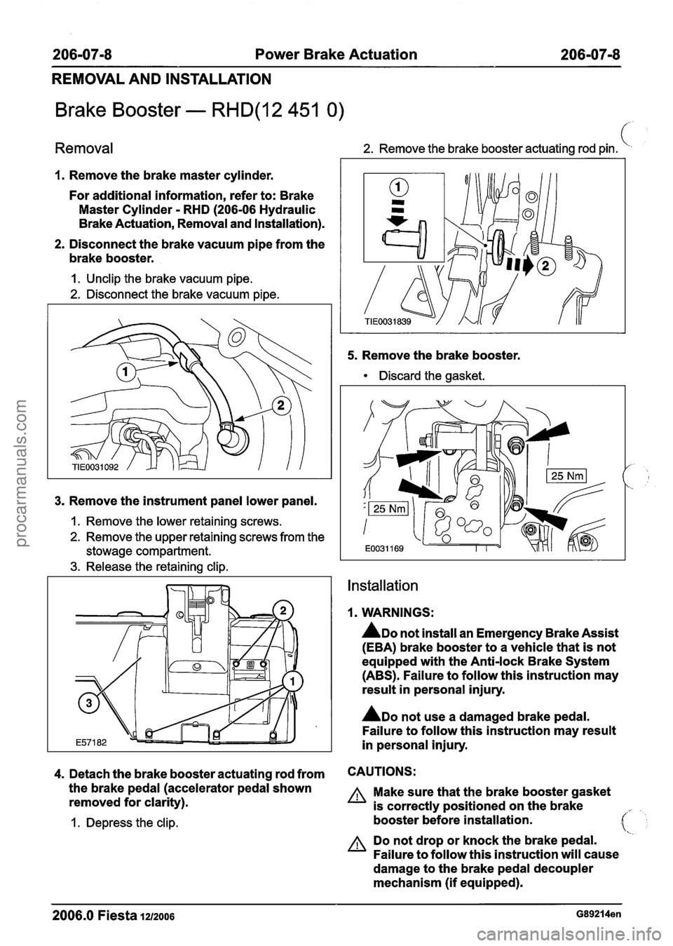
Brake Booster - RHD(12 451 0)
Removal 2. Remove the brake booster actuating rod pin. (
1. Remove the brake master cylinder.
For additional information, refer to: Brake
Master Cylinder
- RHD (206-06 Hydraulic
Brake Actuation, Removal and Installation).
2. Disconnect the brake vacuum pipe from the
brake booster.
I. Unclip the brake vacuum pipe.
2. Disconnect the brake vacuum pipe.
3. Remove the instrument panel lower panel.
1. Remove the lower retaining screws.
2. Remove the upper retaining screws from the
stowage compartment.
3. Release the retaining clip. 5.
Remove
the brake booster.
Discard the gasket.
Installation
1. WARNINGS:
ADO not install an Emergency Brake Assist
(EBA) brake booster to a vehicle that is not
equipped with the Anti-lock Brake System
(ABS). Failure to follow this instruction may
result in personal injury.
ADO not use a damaged brake pedal.
Failure to follow this instruction may result
in personal injury.
4. Detach the brake booster actuating rod from CAUTIONS:
the brake pedal (accelerator pedal shown A Make sure that the brake booster gasket
removed for clarity).
is correctly positioned on the brake
I. Depress the clip. booster before installation. 41
A Do not drop or knock the brake pedal.
Failure to follow this instruction will cause
damage to the brake pedal decoupler
mechanism (if equipped).
2006.0 Fiesta 12/2006 G89214en
procarmanuals.com
Page 413 of 1226
21 1 -04-5 Steering Column 2 I I -04-5
REMOVAL AND INSTALLATION
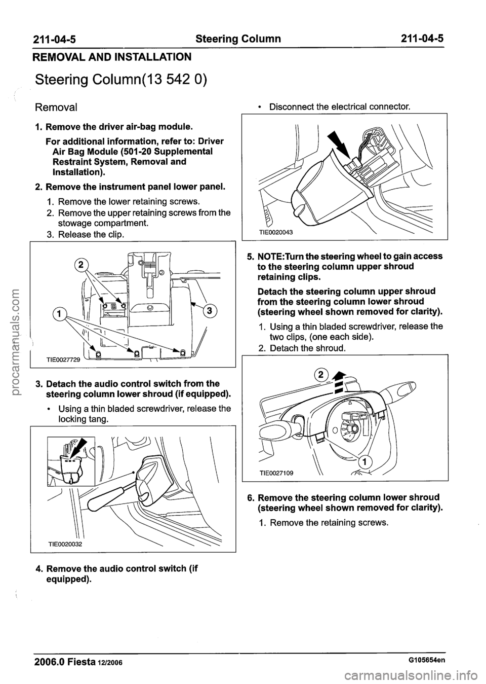
Steering Column(l3 542 0)
Removal Disconnect the electrical connector.
1. Remove the driver air-bag module.
For additional information, refer to: Driver
Air Bag Module (501-20 Supplemental
Restraint System, Removal and
Installation).
2. Remove the instrument panel lower panel.
1. Remove the lower retaining screws.
2. Remove the upper retaining screws from the
stowage compartment.
3. Release the clip.
3. Detach the audio control switch from the
steering column lower shroud (if equipped).
Using a thin bladed screwdriver, release the
locking tang.
4. Remove the audio control switch (if
equipped).
5. N0TE:Turn the steering wheel to gain access
to the steering column upper shroud
retaining clips.
Detach the steering column upper shroud
from the steering column lower shroud (steering wheel shown removed for clarity).
1 . Using a thin bladed screwdriver, release the
two clips, (one each side).
2. Detach the shroud.
6. Remove the steering column lower shroud
(steering wheel shown removed for clarity).
1. Remove the retaining screws.
2006.0 Fiesta 1212006 GI 05654en
procarmanuals.com