accessory FORD FIESTA 2007 User Guide
[x] Cancel search | Manufacturer: FORD, Model Year: 2007, Model line: FIESTA, Model: FORD FIESTA 2007Pages: 1226, PDF Size: 61.26 MB
Page 358 of 1226
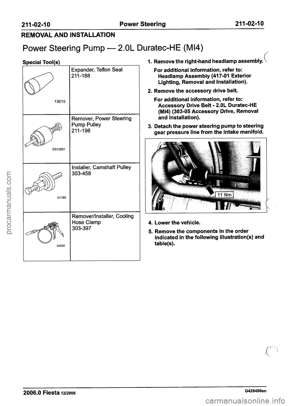
21 1-02-1 0 Power Steering 21 1-02-1 0
REMOVAL AND INSTALLATION
Power Steering Pump - 2.OL Duratec-HE (M14)
f
I I Remover, Power Steering I
1 I Installer, Camshaft Pulley 1
7 I Removerllnstaller, Cooling I
1. Remove the right-hand headlamp assembly.
For additional information, refer to:
Headlamp Assembly (41 7-01 Exterior
Lighting, Removal and Installation).
2. Remove the accessory drive belt.
For additional information, refer to:
Accessory Drive Belt
- 2.OL Duratec-HE
(M14) (303-05 Accessory Drive, Removal
and Installation).
I
3. Detach the power steering pump to steering
, gear pressure line from the intake manifold. I
1 4. Lower the vehicle.
5. Remove the components in the order
indicated in the following
illustration(s) and
table(s).
2006.0 Fiesta 1212006 G428496en
procarmanuals.com
Page 369 of 1226
21 1-02-21 Power Steering 21 1-02-21
REMOVAL AND INSTALLATION
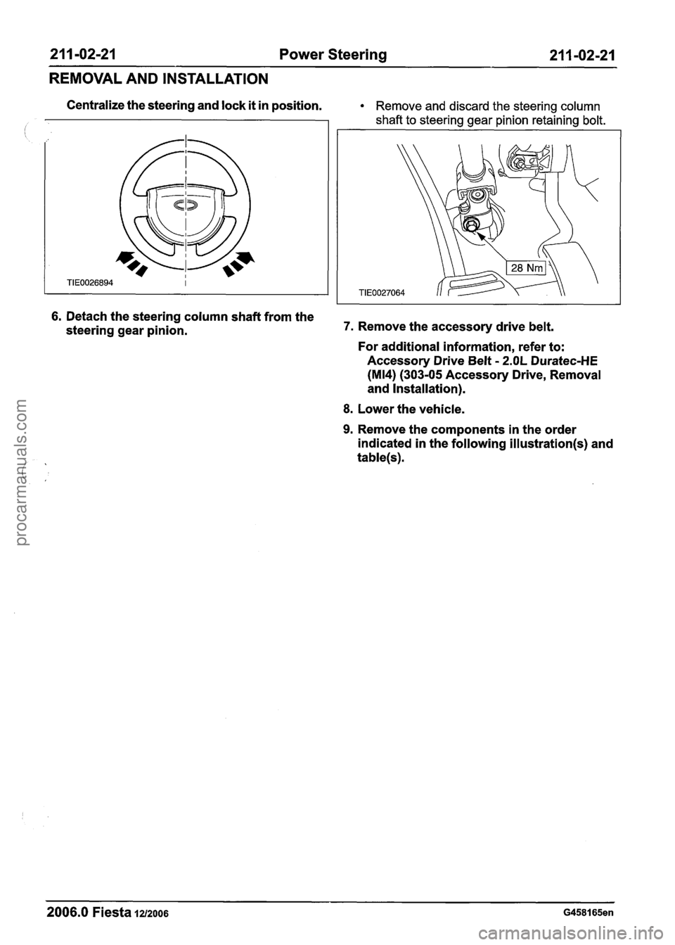
Centralize the steering and lock it in position. Remove and discard the steering column
shaft to steering gear pinion retaining bolt.
6. Detach the steering column shaft from the
steering gear pinion. 7. Remove the accessory drive belt.
For additional information, refer to:
Accessory Drive Belt
- 2.OL Duratec-HE
(M14) (303-05 Accessory Drive, Removal
and Installation).
8. Lower the vehicle.
9. Remove the components in the order
indicated in the following
illustration(s) and
table(s).
2006.0 Fiesta 1212006 G458165en
procarmanuals.com
Page 495 of 1226
Engine - 1.25L Duratec-I 6V (Sigma)ll.4L
303-01A-I 9 Duratec-1 6V (Sigma)/l .6L Duratec-1 6V (Sigma) 303-OIA-I 9
IN-VEHICLE REPAIR
Intake Manifold(21 183 0)
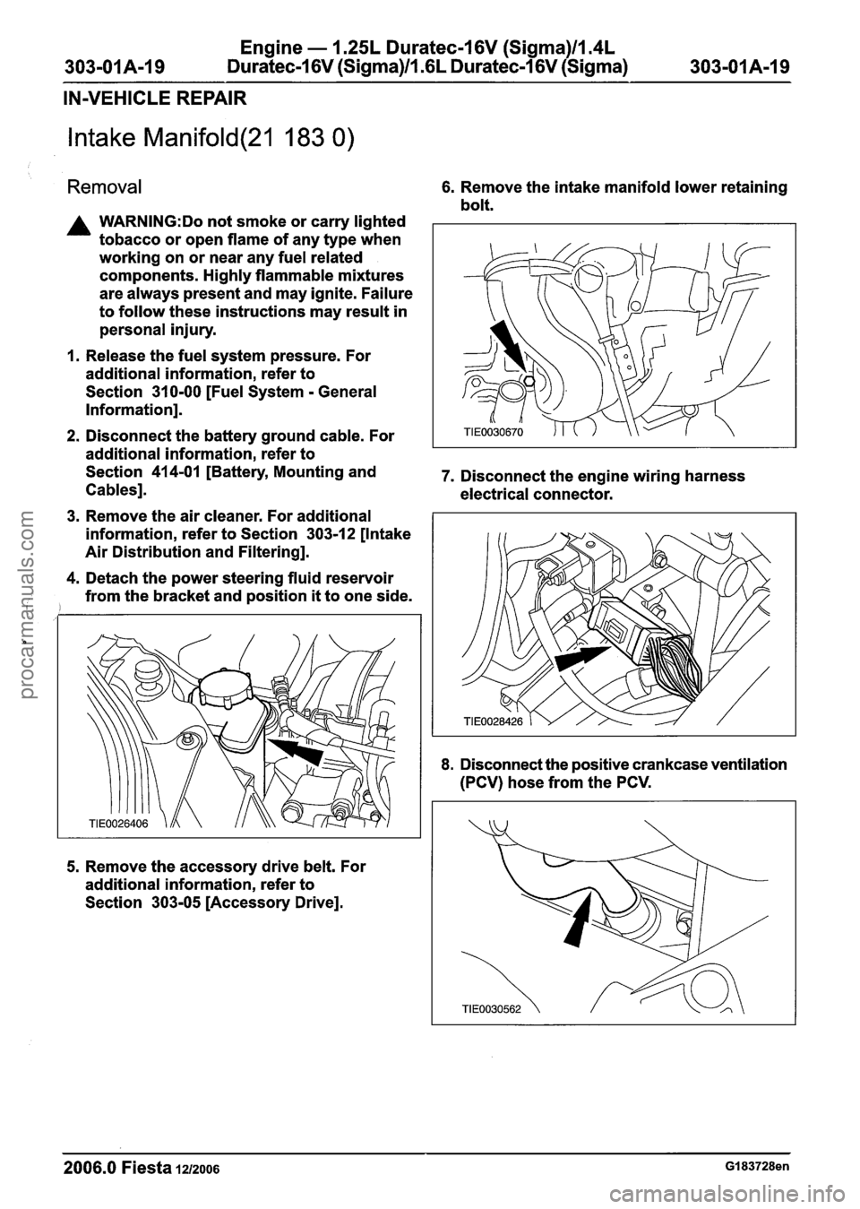
Removal 6. Remove the intake manifold lower retaining
bolt.
A WARNING:Do not smoke or carry lighted
tobacco or open flame of any type when
working on or near any fuel related
components. Highly flammable mixtures
are always present and may ignite. Failure
to follow these instructions may result in
personal injury.
1. Release the fuel system pressure. For
additional information, refer to
Section
31 0-00 [Fuel System - General
Information].
2. Disconnect the battery ground cable. For
additional information, refer to
Section
414-01 [Battery, Mounting and 7. Disconnect the engine wiring harness
Cables]. electrical connector.
3. Remove the air cleaner. For additional
information, refer to Section
303-1 2 [Intake
Air Distribution and Filtering].
4. Detach the power steering fluid reservoir
from the bracket and position
it to one side.
5. Remove the accessory drive belt. For
additional information, refer to
Section
303-05 [Accessory Drive].
8. Disconnect the positive crankcase ventilation
(PCV) hose from the PCV.
2006.0 Fiesta 1212006 GI 83728en
procarmanuals.com
Page 502 of 1226
Engine - 1.25L Duratec-1 6V (Sigma)ll.4L
303-01 A-26 Duratec-1 6V (Sigma)Il.GL Duratec-1 6V (Sigma) 303-01 A-26
IN-VEHICLE REPAIR
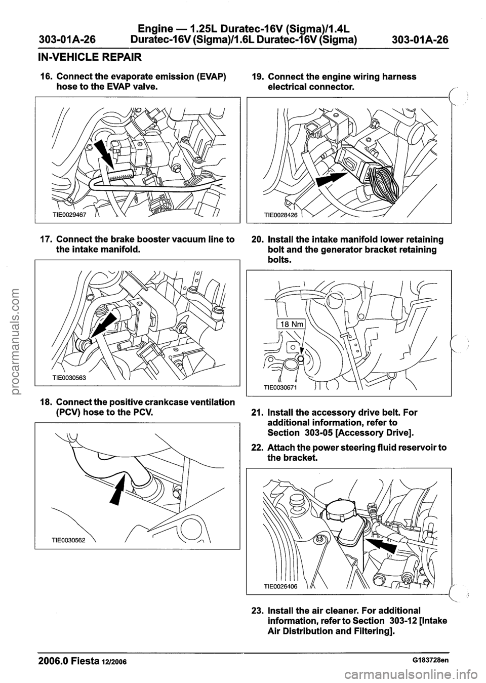
16. Connect the evaporate emission (EVAP)
hose to the EVAP valve.
17. Connect the brake booster vacuum line to
the intake manifold.
19. Connect the engine wiring harness
electrical connector.
20. Install the intake manifold lower retaining
bolt and the generator bracket retaining
bolts.
18. Connect the positive crankcase ventilation
(PCV) hose to the PCV.
21. Install the accessory drive belt. For
additional information, refer to
Section
303-05 [Accessory Drive].
22. Attach the power steering fluid reservoir to
the bracket.
23. Install the air cleaner. For additional
information, refer to Section
3031 2 [Intake
Air Distribution and Filtering].
2006.0 Fiesta 1212006 GI 83728en
procarmanuals.com
Page 513 of 1226
Engine - 1.25L Duratec-1 6V (Sigma)lIl4L
303-01 A-37 Duratec-1 6V (Sigma)ll.GL Duratec-1 6V (Sigma) 303-01A-37
IN-VEHICLE REPAIR
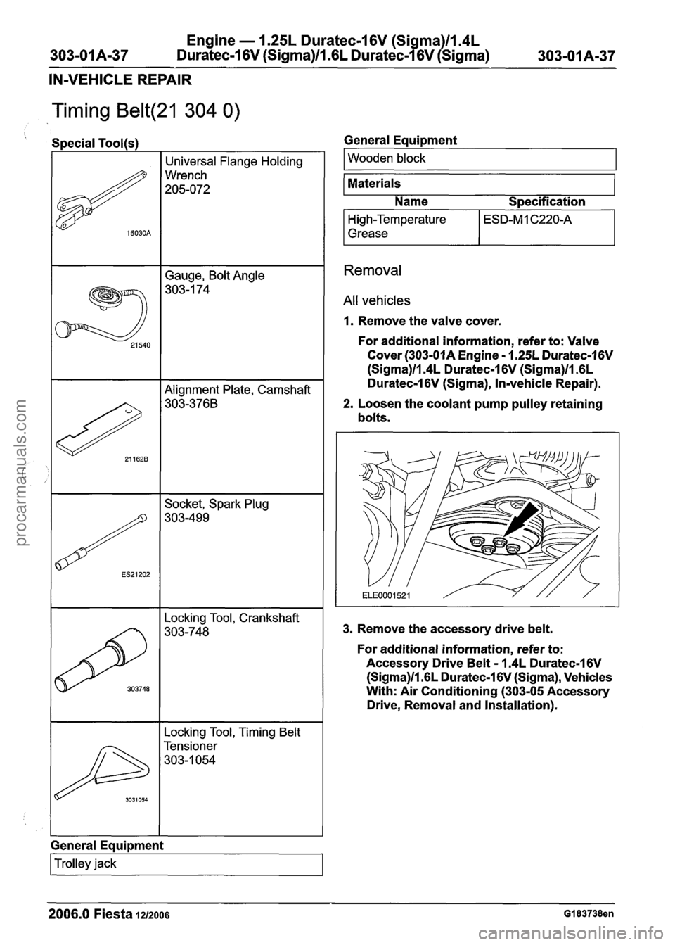
Timing Belt(21 304 0)
Gauge, Bolt Angle
303-1 74
' Special Tool(s)
# 15030A
Locking Tool, Timing Belt
I Tensioner
303-1054
Universal Flange Holding
Wrench
205-072
303748
General Equipment
Locking Tool, Crankshaft
303-748
I Trolley jack I
General Eaui~ment
I Wooden block I - --
Materials
Name
S~ecification
High-Temperature
Grease
Removal
All vehicles
1. Remove the valve cover.
For additional information, refer to: Valve
Cover
(303-01A Engine - 1.25L Duratec-1 6V
(Sigma)ll.4L Duratec-1 6V (Sigma)ll .6L
Duratec-1
6V (Sigma), In-vehicle Repair).
2. Loosen the coolant pump pulley retaining
bolts.
3. Remove the accessory drive belt.
For additional information, refer to:
Accessory Drive Belt
- 1.4L Duratec-I 6V
(Sigma)/l.GL Duratec-1 6V (Sigma), Vehicles
With: Air Conditioning (303-05 Accessory
Drive, Removal and Installation).
2006.0 Fiesta 1212006 GI 83738en
procarmanuals.com
Page 521 of 1226

Engine - I .25L Duratec-1 6V (Sigma)llm4L
303-01A-45 Duratec-1 6V (Sigma)/l .6L Duratec-1 6V (Sigma) 303-01 A-45
IN-VEHICLE REPAIR
lnstall the engine front mount.
27. Remove the
trolley jack.
28. Attach the generator.
1. lnstall the stud and nut.
2. lnstall the bolt.
3. Tighten the bolt.
31. lnstall the timing belt upper cover retaining
bolts.
32. N0TE:Do not tighten the coolant pump
pulley retaining bolts at this stage.
lnstall the coolant pump pulley.
I 33. lnstall the accessory drive belt.
29. Connect the generator electrical connector.
For additional information, refer to:
Accessory Drive
Belt - 1.4L Duratec-1 6V
(Sigma)ll.GL Duratec-1 6V (Sigma),
Vehicles With: Air Conditioning (303-05
Accessory Drive,
Removal and
Installation).
30. Raise and support the vehicle.
For additional information, refer to: Lifting
(100-02 Jacking and Lifting, Description
and Operation).
2006.0 Fiesta 1212006 GI 83738en
procarmanuals.com
Page 552 of 1226
Engine - 1.25L Duratec-1 6V (Sigma)ll.4L
303-01 A-76 Duratec-1 6V (Sigma)lll6L Duratec-1 6V (Sigma) 303-01 A-76
REMOVAL
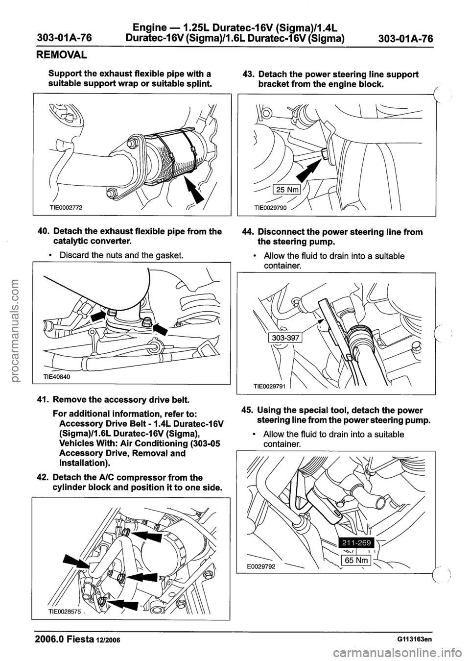
Support the exhaust flexible pipe with a
suitable support wrap or suitable splint. 43.
Detach the power steering line support
bracket from the engine block.
/' -
40. Detach the exhaust flexible pipe from the
44. Disconnect the power steering line from
catalytic converter. the steering pump.
Discard the nuts and the gasket.
Allow the fluid to drain into a suitable
container.
41. Remove the accessory drive belt.
For additional information, refer to: 45.
Using the special tool, detach the power
Accessory Drive Belt
- I .4L Duratec-16V steering line from the power steering pump.
(Sigma)ll.GL Duratec-1 6V (Sigma), Allow the fluid to drain into a suitable
Vehicles With: Air Conditioning (303-05 container.
Accessory Drive, Removal and
Installation).
42. Detach the
AIC compressor from the
cylinder block and position
it to one side.
2006.0 Fiesta 1212006 GII 31 63en
procarmanuals.com
Page 565 of 1226

Engine - 1.25L Duratec-1 6V (Sigma)ll.4L
303-01 A-89 Duratec-1 6V (Sigma)ll.GL Duratec-1 6V (Sigma) 303-01 A-89
REMOVAL
44m ACAUTION:~~~~ bending of the exhaust Vehicles with air conditioning
I flexible pipe may cause damage resulting 47.
Disconnect the air conditioning (NC)
, in failure. low-pressure cutoff switch electrical
Support the exhaust
flexible pipe with a connector.
suitable support
wrap or suitable splint.
48. Disconnect the NC compressor clutch
45. Detach the exhaust flexible pipe from the electrical connector.
catalytic converter.
Discard the nuts and the gasket.
46. Remove the accessory drive belt.
For additional information, refer to:
Accessory Drive
Belt - I .4L Duratec-I 6V
(Sigma)ll .6L Duratec-1 6V (Sigma),
Vehicles With: Air Conditioning (303-05
Accessory Drive, Removal and
Installation)
I Accessory Drive Belt - I .4L Duratec-I 6V
(Sigma)ll .6L Duratec-1 6V (Sigma),
Vehicles Without: Air Conditioning
(303-05 Accessory Drive,
Removal and
Installation).
49. Disconnect the NC high-pressure cutoff
switch
electrical connector.
2006.0 Fiesta 1212006 G380458en
procarmanuals.com
Page 602 of 1226

303-01 A-I 26 Engine
- 1.25L Duratec-I 6V (Sigma)ll.4L
Duratec-1 6V (Sigma)ll .6L
Duratec-1 6V (Sigma) 303-01A-I26
INSTALLATION
23. Attach the air conditioning (NC)
compressor to the
cylinder block.
27. Connect the reversing lamp switch
electrical connector.
I
24. Connect the NC compressor clutch
28. Connect the crankshaft position (CKP)
electrical connector. sensor electrical connector.
25. Install the accessory drive belt. 29. Connect the oil pressure switch electrical
For
additional information, refer to: connector.
Accessory Drive
Belt - I .4L Duratec-16V
(Sigma)ll .6L Duratec-1 6V (Sigma),
Vehicles With: Air Conditioning (303-05
Accessory Drive,
Removal and
Installation).
26. Connect the starter motor electrical
connectors.
30.
N0TE:lnstall new exhaust flange nuts and
a new exhaust
flange gasket.
2006.0 Fiesta 1212006 Gll3164en
procarmanuals.com
Page 615 of 1226

Engine - 1.25L Duratec-1 6V (Sigma)ll.4L
303-01 A-1 39 Duratec-I 6V (Sigma)ll .6L Duratec-1 6V (Sigma) 303-01 A-I 39
INSTALLATION
Vehicles with air conditioning
28. Attach the air conditioning (AIC)
compressor to the cylinder block. 31.
Connect the air conditioning (AIC)
low-pressure cutoff switch electrical
connector.
29. Connect the
AIC high-pressure cutoff All vehicles
switch electrical connector. 32.
Install the accessory drive belt.
For additional information, refer to:
Accessory Drive Belt
- 1.4L Duratec-16V
(Sigma)ll.GL Duratec-1 6V (Sigma),
Vehicles With: Air Conditioning
(303-05
Accessory Drive, Removal and
Installation)
I Accessory Drive Belt - 1.4L Duratec-1 6V
(Sigma)ll.GL Duratec-1 6V (Sigma),
Vehicles Without: Air Conditioning
(303-05 Accessory Drive, Removal and
Installation).
33. Lower the vehicle.
34. Tighten the engine front mount retaining
30. Connect the
AIC compressor clutch
nuts and bolts.
electrical connector.
2006.0 Fiesta 1212006 G380459en
procarmanuals.com