instrument cluster FORD FIESTA 2007 User Guide
[x] Cancel search | Manufacturer: FORD, Model Year: 2007, Model line: FIESTA, Model: FORD FIESTA 2007Pages: 1226, PDF Size: 61.26 MB
Page 932 of 1226
Electronic Engine Controls
DESCRIPTION AND OPERATION
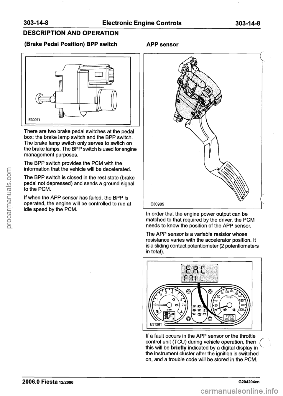
(Brake Pedal Position) BPP switch
APP sensor
There are two brake pedal switches at the pedal
box: the brake lamp switch and the BPP switch.
The brake lamp switch only serves to switch on
the brake lamps. The BPP switch is used for engine
management purposes.
The BPP switch provides the PCM with the
information that the vehicle will be decelerated.
The BPP switch is closed in the rest state (brake
pedal not depressed) and sends a ground signal
to the PCM.
If when the APP sensor has failed, the BPP is
operated, the engine will be controlled to run at
idle speed by the PCM.
In order that the engine power output can be
matched to that required by the driver, the PCM
needs to know the position of the APP sensor.
The APP sensor is a variable resistor whose
resistance varies with the accelerator position. It
is a sliding contact potentiometer
(2 potentiometers
in total).
If a fault occurs in the APP sensor or the throttle
control unit (TCU) during vehicle operation, then
this will be
briefly indicated by a digital display in
the instrument cluster after the ignition is switched
on, and a trouble code will be stored in the PCM.
2006.0 Fiesta 1212006 G204204en
procarmanuals.com
Page 935 of 1226
303-1 4-1 1 Electronic Engine Controls 303-1 4-1 I
DESCRIPTION AND OPERATION
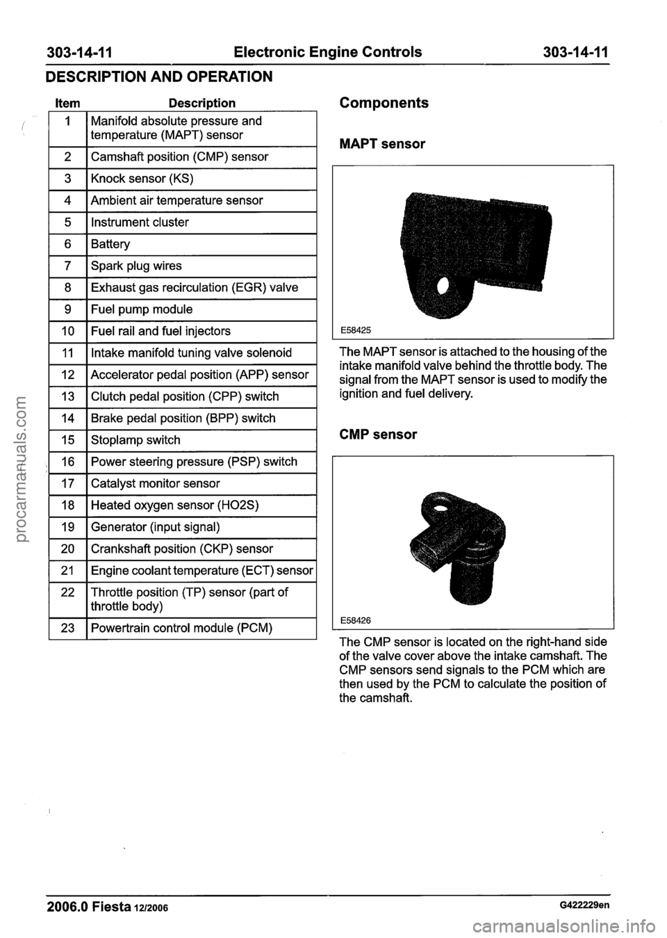
Item Description Components
MAPT sensor
Manifold absolute pressure and
temperature (MAPT) sensor
1 2 1 Camshaft position (CMP) sensor I
1 3 1 Knock sensor (KS) I
vl~Ame%air temperature sensor I
1 5 1 Instrument cluster I
1 6 1 Battery I
1 7 1 Spark plug wires I
1 8 1 Exhaust gas recirculation (EGR) valve I
1 9 1 Fuel pump module I
1 10 1 Fuel rail and fuel injectors I
I 11 I Intake manifold tuning valve solenoid The
MAPT sensor is attached to the housing of the
intake manifold valve behind the throttle body. The
signal from the MAPT sensor is used to modify the
ignition and fuel delivery.
1 12 1 Accelerator pedal position (APP) sensor
1 13 1 Clutch pedal position (CPP) switch
1 14 1 Brake pedal position (BPP) switch
CMP sensor 1 15 1 Stoplamp switch
1 16 1 Power steering pressure (PSP) switch I
1 17 1 Catalyst monitor sensor I
FIGted oxygen sensor (H02S) I
1 19 1 Generator (input signal) I
1 20 1 Crankshaft position (CKP) sensor I
1 21 1 Engine coolant temperature (ECT) sensor I
22 Throttle position
(TP) sensor (part of
I I throttle body)
1 23 1 Powertrain control module (PCM) I The CMP sensor is located on the right-hand side
of the valve cover above the intake camshaft. The
CMP sensors send signals to the PCM which are
then used by the PCM to calculate the position of
the camshaft.
2006.0 Fiesta 1212006 G422229en
procarmanuals.com
Page 936 of 1226
303-1 4-1 2 Electronic Engine Controls 303-1 4-1 2
DESCRIPTION AND OPERATION
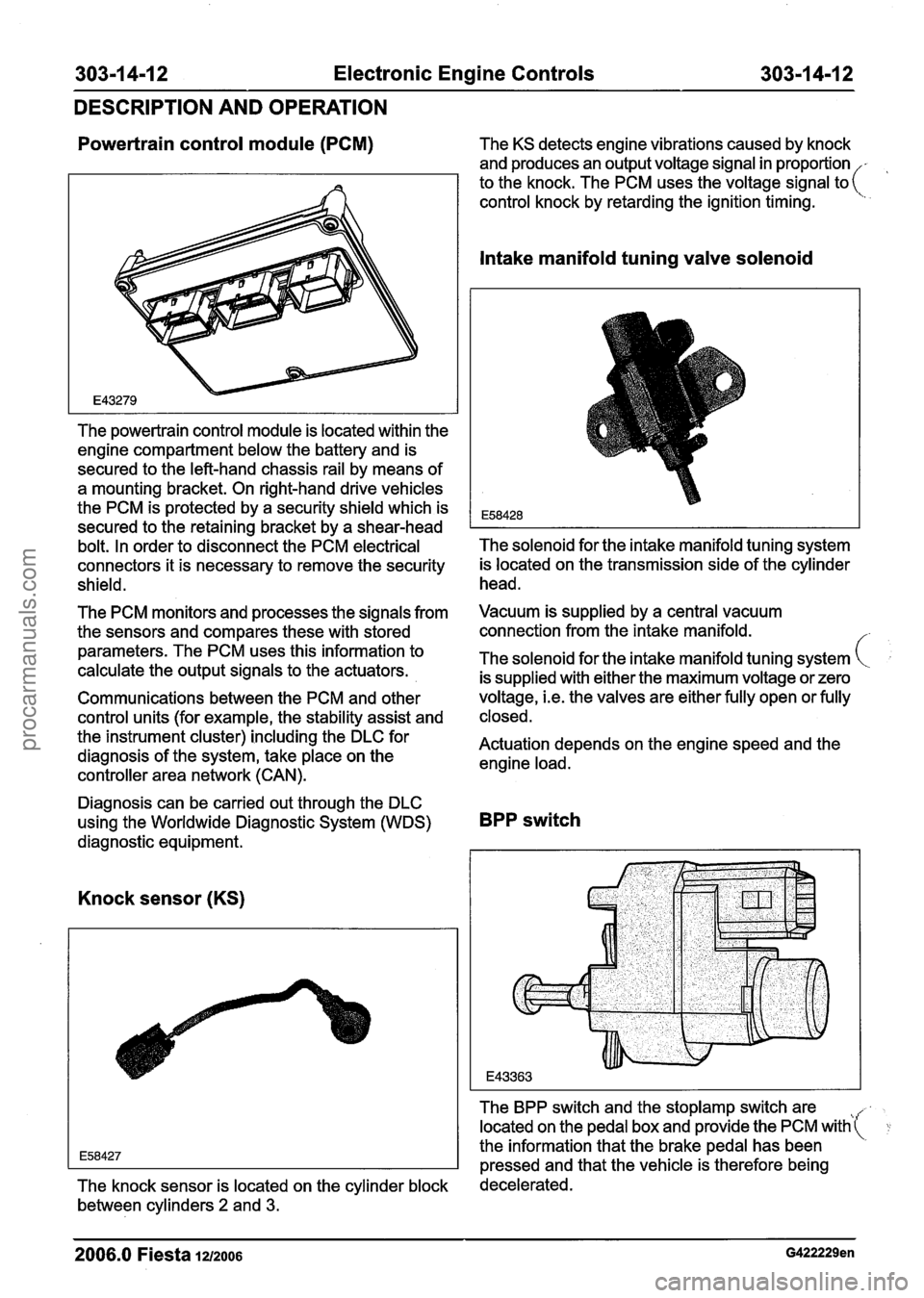
Powertrain control module (PCM) The KS detects engine vibrations caused by knock
and produces an output voltage signal in proportion
, to the knock. The PCM uses the voltage signal to(
control knock by retarding the ignition timing.
The powertrain control module is located within the
engine compartment below the battery and is
secured to the left-hand chassis rail by means of
a mounting bracket. On right-hand drive vehicles
the PCM is protected by a security shield which is
secured to the retaining bracket by a shear-head
bolt. In order to disconnect the PCM electrical
connectors it is necessary to remove the security
shield.
The PCM monitors and processes the signals from
the sensors and compares these with stored
parameters. The PCM uses this information to
calculate the output signals to the actuators.
Communications between the PCM and other
control units (for example, the stability assist and
the instrument cluster) including the DLC for
diagnosis of the system, take place on the
controller area network (CAN).
Intake manifold tuning valve solenoid
The solenoid for the intake manifold tuning system
is located on the transmission side of the cylinder
head.
Vacuum is supplied by a central vacuum
connection from the intake manifold.
The solenoid for the intake manifold tuning system
is supplied with either the maximum voltage or zero
voltage,
i.e. the valves are either fully open or fully
closed.
Actuation depends on the engine speed and the
engine load.
Diagnosis can be carried out through the DLC
using the Worldwide Diagnostic System (WDS)
BPP switch
diagnostic equipment.
Knock sensor (KS)
The BPP switch and the stoplamp switch are tt(r located on the pedal box and provide the PCM with
the information that the brake pedal has been
pressed and that the vehicle is therefore being
The knock sensor is located on the cylinder block decelerated.
between cylinders
2 and 3.
2006.0 Fiesta 1212006 G422229en
procarmanuals.com
Page 937 of 1226
303-1 4-1 3 Electronic Engine Controls 303-1 4-1 3
DESCRIPTION AND OPERATION
The BPP switch is connected to the instrument
When the brake pedal is pressed again the engine
cluster via a CAN bus. In its rest state the switch
speed drops to idle speed. When the brake pedal
is closed and sends a ground signal to the PCM.
returns to its rest position the engine speed is
The signal from the BPP switch is used in the event increased again.
of failure of the APP sensor for the emergency
operating mode.
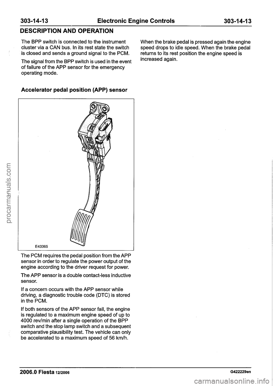
Accelerator pedal position (APP) sensor
The PCM requires the pedal position from the APP
sensor in order to regulate the power output of the
engine according to the driver request for power.
The APP sensor is a double contact-less inductive
sensor.
If a concern occurs with the APP sensor while
driving, a diagnostic trouble code
(DTC) is stored
in the PCM.
If both sensors of the APP sensor fail, the engine
is regulated to a maximum engine speed of up to
4000 revlmin after a single operation of the BPP
switch and the stop lamp switch and a subsequent
comparative plausibility test. The vehicle can only
be accelerated to a maximum speed of
56 kmlh.
2006.0 Fiesta 1212006 G422229en
procarmanuals.com
Page 940 of 1226
Electronic Engine Controls
DIAGNOSIS AND TESTING
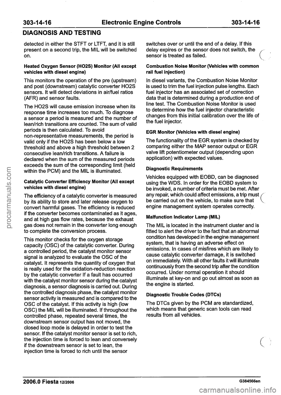
detected in either the STFT or LTFT, and it is still
present on a second trip, the MIL will be switched
on.
Heated Oxygen Sensor (H02S) Monitor (All except
vehicles with diesel engine)
This monitors the operation of the pre (upstream)
and post (downstream) catalytic converter
H02S
sensors. It will detect deviations in airlfuel ratios
(AFR) and sensor faults.
The
H02S will cause emission increase when its
response time increases too much. To diagnose
a sensor a period is measured and the number of
leanlrich transitions are counted. The sum of valid
periods is then calculated. To avoid
non-representative measurements, the period is
valid only if the
H02S has been below a low
threshold and above a high threshold between 2
consecutive leanlrich transitions.
A failure is
declared when the sum of the measured periods
exceeds the sum of the corresponding limit (held
within the PCM) and the MIL is illuminated.
Catalytic Converter Efficiency Monitor (All except
vehicles with diesel engine)
The efficiency of a catalytic converter is measured
by its ability to store and later release oxygen to
convert harmful gases. The efficiency is reduced
if the converter becomes contaminated as it ages,
and at high gas flow rates, because the exhaust
gas does not remain in the converter long enough
to complete the conversion process. switches
over or until the end of a delay. If this
delay expires or the sensor does not switch, the
sensor is treated as failed.
Combustion Noise Monitor (Vehicles with common
rail fuel injection)
In diesel variants, the Combustion Noise Monitor
is used to trim the fuel injection pulse lengths. Each
fuel injector has an associated set of correction
data that is determined during a production end of
line test. The Combustion Noise Monitor is used
to determine how the fuel injector characteristic
changes from this initial calibration over the life of
the fuel injector.
EGR Monitor (Vehicles with diesel engine)
The functionality of the EGR system is checked by
comparing either the MAP sensor output or EGR
valve lift potentiometer output (depending upon
application) with expected values.
Diagnostic Requirements
Vehicles equipped with EOBD, can be diagnosed
using the WDS. In order for the EOBD system to
be invoked, a number of criteria must be met. After
any repair, which could affect emissions, a trip must
be carried out on the vehicle, to make sure that
engine management system operates correctly.
Malfunction Indicator Lamp (MIL)
The MIL is located in the instrument cluster and is
fitted to alert the driver to the fact that an abnormal
This monitor checks for the oxygen storage condition
has developed in the engine management
capacity (OSC) of the catalytic converter. During system,
that is having an adverse effect on
a controlled period, the catalyst monitor sensor emissions.
In cases of misfires which are likely to
signal is analyzed to evaluate the OSC of the cause
catalytic converter damage, it is switched
catalyst. It represents the quantity of oxygen that on immediately.
With all other faults it will illuminate
is really used for the oxidation-reduction reaction continuously
from the second trip after the condition
by the catalytic converter If a fault has occurred occurred.
Under normal operation it should
with the catalyst monitor sensor during the catalyst illuminate
at key-on and go out almost as soon as
diagnosis, a sensor diagnosis is carried out. During the
engine is started.
the controlled diagnosis phase, the catalyst monitor
Diagnostic Trouble Codes (DTCs) sensor activity is measured and is compared to the
OSC of the catalyst. If this activity is high (low The
DTCs given
by the PCM are standardized,
0SC)theMILwillbeilluminated.Ifthroughoutthe whichmeansthatgenericscantoolscanread
controlled phase, repeated several times, the results from
all vehicles.
downstream sensor output has not moved, the
closed loop mode is delayed in order to test the
sensor. If the catalyst monitor sensor is set to rich,
the injection time is forced to lean and conversely
if the downstream sensor is set to lean, the
injection time is forced to rich until the sensor
2006.0 Fiesta 1212006 G384566en
procarmanuals.com
Page 943 of 1226
Electronic Engine Controls
DIAGNOSIS AND TESTING
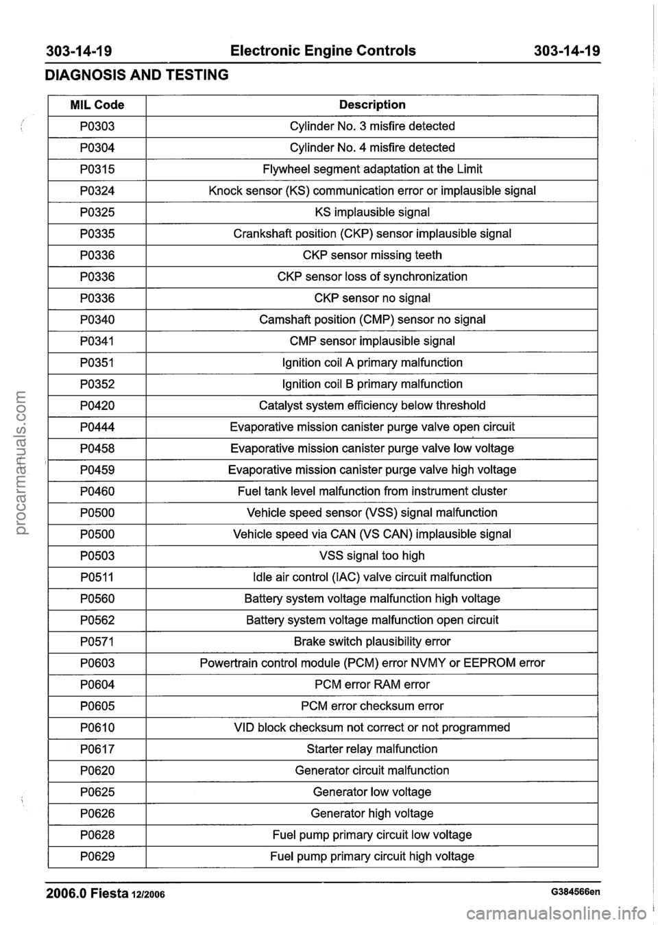
I PO304 I Cylinder No. 4 misfire detected I
/ I
KS implausible signal I
MIL Code
PO303
PO31 5
PO324
1 PO335 1 Crankshaft position (CKP) sensor implausible signal I
Description
Cylinder No. 3 misfire detected
Flywheel segment adaptation at the Limit
Knock sensor (KS) communication error or implausible signal
1 PO336 1 CKP sensor missing teeth I
1 PO336 1 CKP sensor loss of synchronization I
1 PO336 1 CKP sensor no signal I
I PO340 I Camshaft position (CMP) sensor no signal I
I PO341 I CMP sensor implausible signal I
I PO351 I Ignition coil A primary malfunction I
1 PO352 1 Ignition coil B primary malfunction I
I PO420 I Catalyst system efficiency below threshold I
1 PO444 1 Evaporative mission canister purge valve open circuit I
1 PO458 1 Evaporative mission canister purge valve low voltage I
I '1 PO459 1 Evaporative mission canister purge valve high voltage I
I PO460 I Fuel tank level malfunction from instrument cluster I
-3 I VSS signal too high I
PO500
PO500
Vehicle speed sensor (VSS) signal malfunction
Vehicle speed via CAN (VS CAN) implausible signal
PO51 1
PO560
I PO603 I Powertrain control module (PCM) error NVMY or EEPROM error 1
Idle air control (IAC) valve circuit malfunction
Battery system voltage malfunction high voltage
PO562
PO571
I PO604 I PCM error RAM error I
Battery system voltage malfunction open circuit
Brake switch plausibility error
PO605 I PCM error checksum error I
I PO610 I VID block checksum not correct or not programmed I
I PO617 I Starter relay malfunction I
I PO620 I Generator circuit malfunction I
1 PO628 1 Fuel pump primary circuit low voltage I
I
7 1 Fuel pump primary circuit high voltage I
2006.0 Fiesta 1212006 G384566en
PO625
PO626
Generator low voltage
Generator high voltage
procarmanuals.com
Page 989 of 1226
Automatic Transmission/Transaxle -
Vehicles With: 4-Speed Automatic
Transmission (AW81-40)
DESCRIPTION AND OPERATION
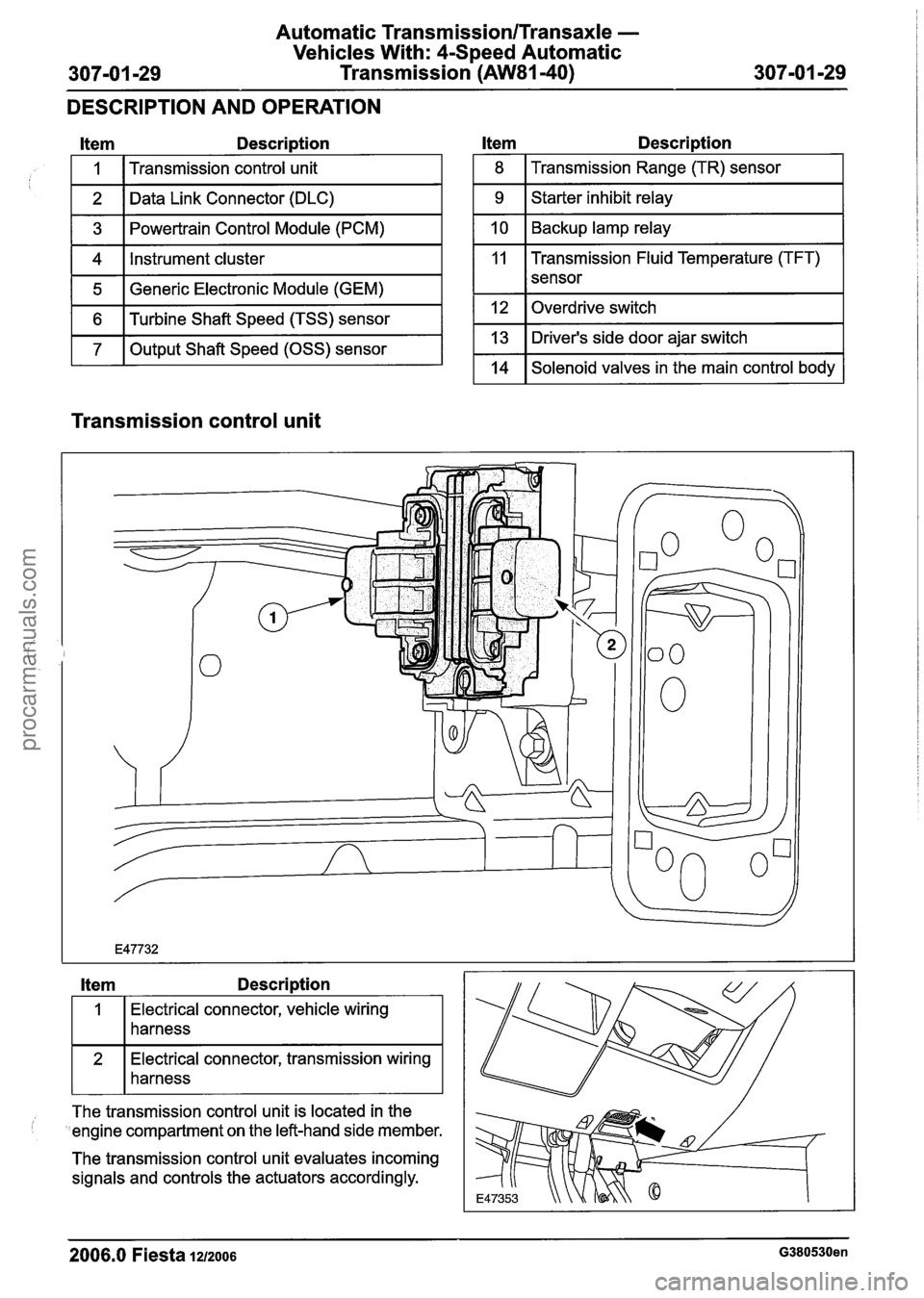
Item Description
1 5 1 Generic Electronic Module (GEM) I
I
1 6 1 Turbine Shaft Speed (TSS) sensor I
1 7 1 Output Shaft Speed (OSS) sensor I
1
2
3
4
l tem Description
Transmission control unit
Data Link Connector (DLC)
Powertrain Control Module (PCM)
Instrument cluster
1 8 I Transmission Range (TR) sensor I
1 9 1 Starter inhibit relay I
1 10 1 Backup lamp relay I
11 Transmission Fluid Temperature (TFT)
I I sensor
1 12 loverdrive switch I
1 13 1 Driver's side door ajar switch I
1 14 1 Solenoid valves in the main control body 1
Transmission control unit
Item Description
Electrical connector, vehicle wiring
harness
connector, transmission wiring
harness
--
The transmission control unit is located in the
'engine compartment on the left-hand side member.
The transmission control unit evaluates incoming
signals and controls the actuators accordingly.
2006.0 Fiesta 1212006 G380530en
procarmanuals.com
Page 994 of 1226
Automatic Transmission/Transaxle -
Vehicles With: 4Speed Automatic
307-01 -34 Transmission (AW81-40) 307-01 -34
DESCRIPTION AND OPERATION
Selector lever position "D" In selector lever position "2" engine braking is
effective when the vehicle is coasting.
In selector lever position
"D" the transmission
control will allow all gears to be engaged provided
the overdrive switch is not operated.
Selector lever position "1"
If the overdrive switch is pressed then the
Only the first gear is engaged when the selector
transmission control prevents gearshifts into 4th
lever is in position ,,. gear or shifts back into 3rd gear.
Selector lever position "2"
If the selector lever is moved to position "1" at
higher speeds than are permitted for first gear, then
the transmission control delays the downshift until
the vehicle speed has slowed down enough.
-
Only the second gear is engaged when the selector In selector lever position ,, engine braking is lever is in position "2". Gearshifts into 1st gear are effective when the vehicle is not permitted.
If the selector lever is moved to position
"2" at
higher speeds than are permitted for second gear,
then the transmission control delays the downshift until the vehicle speed has slowed down enough.
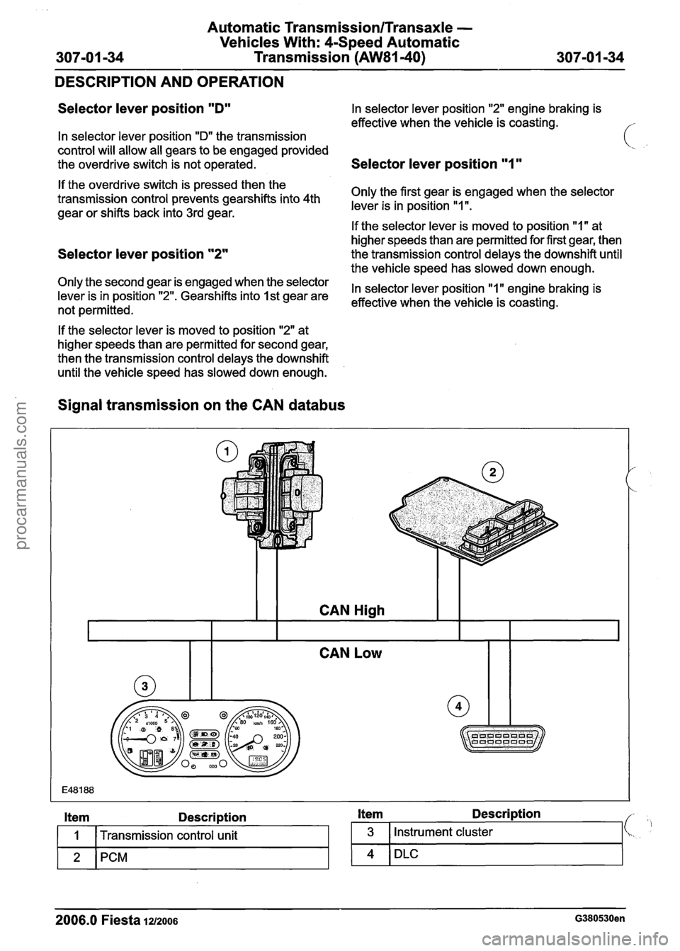
Signal transmission on the CAN databus
CAN Low
E48 1 88
Item Description Item Description
I 1 1 Transmission control unit 1 3 1 Instrument cluster
2006.0 Fiesta 1~2006 G380530en
2 PCM 4 DLC
procarmanuals.com
Page 995 of 1226
Automatic Transmission/Transaxle -
Vehicles With: 4Speed Automatic
307-01 -35 Transmission (AW81-40) 307-01 -35
DESCRIPTION AND OPERATION
Engine speed
1 The engine speed is detected by the crankshaft
position (CKP) sensor and passed on to the PCM.
The engine speed is transmitted from the PCM via
the CAN
databus to the transmission control unit.
The transmission control unit uses this signal for:
Torque reduction during gearshifts,
Pressure control during gearshifts.
Engine load
The PCM determines a load signal which is
transmitted via the CAN
databus to the
transmission control unit.
The transmission control unit uses this signal for:
Torque reduction during gearshifts,
Pressure control during gearshifts,
Shift timing adaptation during upshifts,
Shift timing adaptation during shifts from 3rd to
4th gear,
Hill climb mode,
( ' Hill descent mode. ' ,
Torque reduction request signal
Before performing a gearshift, the transmission
control unit sends a signal via the CAN
databus to
the PCM requesting a torque reduction.
The PCM then reduces the engine torque, ensuring
that the gearshift is as smooth and judder-free as
possible.
Brake signal
The PCM receives a signal from the stoplamp
switch when the brake pedal is depressed.
This signal is transmitted via the CAN
databus to
the transmission control unit.
The transmission control unit uses this signal for:
Gearshift control,
Engagement of the TCC
Accelerator pedal position
The PCM receives the current accelerator pedal
position signal from the Accelerator Pedal Position
(APP) sensor.
This signal is transmitted via the CAN
databus to
the transmission control unit.
The transmission control unit uses this signal for:
Controlling the main line pressure,
Gearshift control,
Engagement of the TCC,
Shift timing adaptation during upshifts,
Shift timing adaptation during shifts from 3rd to
4th gear,
Shift timing adaptation during shifts from 4th to
3rd gear,
Avoidance of gearshift judder during
engagement of a transmission range,
Torque reduction when pulling away.
Coolant temperature
The coolant temperature is detected by the Engine
Coolant Temperature (ECT) sensor and passed
on to the PCM.
This signal is transmitted via the CAN
databus to
the transmission control unit.
The transmission control unit uses this signal for:
Cold start mode,
Engagement of the TCC
Selector lever position
The transmission control unit transmits the selector
lever position to the instrument cluster.
The instrument cluster uses the signal to send a
request for a warning tone to the GEM when the
selector lever is not in position "P" and the driver's
door is opened.
-
2006.0 Fiesta 1212006 G380530en
procarmanuals.com
Page 996 of 1226
Automatic Transmission/Transaxle -
Vehicles With: 4-Speed Automatic
307-01 -36 Transmission (AW81-40) 307-01 -36
DESCRIPTION AND OPERATION
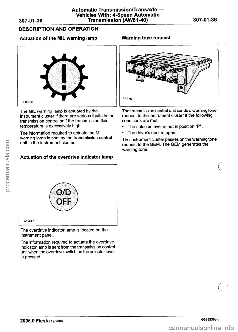
Actuation of the MIL warning lamp Warning tone request
The information required to actuate the
MIL The
driver's door is open.
warning lamp is sent the transmission control The instrument cluster passes on the warning tone unit to the instrument cluster.
request to the GEM. The GEM generates the
warning tone.
I I I
Actuation of the overdrive indicator lamp
I
The overdrive indicator lamp is located on the
instrument panel.
The MIL warning lamp
is actuated by the The transmission control unit sends
a warning tone
instrument cluster if there are serious faults in the request
to the instrument cluster if the following
transmission control or if the transmission fluid conditions are
met:
temperature is excessively high.
The selector lever is not in position "P",
The information required to actuate the overdrive
indicator lamp is sent from the transmission control
unit when the overdrive switch on the selector lever
is pressed.
2006.0 Fiesta 1u2oos G380530en
procarmanuals.com