instrument cluster FORD FIESTA 2007 Owner's Manual
[x] Cancel search | Manufacturer: FORD, Model Year: 2007, Model line: FIESTA, Model: FORD FIESTA 2007Pages: 1226, PDF Size: 61.26 MB
Page 999 of 1226

Automatic Transmission/Transaxle -
Vehicles With: 4-Speed Automatic
307-01 -39 Transmission (AW81-40) 307-01 -39
DESCRIPTION AND OPERATION
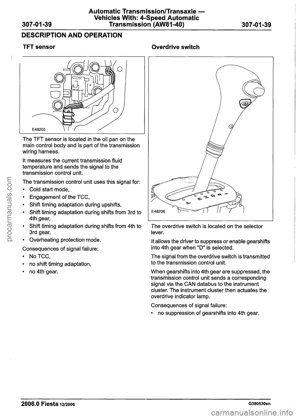
TFT sensor Overdrive switch
The TFT sensor is located in the oil pan on the
main control body and is part of the transmission
wiring harness.
It measures the current transmission fluid
temperature and sends the signal to the
transmission control unit.
The transmission control unit uses this signal for:
Cold start mode,
Engagement of the TCC,
Shift timing adaptation during upshifts,
' , Shift timing adaptation during shifts from 3rd to
4th gear,
Shift timing adaptation during shifts from 4th to
3rd gear,
Overheating protection mode.
Consequences of signal failure:
NoTCC,
no shift timing adaptation,
no 4th gear. The overdrive switch
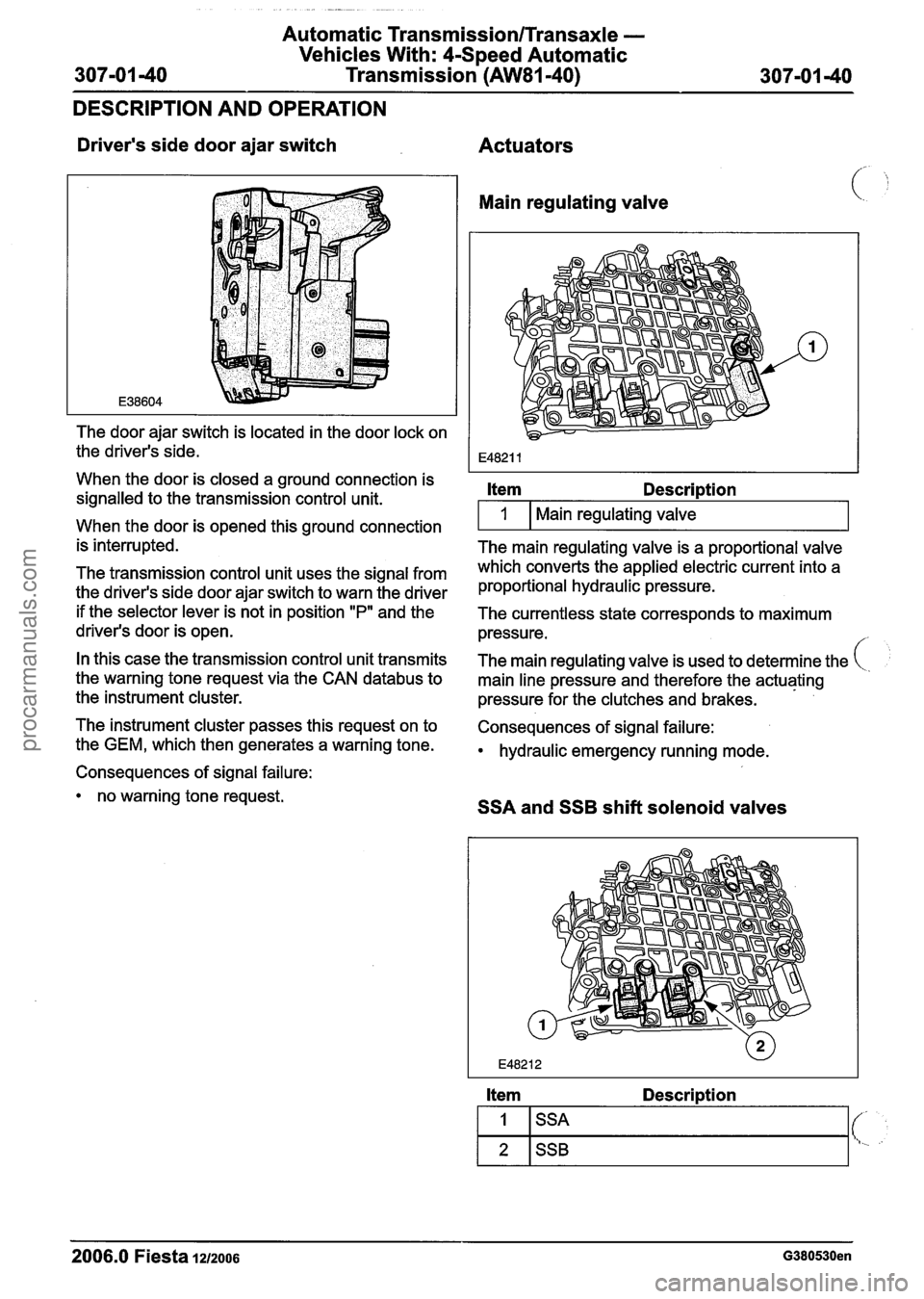
is located on the selector
lever.
It allows the driver to suppress or enable gearshifts
into 4th gear when
"D" is selected.
The signal from the overdrive switch is transmitted
to the transmission control unit.
When gearshifts into 4th gear are suppressed, the
transmission control unit sends a corresponding
signal via the CAN
databus to the instrument
cluster. The instrument cluster then actuates the
overdrive indicator lamp.
Consequences of signal failure:
no suppression of gearshifts into 4th gear.
2006.0 Fiesta 1212006 G380530en
procarmanuals.com
Page 1000 of 1226

Automatic Transmission/Transaxle -
Vehicles With: 4-Speed Automatic
307-01 -40 Transmission (AW81-40)
307-01 -40
DESCRIPTION AND
OPEMION
Driver's side door ajar switch
The door ajar switch is located in the door lock on
the driver's side.
When the door is closed a ground connection is
signalled to the transmission control unit.
When the door is opened this ground connection
is interrupted.
The transmission control unit uses the signal from
the driver's side door ajar switch to warn the driver
if the selector lever is not in position
"P" and the
driver's door is open.
In this case the transmission control unit transmits
the warning tone request via the CAN
databus to
the instrument cluster.
The instrument cluster passes this request on to
the GEM, which then generates a warning tone.
Consequences of signal failure:
no warning tone request.
Actuators
Main regulating valve
Item Description
I 1 I Main regulating valve I
The main regulating valve is a proportional valve
which converts the applied electric current into a
proportional hydraulic pressure.
The currentless state corresponds to maximum
pressure.
/
The main regulating valve is used to determine the
main line pressure and therefore the actuating
pressure for the clutches and brakes.
Consequences of signal failure:
hydraulic emergency running mode.
SSA and SSB shift solenoid valves
Item Description
2006.0 Fiesta 1212006 G380530en
1
2
SSA
SSB
(- t..
procarmanuals.com
Page 1225 of 1226

31 0-02B-3 Acceleration Control - 2.OL Duratec-HE (M14) 31 0-02B-3
DESCRIPTION AND OPERATION
position from the throttle position (TP) sensors to
make sure that the requested position has been
lachieved .
N0TE:Do not install a new accelerator pedal
unless a relevant accelerator pedal DTC has been
stored in the PCM. For additional information refer
to WDS.
The accelerator pedal is a non-serviceable
component which cannot be adjusted and therefore
must not be disassembled or tampered with.
The throttle body is directly controlled by the PCM
and has two TP sensors, TP
1 and TP 2. The TP
sensors output a voltage to the PCM that
corresponds to the actual throttle plate position.
When the throttle body motor is not being powered
up, the throttle plate sits open at approximately 8
degrees from the closed in-bore position. This
position (also referred to as the default position),
is maintained within the throttle body by two internal
compression return springs acting in opposing
directions, these springs are a non-serviceable
item.
The PCM continuously monitors both APP sensors
and both TP sensors to make sure that the system
,is functioning as expected. All acceleration control
( 'system concerns will be detected by the PCM and
the appropriate diagnostic trouble code (DTC) set.
The malfunction indicator lamp (MIL), located in
the instrument cluster will also be illuminated if a
concern is apparent. As the acceleration control
system is of a safety-critical nature, it is possible
that a system concern will result in a reduced
vehicle performance and a DTC stored in the PCM.
For additional information refer to WDS.
2006.0 Fiesta 1212006 G422706en
procarmanuals.com