drain bolt FORD FIESTA 2007 Owner's Manual
[x] Cancel search | Manufacturer: FORD, Model Year: 2007, Model line: FIESTA, Model: FORD FIESTA 2007Pages: 1226, PDF Size: 61.26 MB
Page 763 of 1226
Engine Cooling - 1.3L Duratec-8V
(Rocam)ll.25L Duratec-1 6V (Sigma)ll.4L
303-03A-21 Duratec-1 6V (Sigma)/l .6L Duratec-1 6V (Sigma) 303-03A-21
REMOVAL AND INSTALLATION
Water Pump - 1.25L Duratec-1 6V (Sigma)/l.4L Duratec-1 6V
(Sigma)/l .6L Duratec-1 6V (Sigma)(24 404 0)
Removal
Vehicles built up to 0412005
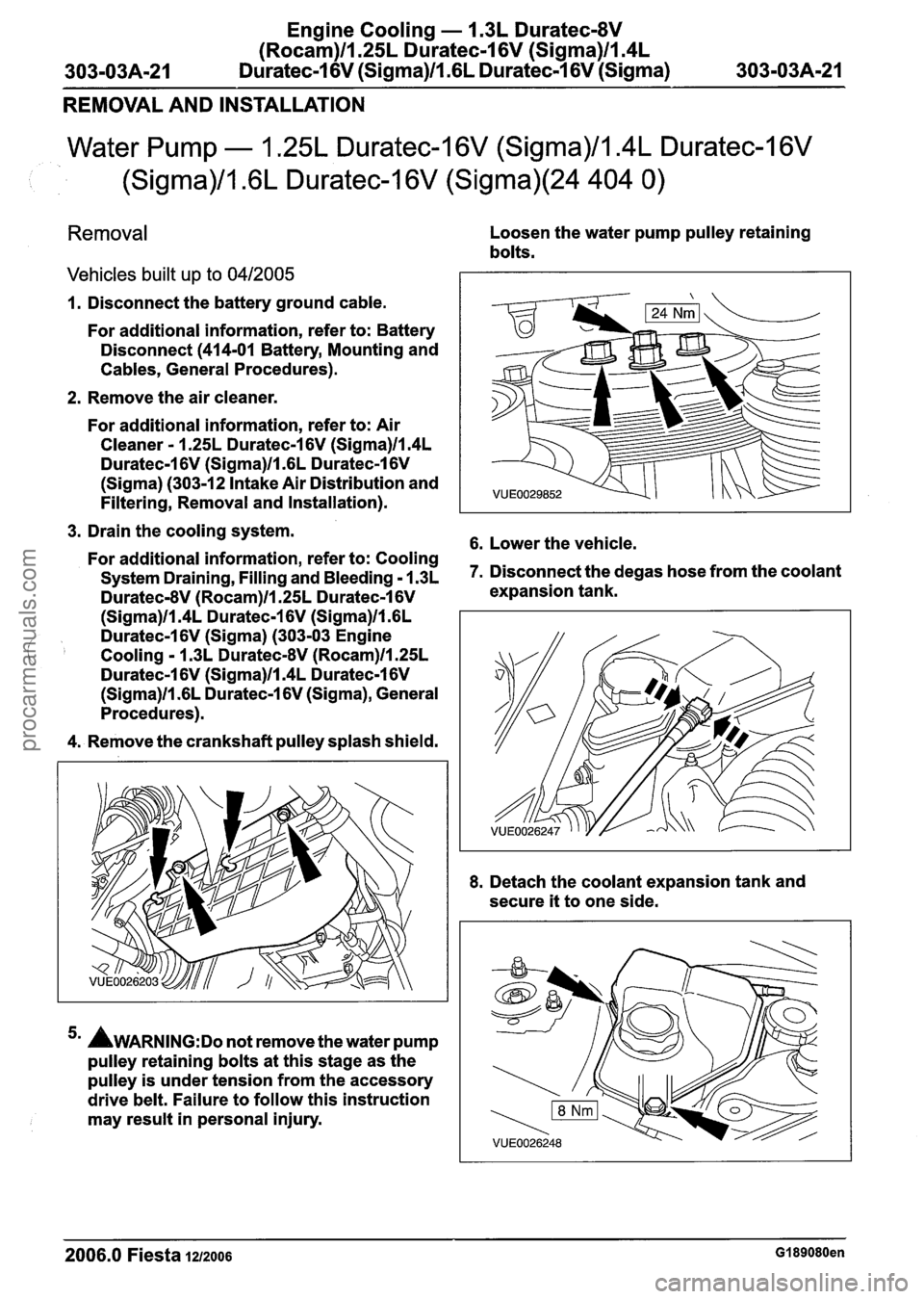
Loosen the water pump pulley retaining
bolts.
1. Disconnect the battery ground cable.
For additional information, refer to: Battery
Disconnect
(414-01 Battery, Mounting and
Cables, General Procedures).
2. Remove the air
cleaner.
For additional information, refer to: Air
Cleaner - 1.25L Duratec-1 6V (Sigma)ll.4L
Duratec-1 6V (Sigma)ll .6L Duratec-1 6V
(Sigma) (303-12 Intake Air Distribution and
Filtering, Removal and Installation).
3. Drain the cooling system.
6. Lower the vehicle. For additional information, refer to: Cooling
System Draining, Filling and Bleeding - 1.3~ 7. Disconnect the degas hose from the coolant
Duratec-8V (Rocam)ll.25L Duratec-1 6V expansion tank.
(Sigma)ll.4L Duratec-1 6V (Sigma)ll .6L
Duratec-1 6V (Sigma) (303-03 Engine
Cooling - 1.3L DuratecdV (Rocam)ll.25L
Duratec-1 6V (Sigma)ll.4L Duratec-1 6V
(Sigma)ll .6L Duratec-1 6V (Sigma), General
Procedures).
4. Remove the crankshaft
pulley splash shield.
5m AWARNING:D~ not remove the water pump
pulley retaining bolts at this stage as the
pulley is under tension from the accessory
drive
belt. Failure to follow this instruction
may
result in personal injury. 8.
Detach the
coolant expansion tank and
secure
it to one side.
2006.0 Fiesta 1212006 GI 89080en
procarmanuals.com
Page 789 of 1226
303-03B-19 Engine Cooling - 2.OL Duratec-HE (M14) 303-03B-19
REMOVAL AND INSTALLATION
Coolant Pump(24 404 0)
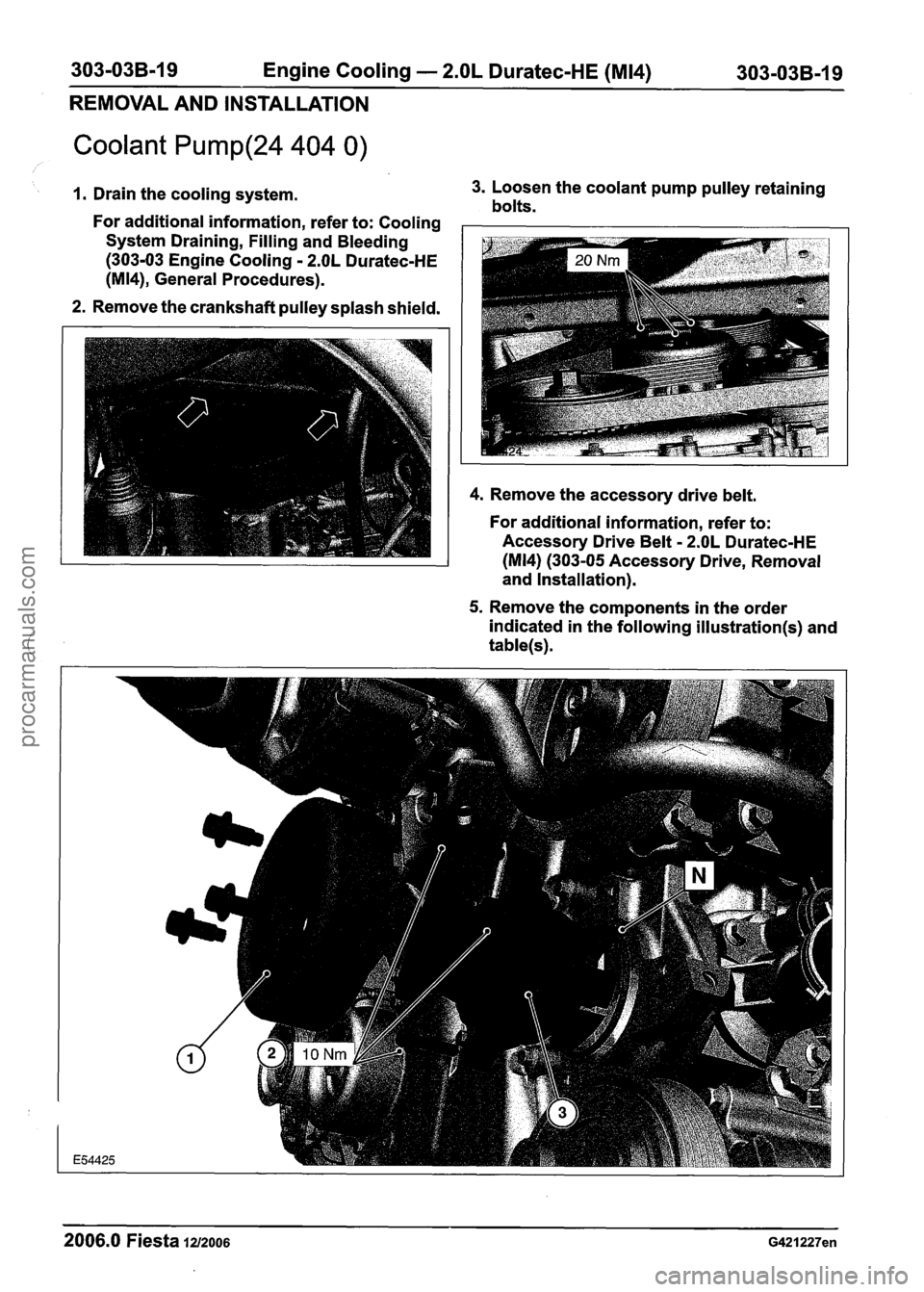
1. Drain the cooling system. 3.
Loosen the coolant pump pulley retaining bolts. - - - - - - -
For additional information, refer to: Cooling -
System Draining, Filling and Bleeding
(303-03 Engine Cooling - 2.OL Duratec-HE
(M14), General Procedures).
2. Remove the crankshaft pulley splash shield.
4. Remove the accessory drive belt.
For additional information, refer to:
Accessory Drive Belt
- 2.OL Duratec-HE
(M 14) (303-05 Accessory Drive, Removal
and Installation).
5. Remove the components in the order
indicated in the following
illustration(s) and
table(s).
2006.0 Fiesta 1212006 G421227en
procarmanuals.com
Page 963 of 1226
Automatic TransmissionlTransaxle -
Vehicles With: 4-Speed Automatic
Transmission
(AW81-40)
SPECIFICATIONS
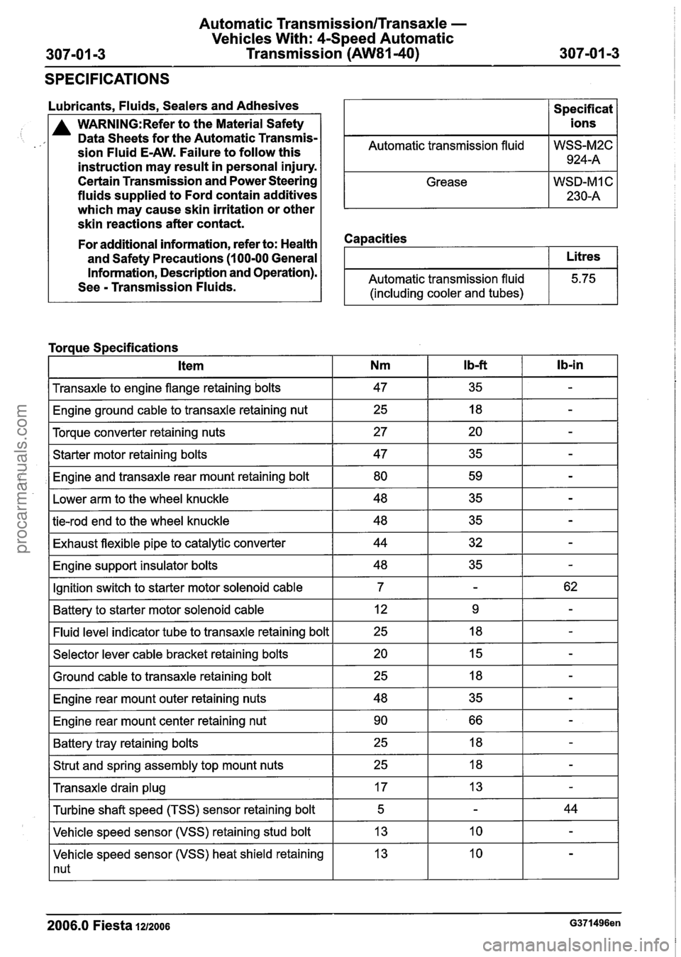
Lubricants, Fluids, Sealers and Adhesives
A WARN1NG:Refer to the Material Safety
Data Sheets for the Automatic Transmis-
sion Fluid E-AW. Failure to follow this
instruction may result in personal injury.
Certain Transmission and Power Steering
fluids supplied to Ford contain additives
which may cause skin irritation or other
skin reactions after contact.
Automatic transmission fluid
Grease
Capacities
Specif icat
ions
WSS-M2C 924-A
WSD-MI C
230-A
For additional information, refer to: Health
and Safety Precautions
(1 00-00 General
Information, Description and Operation).
See
- Transmission Fluids. Automatic transmission fluid
(including cooler and tubes)
I Transaxle to engine flange retaining bolts I 47 I 35 I - I
Litres
5.75
Torque Specifications
I Engine ground cable to transaxle retaining nut I 25 I 18 I - I
I Torque converter retaining nuts I 27 I 20 I - I
lb-in Item
I Starter motor retaining bolts I 47 I 35 I - I
,I Engine and transaxle rear mount retaining bolt I 80 I 59 I - I
Nm
I Lower arm to the wheel knuckle I 48 I 35 I - I
I b-ft
I tie-rod end to the wheel knuckle I 48 I 35 I - I
I Exhaust flexible pipe to catalytic converter I 44 I 32 I - I
I Engine support insulator bolts I 48 I 35 I - I
IGnition switch to starter motor solenoid cable I 7 I - I 62 I
I Battery to starter motor solenoid cable I 12 I 9 I - I
-I indicator tube to transaxle retaining bolt I 25 I 18 I - I
I Selector lever cable bracket retaining bolts I 20 I 15 I - I - -
I Ground cable to transaxle retaining bolt
I Engine rear mount outer retaining nuts
I Engine rear mount center retaining nut I 90 I 66 I - I
I Battery tray retaining bolts I 25 I 18 I - I
I Strut and spring assembly top mount nuts I 25 I 18 I - I - -
Transaxle drain plug
Vehicle speed sensor (VSS) heat shield retaining
1 nut
Turbine
shaft speed (TSS) sensor retaining bolt
Vehicle speed sensor (VSS) retaining stud bolt
2006.0 Fiesta 1212006 G371496en
17
5
13 13 -
-
10
44
-
procarmanuals.com
Page 1061 of 1226
Manual Transmission/Transaxle and Clutch -
308-00-3 General Information 308-00-3
DIAGNOSIS AND TESTING
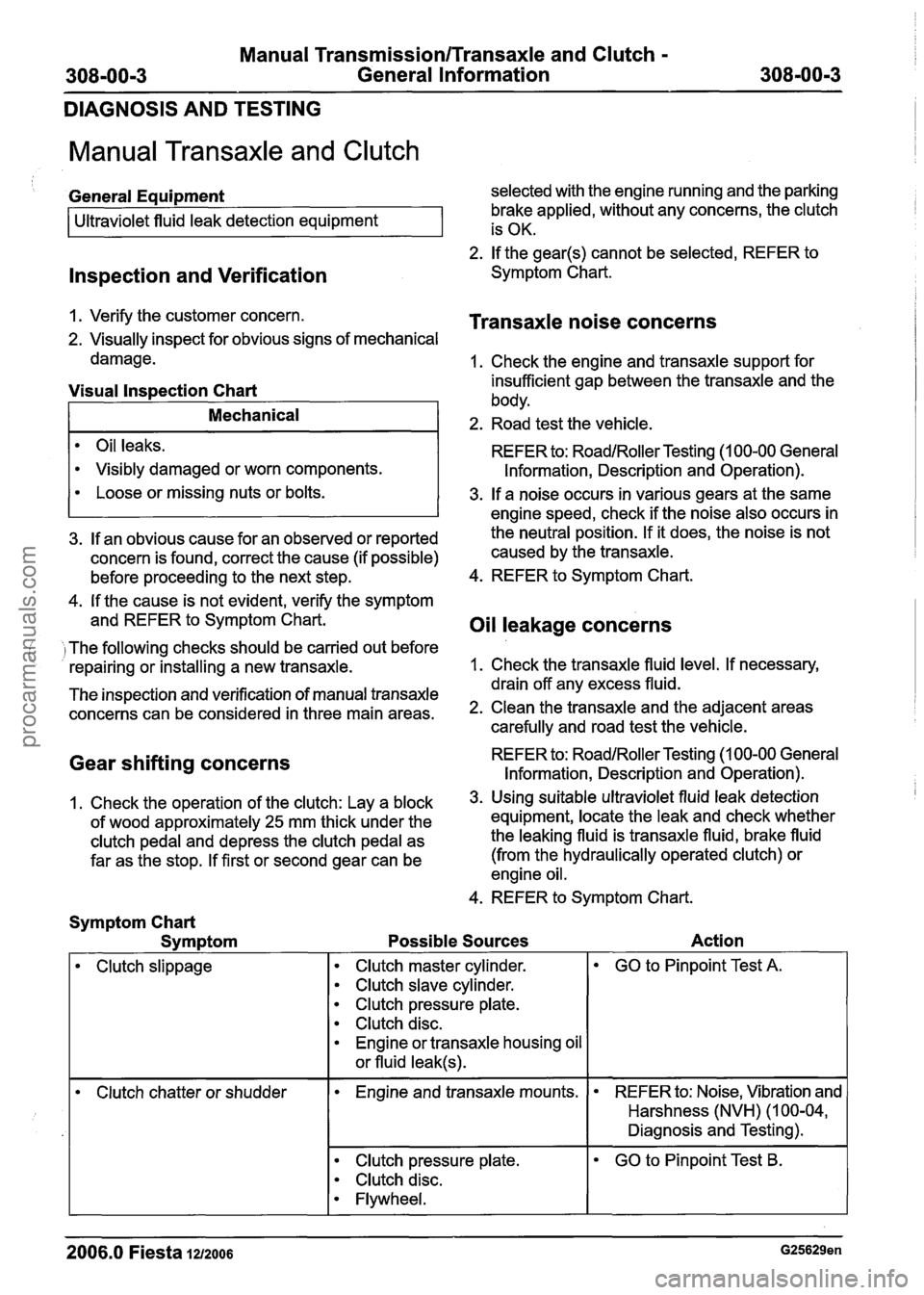
Manual Transaxle and Clutch
lnspection and Verification
General Equipment selected with the engine running and the parking
brake applied, without any concerns, the clutch
2. If the gear@) cannot be selected, REFER to
Symptom Chart.
Ultraviolet
fluid leak detection equipment
1. Verify the customer concern.
Transaxle noise concerns
2. Visually inspect for obvious signs of mechanical is
OK.
damage. 1. Check the engine and transaxle support for
Oil leaks.
Visibly damaged or worn components.
Visual lnspection Chart insufficient gap between the transaxle and the
body.
REFER to:
RoadlRoller Testing (1 00-00 General
Information, Description and Operation).
Mechanical 2. Road test the vehicle.
4. If the cause is not evident, verify the symptom
and REFER to Symptom Chart.
Oil leakage concerns
Loose or missing nuts or bolts.
( I The following checks should be carried out before
repairing or installing a new transaxle. 1.
Check the transaxle fluid level. If necessary,
3. If a noise occurs in various gears at the same
- - drain off any excess fluid.
The inspection and verification of manual transaxle
concerns can be considered in three main areas. 2. Clean the transaxle and the adjacent areas
carefully and road test the vehicle.
engine speed,
check if the noise also occurs in
3. If an obvious cause for an observed or reported the neutral position.
If it does, the noise is not
concern is found, correct the cause (if possible) caused
by the transaxle.
before proceeding to the next step. 4.
REFER to Symptom Chart.
Gear shifting concerns REFER to: RoadlRoller Testing (1 00-00 General
Information, Description and Operation).
1, Check the operation of the clutch: Lay a block 3. U~ing suitable ultraviolet fluid leak detection
of wood approximately
25 mm thick under the equipment, locate
the leak and check whether
clutch pedal and depress the clutch pedal as the leaking fluid
is transaxle fluid, brake fluid
far as the stop. If first or second gear can be (from the hydraulically operated clutch)
or
engine oil.
4. REFER to Symptom Chart.
Symptom Chart
Symptom Possible Sources Action
I
Clutch slippage Clutch master
cylinder.
Clutch slave cylinder.
Clutch pressure plate.
Clutch disc.
Engine or transaxle housing oil
or fluid
leak@).
GO to Pinpoint Test A.
Clutch chatter or shudder Engine and transaxle
mounts. REFER to:
Noise, Vibration and
Harshness (NVH) (1 00-04,
Diagnosis and Testing).
Clutch pressure plate.
Clutch disc.
Flywheel.
--
GO to Pinpoint Test B.
- -
2006.0 Fiesta 1212006 G25629en
procarmanuals.com
Page 1210 of 1226
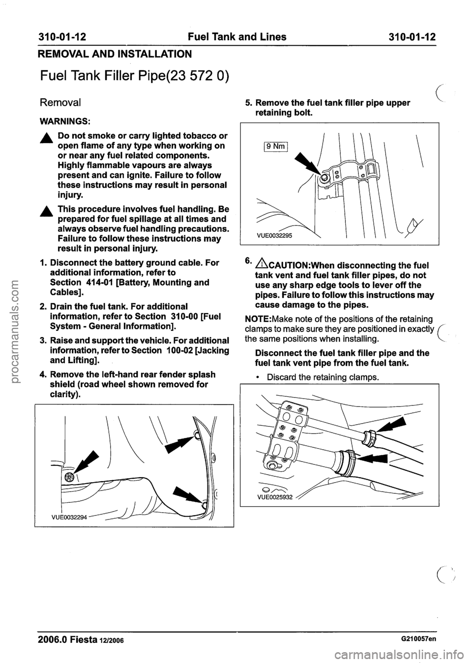
31 0-01 -1 2 Fuel Tank and Lines 31 0-01-12
REMOVAL AND INSTALLATION
Fuel Tank Filler Pipe(23 572 0)
Removal
WARNINGS:
A Do not smoke or carry lighted tobacco or
open flame of any type when working on
or near any fuel related components.
Highly flammable vapours are always
present and can ignite. Failure to follow
these instructions may result in personal
injury.
A This procedure involves fuel handling. Be
prepared for fuel spillage at all times and
always observe fuel handling precautions.
Failure to follow these instructions may
result in personal injury.
I. Disconnect the battery ground cable. For
additional information, refer to
Section
41 4-01 [Battery, Mounting and
Cables].
2. Drain the fuel tank. For additional
information, refer to Section
31 0-00 [Fuel
System
- General Information].
3. Raise and support the vehicle. For additional
information, refer to Section
100-02 [Jacking
and Lifting].
4. Remove the left-hand rear fender splash
shield (road wheel shown removed for
clarity).
5. Remove the fuel tank filler pipe upper (.
retaining bolt.
'' &AUTION:W~~~ disconnecting the fuel
tank vent and fuel tank filler pipes, do not
use any sharp edge tools to lever off the
pipes. Failure to follow this instructions may
cause damage to the pipes.
N0TE:Make note of the positions of the retaining
clamps to make sure they are positioned in exactly
the same positions when installing.
Disconnect the fuel tank filler pipe and the
fuel tank vent pipe from the fuel tank.
Discard the retaining clamps.
2006.0 Fiesta 1212006 G210057en
procarmanuals.com