timing FORD FIESTA 2007 Service Manual
[x] Cancel search | Manufacturer: FORD, Model Year: 2007, Model line: FIESTA, Model: FORD FIESTA 2007Pages: 1226, PDF Size: 61.26 MB
Page 595 of 1226
Engine - 1.25L Duratec-1 6V (Sigma)llm4L
303-OIA-119 Duratec-1 6V (Sigma)llI6L Duratec-1 6V (Sigma) 303-01 A-1 19
ASSEMBLY
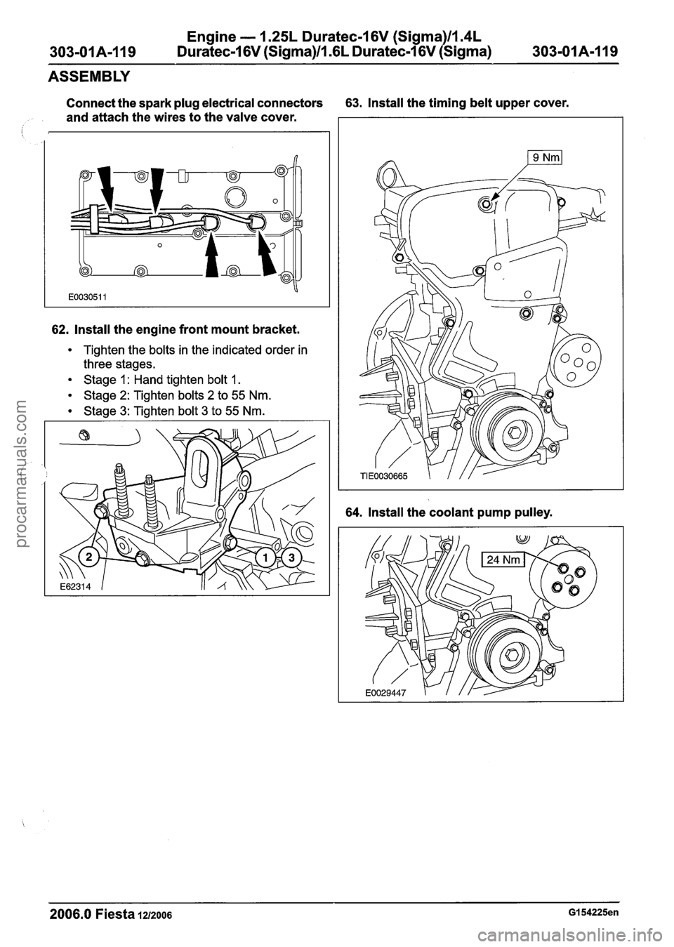
Connect the spark plug electrical connectors 63. Install the timing belt upper cover.
and attach the wires to the valve cover.
I
62. Install the engine front mount bracket.
Tighten the bolts in the indicated order in
three stages.
Stage 1 : Hand tighten bolt 1.
Stage 2: Tighten bolts 2 to 55 Nm.
Stage 3: Tighten bolt 3 to 55 Nm.
64. Install the coolant pump pulley.
2006.0 Fiesta 1~1zoo6 GI 54225en
procarmanuals.com
Page 623 of 1226
303-01 B-I Engine -- 2.OL Duratec-HE (M14) 303-01 B-1
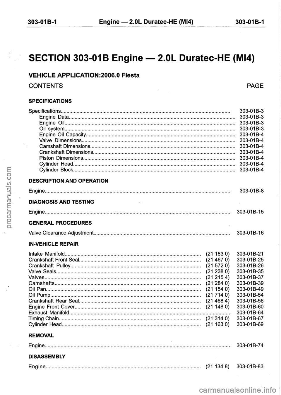
SECTION 303-01 B Engine . 2.OL Duratec-HE (M14)
VEHICLE APPLICATION:2006.0 Fiesta
CONTENTS
SPECIFICATIONS
........................................................................\
.............................................. Specifications
Engine Data
........................................................................\
............................................
Engine Oil ........................................................................\
...............................................
........................................................................\
............................................... Oil system
Engine Oil Capacity
........................................................................\
................................
Valve Dimensions ........................................................................\
...................................
Camshaft Dimensions ........................................................................\
.............................
Crankshaft Dimensions ........................................................................\
...........................
Piston Dimensions ........................................................................\
..................................
Cylinder Head ........................................................................\
.........................................
Cylinder Block ........................................................................\
.........................................
PAGE
DESCRIPTION AND OPERATION
Engine ........................................................................\
......................................................... 303-01 8-8
DIAGNOSIS AND TESTING
Engine ........................................................................\
.........................................................
GENERAL PROCEDURES
........................................................................\
....................... Valve Clearance Adjustment
IN-VEHICLE REPAIR
Intake Manifold ........................................................................\
................. (21 183 0)
Crankshaft Front Seal ........................................................................\
............. (21 467 0)
Crankshaft Pulley ........................................................................\
................... (21 5720)
Valve Seals ........................................................................\
....................... (21 238 0)
Valves ........................................................................\
................................. (21 2154)
Camshafts ........................................................................\
.......................... (21 284 0)
Oil Pan ........................................................................\
................................. (21 154 0)
Oil Pump ........................................................................\
.............................. (21 714 0)
Crankshaft Rear Seal ........................................................................\
.......... (21 468 4)
Engine Front Cover ........................................................................\
............. (21 148 0)
Exhaust Manifold ........................................................................\
........................................
Timing Chain ........................................................................\
........................ (21 314 0)
Cylinder Head ........................................................................\
....................... (21 163 0)
REMOVAL
Engine ........................................................................\
.........................................................
DISASSEMBLY
Engine ........................................................................\
................................ (21 134 8)
procarmanuals.com
Page 628 of 1226
,303-01 B-6 Engine - 2.OL Duratec-HE (M14) 303-01 B-6
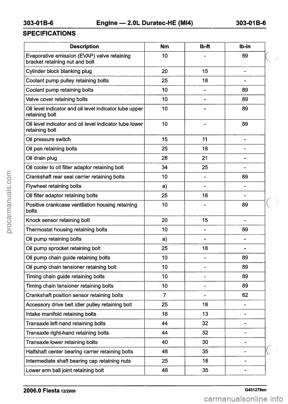
SPECIFICATIONS
I Description I Nm' I Ib-ft I Ib-in I
Evaporative emission (EVAP) valve retaining
bracket retaining nut and bolt
Valve cover retaining bolts
I 10 I - I 89 I
Cylinder block blanking plug
Coolant pump pulley retaining bolts
Coolant pump retaining bolts
Oil level indicator and oil level indicator tube upper
retaining bolt
Oil level indicator and oil level indicator tube lower
retaining bolt 20
25
10
Oil pressure switch I 15 I 11 I - I
I Oil pan retaining bolts
15
18
-
-
-
89
I Crankshaft rear seal carrier retaining bolts I 10 I - I 89 I
Oil drain plug
Oil cooler to oil filter adaptor retaining bolt
I Flywheel retaining bolts I a) I - I - I
28
34
I Knock sensor retaining bolt I 20 I 15 I - I
Oil filter adaptor retaining bolts
Positive crankcase ventilation housing retaining
bolts
I Thermostat housing retaining bolts I 10 I - I 89 I
21
25
I Oil pump retaining bolts I a) I - I - I
-
-
25
10
I Oil pump sprocket retaining bolt I 25 I 18 I - I
18
-
-
89
Oil pump chain guide retaining bolts
Oil pump chain tensioner retaining bolt
I Crankshaft position sensor retaining bolts I 7 I - I 62 I
Timing chain guide retaining bolts
Timing chain tensioner retaining bolts
I Accessory drive belt idler pulley retaining bolt I 25 I 18 I - I
10
10
I Intake manifold retaining bolts I 18 I 13 I - I
10
10
I Transaxle left-hand retaining bolts I 44 I 32 I - I
-
-
I Transaxle right-hand retaining bolts I 44 I 32 I - I
89
89
-
-
89
89
Transaxle lower retaining bolts
Halfshaft center bearing carrier retaining bolts
I Lower arm ball joint retaining bolt I 48 I 35 I - I
Intermediate shaft bearing cap retaining nuts
2006.0 Fiesta 1212006 G451278en
40
48
25 30
35 -
-
18 -
procarmanuals.com
Page 632 of 1226
303-01 B-I 0 Engine - 2.OL Duratec-HE (M14) 303-01 B-I 0 - -- --
DESCRIPTION AND OPERATION
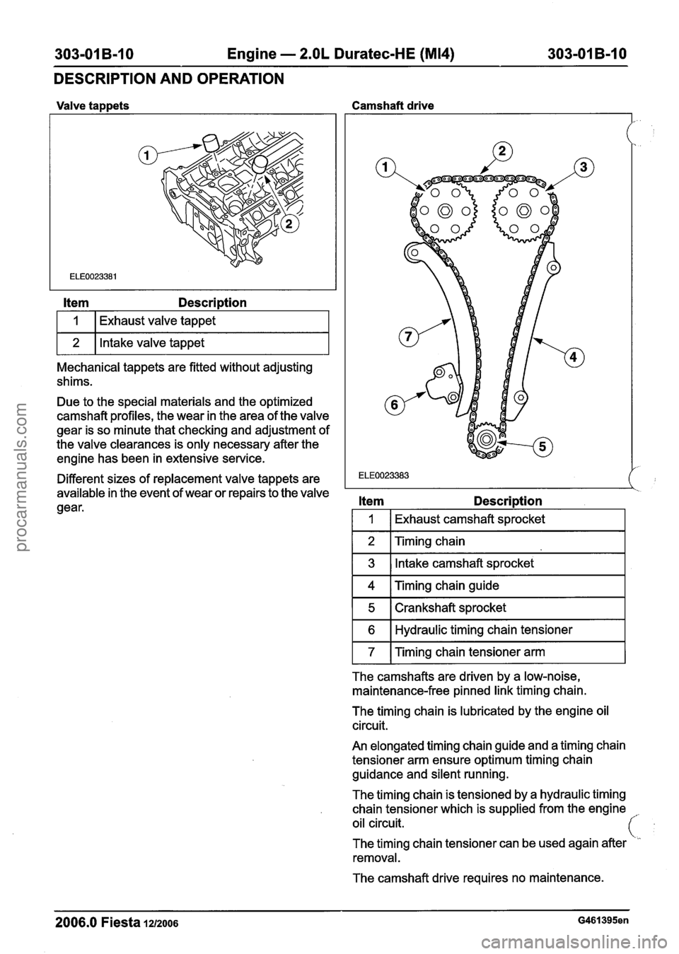
Valve tappets Camshaft drive
Item Description
I 1 I Exhaust valve tappet I
1 2 1 Intake valve tappet I
Mechanical tappets are fitted without adjusting
shims.
Due to the special materials and the optimized
camshaft profiles, the wear in the area of the valve
gear is so minute that checking and adjustment of
the valve clearances is only necessary after the
engine has been in extensive service.
Different sizes of replacement valve tappets are
I ELE0023383
available in the event of wear or repairs to the valve ' '2
gear. Item Description
I 1 I Exhaust camshaft sprocket
1 2 I Timing chain I
1 3 1 Intake camshaft sprocket I
1 4 I ~imin~ chain guide I
1 5 1 Crankshaft sprocket I
1 6 1 Hydraulic timing chain tensioner I
1 7 1 ~imin~ chain tensioner arm 1 - -
The camshafts are driven by a low-noise,
maintenance-free pinned link timing chain.
The timing chain is lubricated by the engine oil
circuit.
An elongated timing chain guide and a timing chain
tensioner arm ensure optimum timing chain
guidance and silent running.
The timing chain is tensioned by a hydraulic timing
chain tensioner which is supplied from the engine
,.
oil circuit.
The timing chain tensioner can be used again after
removal.
The camshaft drive requires no maintenance.
2006.0 Fiesta 1212006 G461395en
procarmanuals.com
Page 648 of 1226
303-01 B-26 Engine - 2.OL Duratec-HE (M14) 303-01 B-26
IN-VEHICLE REPAIR
Crankshaft Pulley(21 572 0)
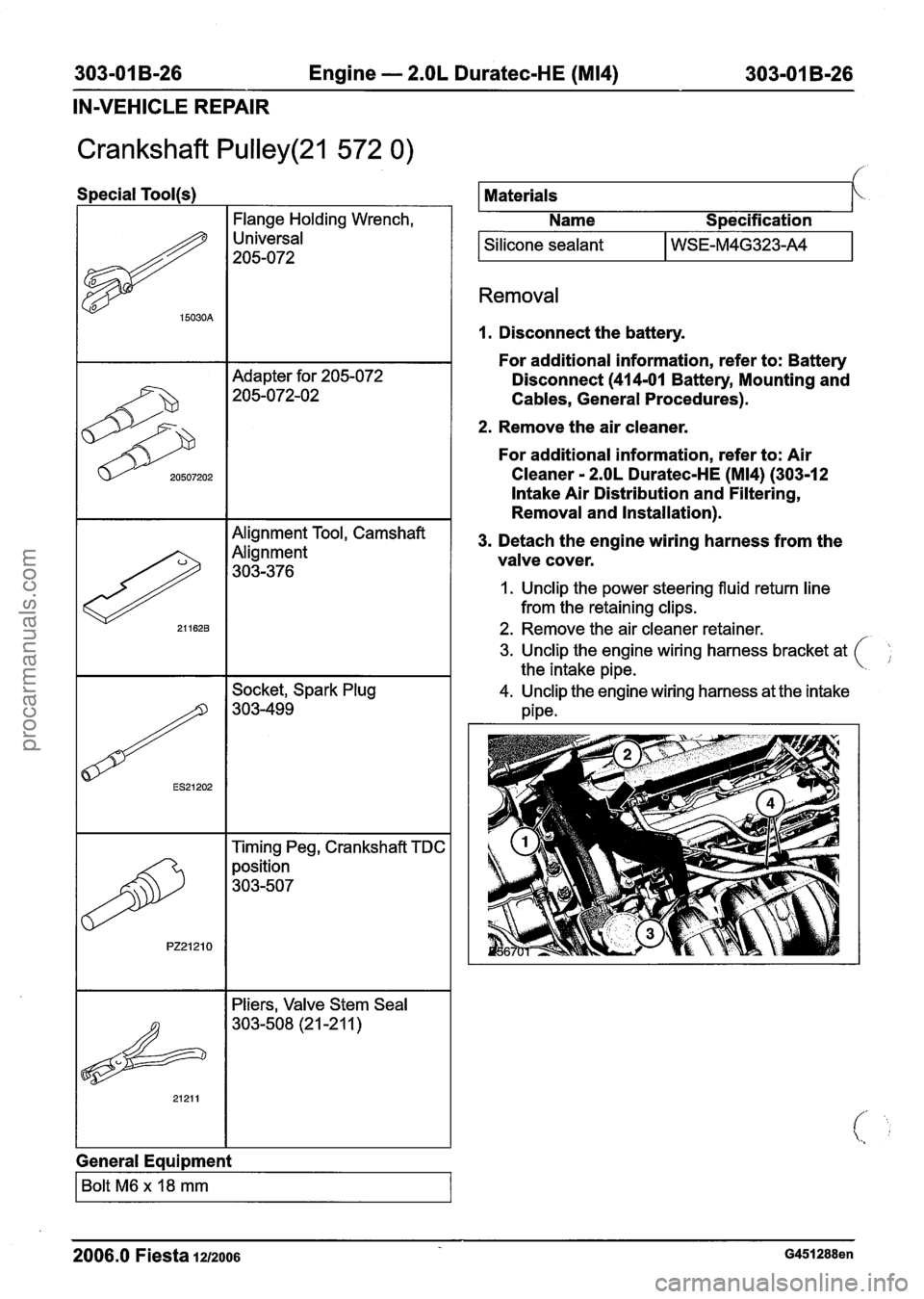
Special Tool(s)
I I Flange Holding Wrench, I
Universal
205-072
Adapter for 205-072
205-072-02
Alignment Tool, Camshaft
Alignment
303-376
Timing Peg, Crankshaft TDC
position
303-507
I I Pliers, Valve Stem Seal
General Equipment
I Bolt M6 x 18 mm I
Materials
Name
S~ecification
I Silicone sealant I WSE-M4G323-A4 I
Removal
I. Disconnect the battery.
For additional information, refer to: Battery
Disconnect (414-01 Battery, Mounting and
Cables, General Procedures).
2. Remove the air cleaner.
For additional information, refer to: Air
Cleaner
- 2.OL Duratec-HE (M14) (303-12
Intake Air Distribution and Filtering,
Removal and Installation).
3. Detach the engine wiring harness from the
valve cover.
1. Unclip the power steering fluid return line
from the retaining clips.
2. Remove the air cleaner retainer.
3. Unclip the engine wiring harness bracket at
the intake pipe.
4. Unclip the engine wiring harness at the intake
pipe.
2006.0 Fiesta 1212006 G451288en
procarmanuals.com
Page 653 of 1226
303-01 B-31 Engine - 2.OL Duratec-HE (M14) 303-01 B-31
IN-VEHICLE REPAIR
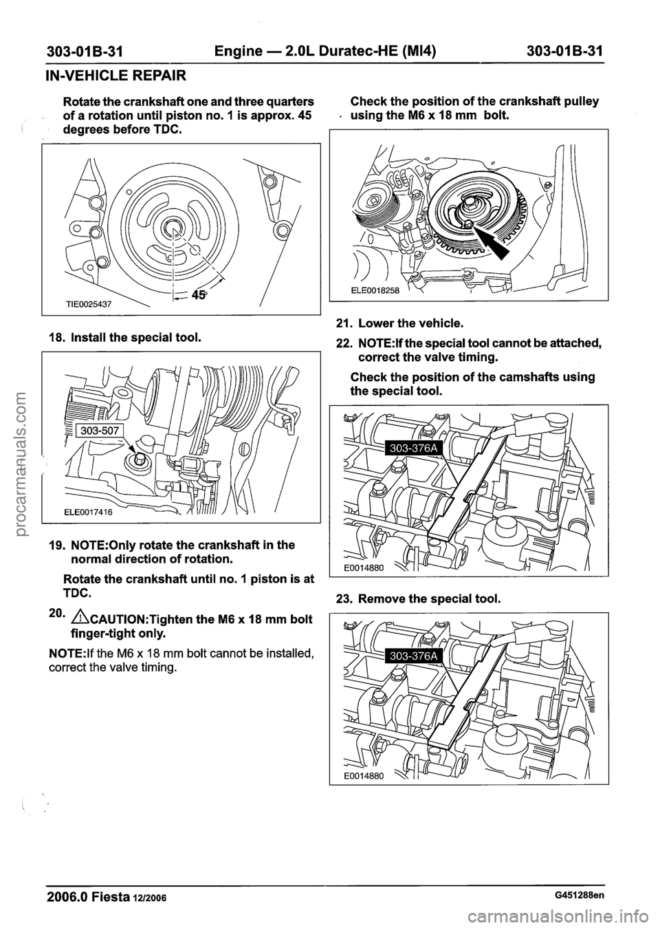
Rotate the crankshaft one and three quarters Check
the position of the crankshaft pulley
of a rotation until piston no.
1 is approx. 45 - using the M6 x 18 mm bolt.
I degrees before TDC.
18. Install the special tool.
19. N0TE:Only rotate the crankshaft in the
normal direction of rotation.
21. Lower the vehicle.
22. N0TE:H the special tool cannot be attached,
correct the valve timing.
Check the position of the camshafts using
the special tool.
Rotate the crankshaft until no.
1 piston is at
TDC.
23. Remove the special tool.
20m ~CAUTION:T~~~~~~ the M6 x 18 mrn bolt
finger-tight only.
N0TE:lf the M6 x 18 mm bolt cannot be installed,
correct the valve timing.
2006.0 Fiesta 1212006 G451288en
procarmanuals.com
Page 664 of 1226
303-01 B-42 Engine - 2.OL Duratec-HE (M14) 303-01 B-42 -
IN-VEHICLE REPAIR
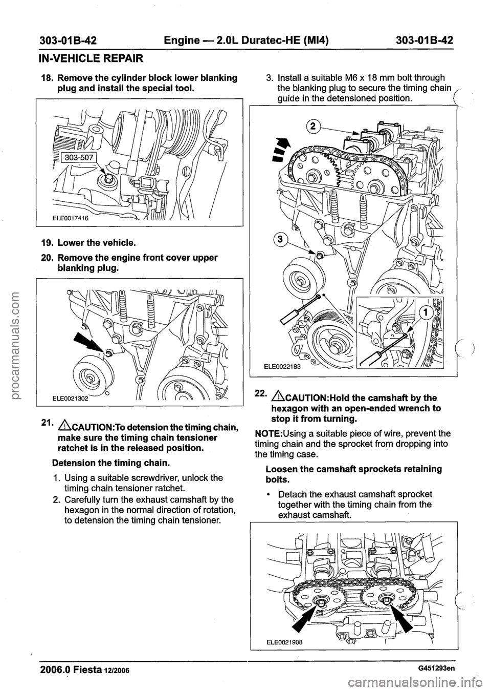
18. Remove the cylinder block lower blanking
plug and install the special tool.
19. Lower the vehicle.
20. Remove the engine front cover upper
blanking plug.
3. Install a suitable M6 x 18 mm bolt through
the blanking plug to secure the timing chain
guide in the detensioned position.
22m ACAUTION:H~I~ the camshaft by the
hexagon with an open-ended wrench to
stop it from turning.
21 ACAUTION:T~ detension the timing chain,
make sure the timing chain tensioner N0TE:Using a suitable piece of wire, prevent the
ratchet is in the released position. timing chain and the sprocket from dropping into
the timing case.
Detension the timing chain. -
Loosen the camshaft sprockets retaining
1. Using a suitable screwdriver, unlock the bolts.
timing chain tensioner ratchet.
2. Carefully turn the exhaust camshaft by the Detach the exhaust camshaft sprocket
hexagon in the normal direction of rotation, together
with the timing chain from the
exhaust camshaft.
to detension the timing chain tensioner.
2006.0 Fiesta 1212006 G451293en
procarmanuals.com
Page 665 of 1226
303-01 B-43 Engine - 2.OL Duratec-HE (M14) 303-01 B-43
IN-VEHICLE REPAIR
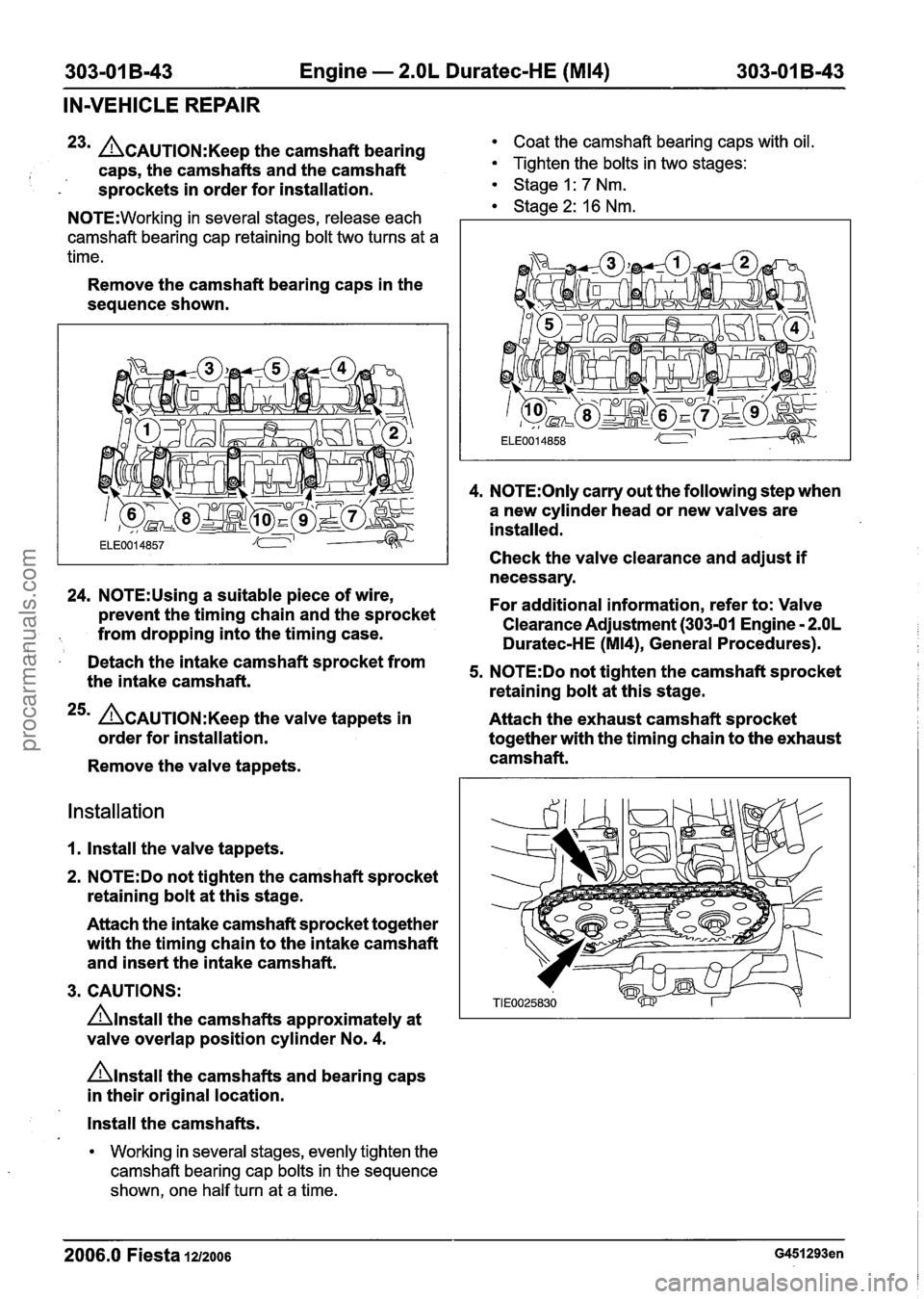
23m L?~AUTION:K~~~ the camshaft bearing Coat the camshaft bearing caps with oil.
I caps, the camshafts and the camshaft Tighten the bolts in two stages:
- s~rockets in order for installation. Stage I: 7 Nm. 1 Stage 2: 16 Nm. N0TE:Working in several stages, release each
camshaft bearing cap retaining bolt two turns at a
time.
Remove the camshaft bearing caps in the
sequence shown.
24. N0TE:Using a suitable piece of wire,
prevent the timing chain and the sprocket
from dropping into the timing case.
I Detach the intake camshaft sprocket from
the intake camshaft.
25m ACAUTION:K~~~ the valve tappets in
order for installation.
Remove the valve tappets.
Installation
1. Install the valve tappets.
2.
N0TE:Do not tighten the camshaft sprocket
retaining bolt at this stage.
Attach the intake camshaft sprocket together
with the timing chain to the intake camshaft
and insert the intake camshaft.
3. CAUTIONS:
Anstall the camshafts approximately at
valve overlap position cylinder No.
4.
nlnstall the camshafts and bearing caps
in their original location.
4. N0TE:Only carry out the following step when
a new cylinder head or new valves are
installed.
Check the valve clearance and adjust
if
necessary.
For additional information, refer to: Valve
Clearance Adjustment (303-01 Engine
- 2.OL
Duratec-HE (M14), General Procedures).
5. N0TE:Do not tighten the camshaft sprocket
retaining bolt at this stage.
Attach the exhaust camshaft sprocket
together with the timing chain to the exhaust
camshaft.
Install the camshafts.
Working in several stages, evenly tighten the
camshaft bearing cap bolts in the sequence
shown, one half turn at a time.
2006.0 Fiesta 1212006
procarmanuals.com
Page 666 of 1226
303-01 B-44 Engine - 2.OL Duratec-HE (M14) 303-01 B-44
IN-VEHICLE REPAIR
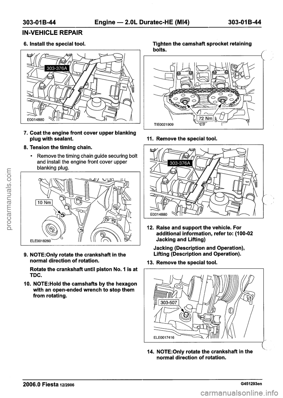
6. Install the special tool. Tighten
the camshaft sprocket retaining
bolts.
,
7. Coat the engine front cover upper blanking
plug with sealant.
11. Remove the special tool.
8. Tension the timing chain.
Remove the timing chain guide securing bolt
and install the engine front cover upper
blanking plug.
12. Raise and support the vehicle. For
additional information, refer to: (1
00-02
Jacking and Lifting) I I Jacking (Description and Operation),
9. N0TE:Only rotate the crankshaft in the Lifting
(Description and Operation).
normal direction of rotation.
13. Remove the special tool.
Rotate the crankshaft until piston No.
I is at
TDC.
10.
N0TE:Hold the camshafts by the hexagon
with an open-ended wrench to stop them
from rotating.
14.
N0TE:Only rotate the crankshaft in the <
normal direction of rotation.
2006.0 Fiesta 1212006 G451293en
procarmanuals.com
Page 667 of 1226
303-01 B-45 Engine - 2.OL Duratec-HE (M14) 303-01 B-45
IN-VEHICLE REPAIR
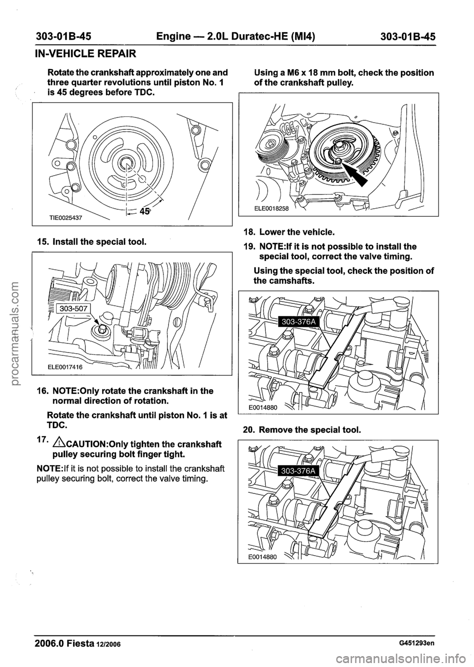
Rotate the crankshaft approximately one and
Using a M6 x 18 mm bolt, check the position
three quarter revolutions until piston No.
I of the crankshaft pulley. 1 is 45 degrees before TDC.
18. Lower the vehicle.
15. Install the special tool. 19. N0TE:lf it is not possible to install the
special tool, correct the valve timing.
Using the special tool, check the position of
the camshafts.
16. N0TE:Only rotate the crankshaft in the
normal direction of rotation.
Rotate the crankshaft until piston No.
1 is at
TDC.
20. Remove the special tool.
17' ACAUTION:O~I~ tighten the crankshaft
pulley securing bolt finger tight.
N0TE:lf it is not possible to install the crankshaft
pulley securing bolt, correct the valve timing.
2006.0 Fiesta 1212006 G451293en
procarmanuals.com