warning light FORD FIESTA 2007 Workshop Manual
[x] Cancel search | Manufacturer: FORD, Model Year: 2007, Model line: FIESTA, Model: FORD FIESTA 2007Pages: 1226, PDF Size: 61.26 MB
Page 4 of 1226
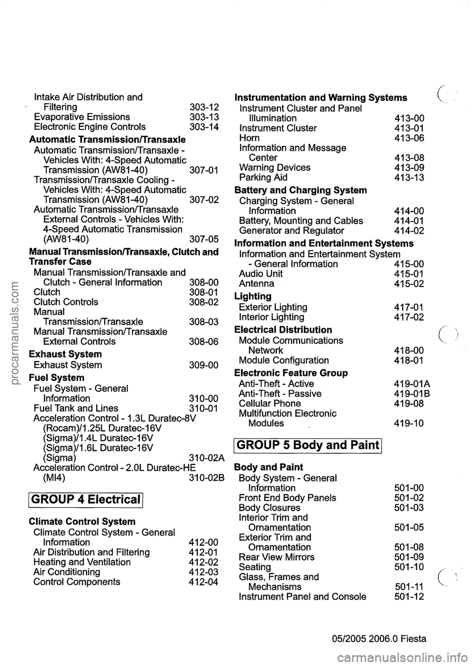
Intake Air Distribution and
- Filtering
303-1 2
Evaporative Emissions 303-1 3
Electronic Engine Controls 303-14
Automatic Transmission/Transaxle
Automatic TransmissionlTransaxle -
Vehicles With: 4-Speed Automatic
Transmission
(AW81-40) 307-01
TransmissionlTransaxle Cooling -
Vehicles With: 4-Speed Automatic
Transmission
(AW81-40) 307-02
Automatic
TransmissionlTransaxle
External Controls - Vehicles With:
4-Speed Automatic Transmission
(AW8 1 -40) 307-05
Manual Transmissionrrransaxle, Clutch and
Transfer Case
Manual TransmissionlTransaxle and
Clutch
- General Information 308-00
Clutch 308-0 1
Clutch Controls 308-02
Manual
Transmission/Transaxle 308-03
Manual TransmissionlTransaxle
External Controls 308-06
Exhaust System
Exhaust System 309-00
Fuel System
Fuel System - General
Information 31 0-00
Fuel Tank and Lines
31 0-01
Acceleration Control - I .3L Duratec-8V
(Rocam)ll.25L Duratec-I 6V
Instrumentation and Warning Systems
lnstrument Cluster and Panel
(
Illumination 41 3-00
Instrument Cluster
413-01
Horn 41 3-06
lnformation and Message
Center 41 3-08
Warning Devices
4 1 3-09
Parking Aid 41 3-1 3
Battery and Charging System
Charging System - General
Information 4 14-00
Battery, Mounting and Cables 414-01
Generator and Regulator 41 4-02
lnformation and Entertainment Systems
lnformation and Entertainment System
- General Information 41 5-00
Audio Unit 41 5-01
Antenna 41 5-02
Lighting
Exterior Lighting 41 7-01
Interior Lighting 4 1 7-02
Electrical Distribution
Module Communications ( 'j
Network 41 8-00
Module Configuration 41 8-01
Electronic Feature Group
Anti-Theft - Active 419-01A
Anti-Theft
- Passive 41 9-01 B
Cellular Phone 41 9-08
Multifunction Electronic
Modules 41 9-1 0
Climate Control System
Climate Control System - General
Information
Air Distribution and Filtering
Heating and Ventilation
Air Conditioning
Control Components
(Sigma)ll.4L Duratec-I 6V
lnterior Trim and
Ornamentation
Exterior Trim and
Ornamentation
Rear View Mirrors
Seating
Glass, Frames and
Mechanisms
(Sigma)/l .6L Duratec-1 6V
Instrument Panel and Console 501 -1 2
0512005 2006.0 Fiesta
GROUP 5 Body and Paint
(Sigma) 3 1 0-02A
Acceleration Control
- 2.OL Duratec-HE Body and Paint
(M14) 31 0-028 Body System - General
Information 501 -00
GROUP 4 Electrical Front End Body Panels 50 1 -02
Body Closures 50 1 -03
procarmanuals.com
Page 13 of 1226
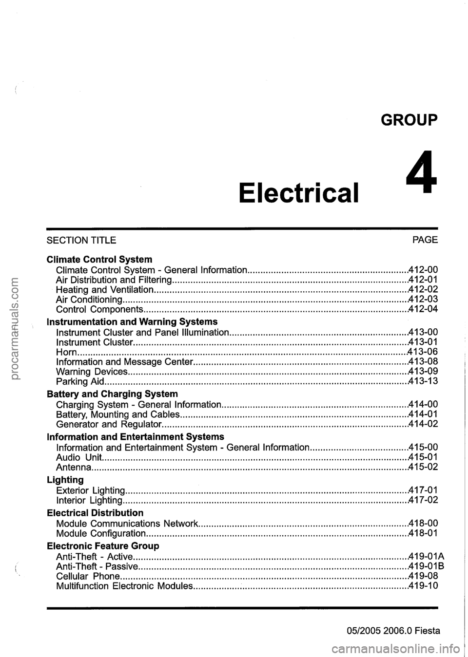
GROUP
Electrical
SECTION TITLE PAGE
Climate Control System
.......................................................... Climate Control System . General Information 42-00
........................................................................\
................... Air Distribution and Filtering 412-01
........................................................................\
......................... Heating and Ventilation .41 2-02
........................................................................\
..................................... Air Conditioning .41 2.03
........................................................................\
............................. Control Components .41 2.04
i
Instrumentation and Warning Systems
.................................................................... Instrument Cluster and Panel Illumination -41 3-00
........................................................................\
................................. Instrument Cluster .41 3-01
........................................................................\
...................................................... Horn -41 3-06
Information and Message Center ........................................................................\
........... 41 3-08
........................................................................\
................................... Warning Devices -41 3-09
........................................................................\
............................................. Parking Aid 413-1 3
Battery and Charging System
Charging System . General Information ..................................................................... 14-00
........................................................................\
............... Battery, Mounting and Cables -41 4-01
........................................................................\
...................... Generator and Regulator .41 4-02
lnformation and Entertainment Systems
Information and Entertainment System . General Information ..................................... .41 5-00
Audio Unit ........................................................................\
.............................................. 15-01
........................................................................\
................................................. Antenna .41 5-02
Lighting
........................................................................\
.................................... Exterior Lighting .41 7.01
........................................................................\
..................................... Interior Lighting -41 7-02
Electrical Distribution
........................................................................\
......... Module Communications Network 18-00
........................................................................\
............................. Module Configuration 41 8-01
Electronic Feature Group
Anti-Theft - Active ........................................................................\
.................................. 419-OIA
........................................................................\
............................... Anti-Theft . Passive .4 I 9-0 I B
........................................................................\
.............................. Cellular Phone .........4 19-08
........................................................................\
........... Multifunction Electronic Modules 41 9-1 0
0512005 2006.0
Fiesta
procarmanuals.com
Page 24 of 1226
100=00=8 General Information 100=00=8
DESCRIPTION AND OPERATION
drowsiness. In extreme cases, loss of
consciousness may result. Long term exposure to
vapor concentrations may result in adverse health
effects.
Prolonged contact with the skin may have a
defatting effect which may lead to skin irritation
and in some cases, dermatitis.
Splashes entering the eye will cause discomfort
and possible damage.
Any spraying should preferably be carried out in
exhaust ventilated booths, removing vapors and
spray droplets from the breathing zone.
Wear appropriate gloves, eye and respiratory
protection. Asbestos dust
waste should be dampened, placed
in a sealed container and marked for safe disposal.
If any cutting or drilling is attempted on materials
(
containing asbestos the item should be dampened "
and only hand tools or low speed power tools used.
Battery Acids
See also Acids and Alkalis.
Gases released during charging are explosive.
Never use naked flames or allow sparks near
charging or recently charged batteries.
Make sure there is adequate ventilation.
Brake and Clutch Linings and Pads
Antifreeze
See Asbestos.
See also Fire, Solvents.
For example isopropanol, ethylene glycol,
methanol.
Highly flammable, flammable, combustible.
Used in vehicle coolant systems, brake air pressure
systems, screenwash solutions.
Vapors may be given off from coolant antifreeze
(glycol) when heated. Avoid breathing these
vapors.
Antifreeze may be absorbed through the skin in
toxic or harmful quantities. Antifreeze, if swallowed,
can be fatal and MEDICAL ATTENTION SHOULD
BE SOUGHT IMMEDIATELY.
These products must not be used in any cooling
or industrial water system that is connected or
linked to general, food preparation or drinking water
supplies.
Asbestos
See also Warning Symbols on Vehicles at the end
of this subsection.
Breathing asbestos dust may cause lung damage
or, in some cases, cancer.
Used in brake and clutch linings, transmission
brake bands and gaskets.
The use of drum cleaning units, vacuum cleaning
or damp wiping is preferred.
Brake Fluids (Polyal kylene Glycols)
See also Fire.
Splashes to the skin and eyes are slightly irritating.
Avoid skin and
eye'contact as far as possible.
Inhalation vapor hazards do not arise at ambient
temperatures because of the very low vapor
pressure.
Brazing
See Welding.
Chemical Materials
See also Legal Aspects.
Chemical materials such as solvents, sealers,
adhesives, paints, resin foams, battery acids,
antifreeze, brake fluids, fuels, oils and grease
should always be used with caution and stored and
handled with care. They may be toxic, harmful,
corrosive, irritant or highly flammable and give rise
to hazardous fumes and dusts.
The effects of excessive exposure to chemicals may be immediate or delayed; briefly experienced
or permanent; cumulative; superficial; life
threatening; or may reduce life expectancy.
2006.0 Fiesta 1212006 GI 7372en
procarmanuals.com
Page 33 of 1226
100-00-1 7 General Information 100-00-1 7
DESCRIPTION AND OPERATION
The flame is bright, and eye protection should be - used, but the ultra-violet emission is much less
than that from arc welding, and lighter filters may
be used.
The process itself produces few toxic fumes, but
such fumes and gases may be produced from
coatings on the work, particularly during cutting
away of damaged body parts, and inhalation of the
fumes should be avoided.
In brazing, toxic fumes may be produced from the
metals in the brazing rod, and a severe hazard
may arise if brazing rods containing cadmium are
used. In this event particular care must be taken
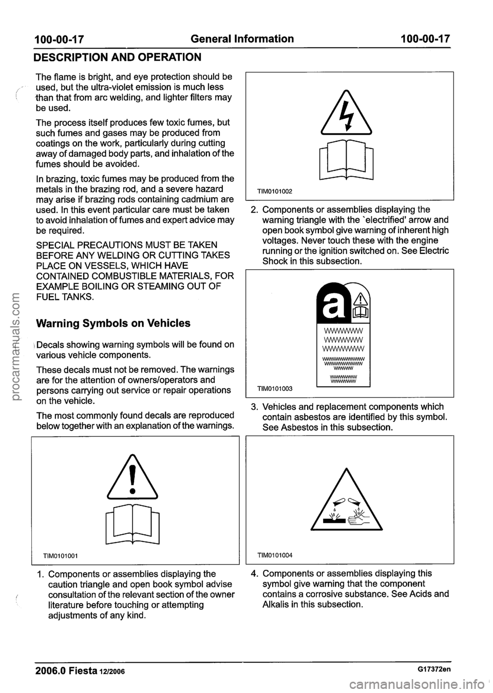
2. Components or assemblies displaying the
to avoid inhalation of fumes and expert advice may
warning triangle with the 'electrified' arrow and
be required. open book symbol
give warning of inherent high
SPECIAL PRECAUTIONS MUST BE TAKEN voltages.
Never touch these with the engine
BEFORE ANY WELDING OR CUTTING TAKES running
or the ignition switched on. See Electric
PLACE ON VESSELS, WHICH HAVE Shock
in this subsection.
CONTAINED COMBUSTIBLE MATERIALS, FOR
EXAMPLE BOILING OR STEAMING OUT OF
FUEL TANKS.
Warning Symbols on Vehicles
( i Decals showing warning symbols will be found on
various vehicle components.
These decals must not be removed. The warnings
are for the attention of
owners/operators and
persons carrying out service or repair operations
on the vehicle.
3. Vehicles and replacement components which
The most commonly found decals are reproduced
contain asbestos are identified by this symbol.
below together with an explanation of the warnings.
See Asbestos in this subsection.
1. Components or assemblies displaying the
caution triangle and open book symbol advise
consultation of the relevant section of the owner
literature before touching or attempting
adjustments of any kind. 4. Components or assemblies displaying this
symbol give warning that the component
contains a corrosive substance. See Acids and
Alkalis in this subsection.
2006.0 Fiesta 1212006 GI 7372en
procarmanuals.com
Page 35 of 1226
100-00-1 9 General Information 100-00-1 9
DESCRIPTION AND OPERATION
Standard Workshop Practices
Vehicle in Workshop
When working on a vehicle in the workshop always
make sure that:
- the parking brake is applied or the wheels are
securely chocked to prevent the vehicle moving
forwards or backwards.
- the key is removed from key operated hood
locks before any work is carried out around the
front of the vehicle.
- if the engine is to be run, there is adequate
ventilation, or an extraction hose to remove
exhaust fumes.
- there is adequate room to raise the vehicle and
remove the wheels, if necessary.
- fender covers are always fitted if any work is to
be carried out in the engine compartment.
- the battery is disconnected if working on the
engine, underneath the vehicle, or if the vehicle
is raised.
Alternative Fuel - Dons
- Do work on the vehicle in a designated area,
that is well ventilated and with access restricted
to qualified personnel only.
- Install new warning labels to their original
locations.
- If possible always isolate the alternative fuel
tank, and run the vehicle on the alternative fuel
until it automatically switches to its normal fuel
prior to taking the vehicle into the workshop
service area.
- Only use tested and approved components and
pipes when repairing or servicing
LPG and CNG
systems.
Alternative Fuel - Do Nots
- Do not vent off LPG fuel.
- Do not use shop air pressure to force LPG fuel
from the fuel tank.
( A CAUTION:When electric arc welding on a - Do not use paint drying ovens above 40°C for vehicle, always disconnect the generator any alternative fuel vehicle. LPG and CNG fuel wiring to prevent the possibility of a surge tanks must be removed from the vehicle prior of current causing damage to the internal to being put into paint drying ovens above 40°C. components of the generator. - Do not modify the system or install new - if using welding equipment on the vehicle, a
components that are not designed for gas
suitable fire extinguisher is readily available.
vehicles.
Alternative Fuel
A WARNING:When servicing the fuel system
always follow the recommended
procedures. Failure to follow these
instructions may result in personal injury.
If the odor of liquefied petroleum gas (LPG) or
compressed natural gas
(CNG) is present in the
air in the workshop, warn all persons in the area
to:
- extinguish all flames and lighted tobacco.
- shut off electrical and air powered equipment.
- evacuate the area.
- ventilate the area.
- contact the fire control authorities.
- remove the vehicle to a dedicated, ventilated
area.
- Do not evacuate fuel tanks unless there is repair
that requires the removal of the fuel tank.
- Do not work on the fuel lines or system
components unless the alternative fuel has been
evacuated and the pressure in the system
reduced to atmospheric or less.
- Do not use anything other than the specified
leak detector fluid to trace fuel leaks.
Be aware of situations that may cause the
LPG or I
CNG fuel system to vent off fuel, such as: I
- extremely hot days.
- parking by a space heater.
- hoisting a vehicle up near a ceiling heater.
Only fully trained personnel, who are conversant
with local standards, are to work on alternative fuel
vehicles.
2006.0 Fiesta 1212006 GI 7373en
procarmanuals.com
Page 39 of 1226
100-00-23 General Information 100-00-23
DESCRIPTION AND OPERATION
RoadIRoller Testing
I Road or roller testing may be carried out for various
reasons and a procedure detailing pre-test checks,
engine starting and stopping, pre-driving checks,
on-test checks and final checks to be completed
on completion of the test is given below.
Unless complete vehicle performance is being
checked, the full road test procedure need not be
carried out. Instead, those items particularly
relevant to the
system(s) being checked can be
extracted.
Pre-Test Checks
A WARNING:lf the brake system hydraulic
fluid level is low, pedal travel is excessive
or a hydraulic leak is found, do not attempt
to road test the vehicle until the reason for
the low fluid level, excessive pedal travel
or hydraulic leak is found and rectified.
It is suggested that pre-test checks and functional
tests of those systems and circuits which affect the
safe and legal operations of the vehicle, such as
( , brakes, lights and steering, should always be
carried out before the road or roller test.
With the ignition switched off, check:
- the engine oil level.
- the engine coolant level.
- the tires, for correct pressure, compatible types
and tread patterns, and wear within limits.
- that there is sufficient fuel in the tank to
complete the test.
- all around the engine, transmission and under
the vehicle for oil, coolant, hydraulic and fuel
leaks. Make a note of any apparent leaks and
wipe off the surrounding areas to make it easier
to identify the extent of the leak on completion
of the test.
Starting the Engine
N0TE:On initial drive away from cold and within
the first 1.5 km (1 mile), do not depress the
accelerator pedal beyond half travel until the
vehicle has attained a minimum speed of
25 kmlh
(15 mileslh). Never operate at high engine speed
or with the accelerator pedal at full travel whilst the
engine is cold.
With the ignition switched off, check:
- that the parking brake is applied.
- that the gear lever is in the neutral position.
- that all instrument gauges (except fuel gauge)
read zero.
With the ignition switched on, check:
- that the ignition controlled warning lamps are
illuminated.
- that the engine temperature gauge registers a reading compatible with the engine temperature.
- that the fuel gauge registers a reading
appropriate to the fuel level in the tank.
- the operation of the parking brake warning lamp
and fluid level warning indicator.
Road or Roller Testing
A CAUTI0N:lf road testing, check the brake
operation while still traveling at low speed
before continuing with the test. If the
brakes pull to one side, or appear to be
otherwise faulty, do not continue with the
road test until the fault has been found and
rectified.
During the road or roller test, check:
- that the clutch pedal operation is not stiff or
heavy.
- that the initial gear engagement is smooth and
there is no evidence of clutch drag.
- that the parking brake control operates smoothly
and releases quickly and completely.
- that the clutch takes up the drive smoothly,
without slip or judder.
- that gear changing is smooth with no abnormal
noises or vibrations from the transmission.
- the engine power output is satisfactory, full
power is achieved, acceleration is smooth and
pedal operation is not stiff or heavy, and engine
speed returns to idle correctly.
- there is no excessive or abnormally colored
smoke from the engine under normal driving,
heavy load or overrun conditions.
- that steering operation, including power steering
(if equipped), is smooth, accurate, not
excessively heavy or with excessive free play
or vibration.
- that the steering does not pull to one side and
self centers smoothly after cornering.
2006.0 Fiesta 1212006 GI 7375en
procarmanuals.com
Page 40 of 1226
100-00-24 General Information 100-00-24
DESCRIPTION AND OPERATION
- that the speedometer, coolant temperature - oil, coolant, hydraulic, air and fuel leaks.
gauge and tachometer (if equipped) register the - abnormal temperature of any moving
correct readings and operate correctly.
components or assemblies, for example wheel
(
- that the switches and controls operate smoothly hubs, transmission and axle, which might
and positively, warning and indicator lamps
indicate over tightness or lack of lubrication.
operate correctly and the direction indicator
control self cancels when the steering is
returned to the straight ahead position.
- that the heating and ventilation systems operate
correctly and effectively.
- the brake operation and efficiency.
Brake Testing
A WARNING:When brake testing, avoid
breathing the fumes from hot brakes, this
may contain asbestos dust which is
hazardous to health. Failure to follow this
instruction may result in personal injury.
For additional information, refer to: Health
and Safety Precautions
(1 00-00 General
Information, Description and Operation).
CAUTIONS:
A Avoid brake testing on busy roads where
it may cause inconvenience or danger to
other road users.
A Brake testing which includes heavy brake
applications should not be carried out with
new brake
padsldiscs or liningsldrums
until the components have bedded-in. New
brake friction components will not reach
full efficiency until the bedding-in process
is complete.
Test the brakes at several speeds within the normal
operating range using both light and heavy pedal
pressure. Note any tendency to snatch, pull or
drag, and any undue delay in application or
release.
Allow the vehicle to coast and note any tendency
to pull to one side, or evidence that the brakes are
binding.
After stopping the vehicle (not immediately after a
period of heavy braking), carefully check the brake
temperature.
A brake disc or brake drum that feels
hot or is appreciably hotter than the others,
indicates that the brake is binding.
After completion of the test, check for:
2006.0 Fiesta 1212006 GI 7375en
procarmanuals.com
Page 175 of 1226
206-00-3 Brake System - General Information 206-00-3
DIAGNOSIS AND TESTING
Brake System
The brakes system operates by transferring effort
applied to the brake pedal by the driver to the
brakes at each wheel.
The braking effort is distributed to each wheel,
using a hydraulic system. The system is assisted
using a vacuum brake booster that reduces pedal
effort and increases hydraulic pressure.
The parking brake operates on the rear wheels
and is applied using a hand operated control.
lnspection and Verification
N0TE:Before carrying out any diagnosis, make
sure that the brake system warning indicator is
functional.
1. Verify the customer concern.
2. Visually inspect for obvious signs of mechanical
damage.
3. If an obvious cause for an observed or reported
concern is found, correct the case (if possible)
before proceeding to the next step.
4. If the cause if not visually evident, verify the
symptom and refer to the Symptom Chart.
Visual lnspection Chart
Road Test
1.
Perform a road test to compare actual vehicle
braking performance with the performance
standards expected by the driver. The ability of the
test driver to make valid comparisons and detect
performance deficiencies will depend on
experience.
Mechanical
- Tire pressure
- Wheels and tires
- Fluid leak from brake line(s)
The driver should have a thorough knowledge of
the brake system operation and accepted general
performance guidelines to make good comparisons
, and detect performance concerns.
An experienced technician will always establish a
route that will be used for all brake diagnosis road
tests. The road selected will be reasonably smooth and level. Gravel
or bumpy roads are not suitable
because the surface does not allow the tires to grip
the road equally. Crowned roads should be avoided
because of the large amount of weight shifted to
the low set of wheels on this type of road. Once
the route is established and consistently used, the
road surface variable can be eliminated from the
test results.
Before a road test, get a complete description of
the customer concerns or suspected condition.
From the description, the technician will be able to
match possible causes with symptoms. Certain
components will be identified as possible sources
while others will be eliminated by the evidence.
More importantly, the customer description can
reveal unsafe conditions which should be checked
or corrected before a road test. The description will
also help form the basic approach to the road test
by narrowing the concern to specific components,
vehicle speed or conditions.
Begin the road test with a general brake
performance check. Using the description of the
concern, test the brakes at different vehicle speeds
using both light and heavy pedal pressure.
Determine if the concern is in the front or rear
braking system. First use the foot brake and then
the parking brake. If the condition
(i.e. pull,
vibration, pulsation) occurs only on operation of
the parking brake, the concern is in the rear brake
system.
If the condition occurs when the foot brake
is depressed, the concern is in the front brake
system.
Avoid locking the brakes and sliding the tires. This
condition will not indicate brake efficiency. A heavily
braked but turning wheel will stop the vehicle in a
shorter distance than locked wheels.
If the concern becomes evident during this check,
make sure it fits the description given before the
road test. If the concern is not evident, attempt to
duplicate the condition using the information from
the description.
If a concern exists, use the Brake System Symptom
Chart in order to isolate it to a specific sub-system
and condition description. From this description, a
list of possible sources can be used to further
narrow the cause to a specific component or
condition.
- -
2006.0 Fiesta 1212006 G28494en
procarmanuals.com
Page 202 of 1226
Brake System - General Information
DIAGNOSIS AND TESTING
evidence of a brake concern. Check for the brake
warning indicator illumination and the fluid level in
the master cylinder reservoir.
Normal Conditions
The following conditions are considered normal
and are not indications that the brake master
cylinder is in need of service.
- Modern brake systems are not designed to
produce as hard a pedal effort as in the past.
Complaints of light pedal efforts should be
compared to pedal efforts of another vehicle, of
the same model and year.
- During normal operation of the brake the fluid
level in the reservoir will rise during brake
application and fall during release. The net fluid
level
(i.e., after brake application and release)
will remain unchanged.
- A trace of brake fluid will exists on the brake
booster shell below the master cylinder
mounting flange. This results from the normal
lubricating action of the master cylinder bore
end seal.
- The fluid level will fall with brake shoe and lining
wear.
Abnormal Conditions
N0TE:Prior to performing any diagnosis, make
sure the brake system warning indicator is
functional.
Changes in brake pedal feel or travel are indicators
that something could be wrong with the braking system. The diagnostic procedure and techniques
use brake pedal feel, warning indicator illumination
and low brake fluid level as indicators in diagnosing
braking system concerns. The following conditions
are considered abnormal and indicate that the
brake master cylinder is in need of service.
- The brake pedal effort is excessive. This may
be caused by a bind or obstruction in the pedal
.
or linkage, clogged fluid control valve or ( ' insufficient booster vacuum.
- The rear brakes lock up during light pedal force.
This may be caused by incorrect tire pressures,
grease or fluid on the brake shoes and linings,
damaged brake shoes and linings, incorrectly
adjusted parking brake, or damaged or
contaminated brake pressure control valves.
- The brake pedal effort is erratic. This condition
could be caused by a brake booster malfunction,
extreme caliper piston knock back or incorrectly
installed brake shoes and linings.
- The brake warning indicator is ON. This may
be caused by low fluid level, ignition wire routing
too close to the fluid level indicator assembly,
or float assembly damage.
Bypass Condition Test
1. Check the fluid in brake master cylinder. Fill the
brake master cylinder reservoir if low or empty.
2. Observe the fluid level in the brake master
cylinder reservoir. If after several brake
applications, the fluid level remains the same,
measure the wheel turning torque required to
rotate the wheels with the brakes applied as
follows:
Place the transaxle in NEUTRAL and raise and
support the vehicle. REFER to: (1 00-02 Jacking
and Lifting)
Jacking (Description and Operation),
Lifting (Description and Operation).
Apply the brakes with a minimum of 445 N (100
Ib) and hold for approximately 15 seconds. With
the brakes still applied, exert a torque on the front
wheels of 10.1 Nm (75
1b.R). If either wheel rotates,
install a new brake master cylinder. REFER to:
(206-06 Hydraulic Brake Actuation)
- The brake pedal goes down fast. This could be Brake Master Cylinder - RHD (Removal and
caused by an external or internal leak. Installation),
- The brake
pedal eases down slowly. This could Brake Master Cylinder - LHD
(Removal and
be caused by an external or internal leak. Installation).
- The
brake pedal is low and or feels spongy. This
condition may be caused by no fluid in the brake
Non-Pressure Leaks master cylinder reservoir, reservoir cap vent
holes clogged or air in the hydraulic system.
Any empty brake master cylinder reservoir
condition may be caused by two types of
non-pressure external leaks.
2006.0 Fiesta 1212006
procarmanuals.com
Page 439 of 1226
303-00-1 7 Engine System - General Information 303-00-1 7
DIAGNOSIS AND TESTING
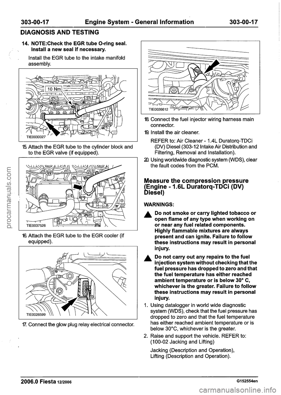
14. N0TE:Check the EGR tube O-ring seal.
Install a new seal
if necessary. I
, Install the EGR tube to the intake manifold
assembly.
18 Connect the fuel injector wiring harness main
connector.
19 Install the air cleaner.
REFER to: Air Cleaner
- 1.4L Duratorq-TDCi
15 Attach the EGR tube to the cylinder block and (DV) Diesel (303-12 Intake Air Distribution
and
to the EGR valve (if equipped). Filtering, Removal
and Installation).
Using worldwide diagnostic system (WDS), clear
the fault codes from the PCM.
Measure the compression pressure
Engine
- 1.6L Duratorq-TDCi (DV)
biesel)
WARNINGS:
A Do not smoke or carry lighted tobacco or
open flame of any type when working on
or near any fuel related components.
Highly flammable mixtures are always
16 Attach the EGR tube to the EGR cooler (if present and can ignite. Failure to follow
equipped). these instructions may result in personal
injury.
Do not carry out any repairs to the fuel
injection system without checking that the
fuel pressure has dropped to zero and that
the fuel temperature has either reached
ambient temperature or is below
30' C,
whichever is the greater. Failure to follow
these instructions may result in personal
injury.
I. Using datalogger in world wide diagnostic
system (WDS), check that the fuel pressure has
dropped to zero and that the fuel temperature
17. Connect the glow plug relay electrical connector. has
either reached ambient temperature or is
below 30°C, whichever is the greater.
2. Raise and support the vehicle. REFER to:
(1 00-02 Jacking and Lifting)
Jacking (Description and Operation),
Lifting (Description and Operation).
2006.0 Fiesta 1212006 GI 52554en
procarmanuals.com