Oil pump FORD FIESTA 2007 Workshop Manual
[x] Cancel search | Manufacturer: FORD, Model Year: 2007, Model line: FIESTA, Model: FORD FIESTA 2007Pages: 1226, PDF Size: 61.26 MB
Page 325 of 1226
211 -00-5 Steering System - General Information 211 -00-5
DIAGNOSIS AND TESTING
Steering System
/ Special Tool(s)
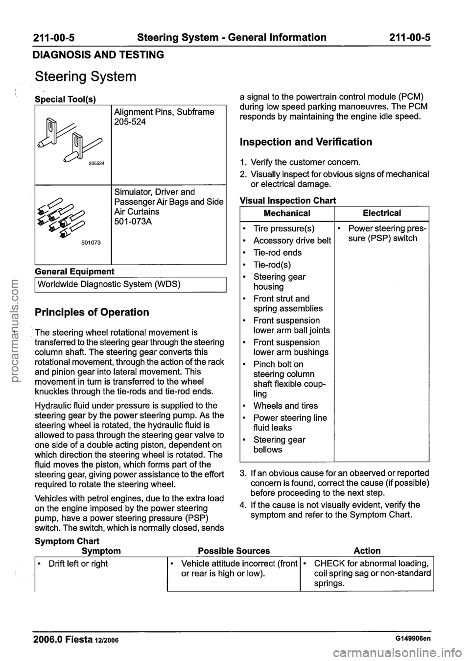
Alignment Pins, Subframe
205-524
Simulator, Driver and
passenger ~ir Bags and Side
Air Curtains 50
1 -073A
General Eaui~ment
I Worldwide Diagnostic System (WDS) I
Principles of Operation
The steering wheel rotational movement is
transferred to the steering gear through the steering
column shaft. The steering gear converts this
rotational movement, through the action of the rack
and pinion gear into lateral movement. This
movement in turn is transferred to the wheel
knuckles through the tie-rods and tie-rod ends.
Hydraulic fluid under pressure is supplied to the
steering gear by the power steering pump. As the
steering wheel is rotated, the hydraulic fluid is
allowed to pass through the steering gear valve to
one side of a double acting piston, dependent on
which direction the steering wheel is rotated. The
fluid moves the piston, which forms part of the
steering gear, giving power assistance to the effort
required to rotate the steering wheel.
Vehicles with petrol engines, due to the extra load
on the engine imposed by the power steering
pump, have a power steering pressure (PSP)
switch. The switch, which is normally closed, sends a signal
to the powertrain control module (PCM)
during low speed parking manoeuvres. The PCM
responds by maintaining the engine idle speed.
lnspection and Verification
1. Verify the customer concern.
2. Visually inspect for obvious signs of mechanical
or electrical damage.
Visual lnspection Chart
I Mechanical I Electrical I
Tire pressure(s)
Accessory drive belt
Tie-rod ends
Tie-rod (s)
Steering gear housing
Front strut and
spring assemblies
Front suspension
lower arm ball joints
Front suspension
lower arm bushings
Pinch bolt on
steering column
shaft flexible coup-
ling Power
steering pres-
sure (PSP) switch
Wheels and tires
Power steering line
fluid leaks
Steering gear
bellows
3. If an obvious cause for an observed or reported
concern is found, correct the cause (if possible)
before proceeding to the next step.
4. If the cause is not visually evident, verify the
symptom and refer to the Symptom Chart.
Symptom Chart
Symptom Possible Sources Action
Drift left or right
2006.0 Fiesta 1212006 Gl49906en
Vehicle attitude incorrect (front
or rear is high or low). CHECK for abnormal loading,
coil spring sag or non-standard
springs.
procarmanuals.com
Page 436 of 1226
303-00-1 4 Engine System - General Information 303-00-1 4
DIAGNOSIS AND TESTING
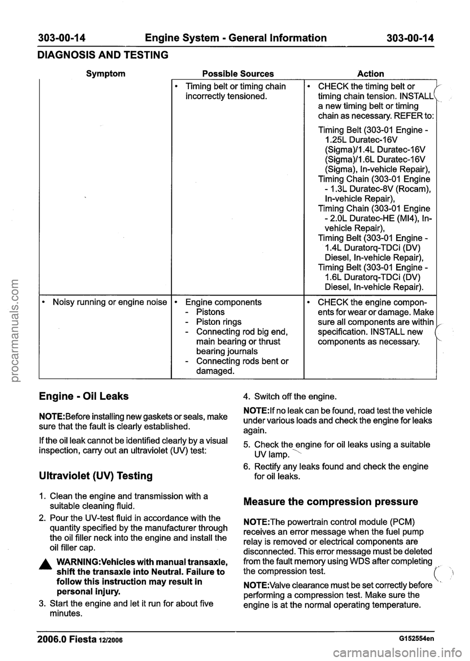
Symptom
Possible Sources
Action
Timing belt or timing chain
incorrectly tensioned.
CHECK the timing belt or
timing chain tension. INSTALL
a new timing belt or timing
chain as necessary. REFER to:
Timing Belt (303-01 Engine
-
I .25L Duratec-1 6V
(Sigma)/l.4L Duratec-1 6V
(Sigma)/l .6L Duratec-1 6V
(Sigma), In-vehicle Repair),
Timing Chain (303-01 Engine
- 1.3L Duratec-8V (Rocam),
In-vehicle Repair),
Timing Chain (303-01 Engine
- 2.OL Duratec-HE (M14), In-
vehicle Repair),
Timing Belt
(303-01 Engine -
1.4L Duratorq-TDCi (DV)
Diesel, In-vehicle Repair),
Timing Belt (303-01 Engine
-
I .6L Duratorq-TDCi (DV)
Diesel, In-vehicle Repair).
Noisy running or engine noise
Engine components
- Pistons
- Piston rings
- Connecting rod big end,
main bearing or thrust
bearing journals
- Connecting rods bent or
damaged.
CHECK the engine compon-
ents for wear or damage. Make
sure all components are within
specification. INSTALL new
components as necessary.
Engine - Oil Leaks
NOTE: Before installing new gaskets or seals, make
sure that the fault is clearly established.
If the oil leak cannot be identified clearly by a visual
inspection, carry out an ultraviolet
(UV) test:
Ultraviolet (UV) Testing
1. Clean the engine and transmission with a
suitable cleaning fluid.
2. Pour the UV-test fluid in accordance with the
quantity specified by the manufacturer through
the oil filler neck into the engine and install the
oil filler cap.
A WARN1NG:Vehicles with manual transaxle,
shift the transaxle into Neutral. Failure to
follow this instruction may result in
personal injury.
3. Start the engine and let it run for about five
minutes. 4.
Switch off the engine.
N0TE:lf no leak can be found, road test the vehicle
under various loads and check the engine for leaks
again.
5. Check the engine for oil leaks using a suitable
UV lamp.
'
6. Rectify any leaks found and check the engine
for oil leaks.
Measure the compression pressure
N0TE:The powertrain control module (PCM)
receives an error message when the fuel pump
relay is removed or electrical components are
disconnected. This error message must be deleted
from the fault memory using WDS after completing
the compression test.
(' ,
'I N0TE:Valve clearance must be set correctly before
performing a compression test. Make sure the
engine is at the normal operating temperature.
2006.0 Fiesta 1212006 GI 52554en
procarmanuals.com
Page 442 of 1226
303-00-20 Engine System - General Information 303-00-20
DIAGNOSIS AND TESTING
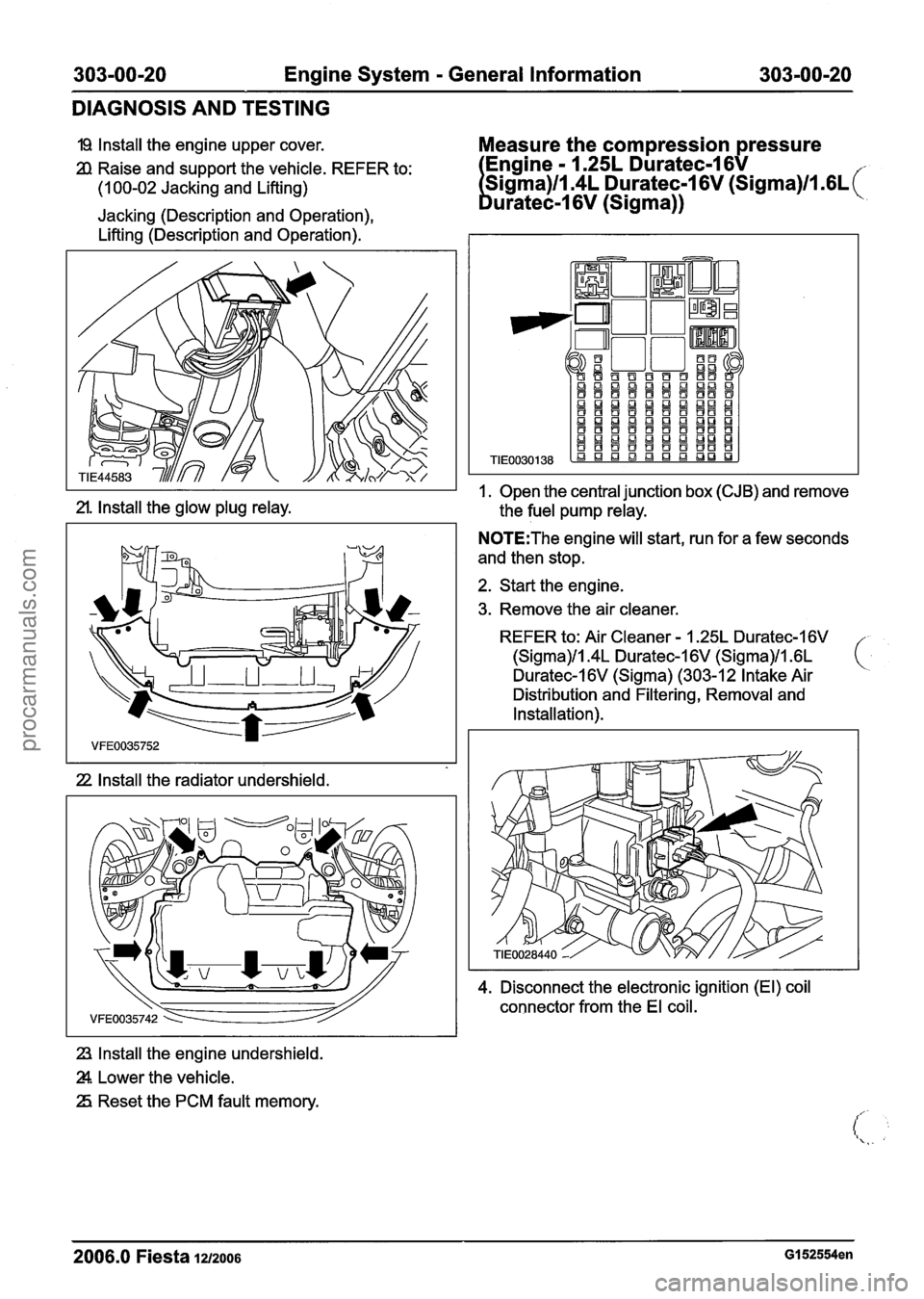
I9 Install the engine upper cover. Measure the compression pressure
2l Raise and support the vehicle. REFER to: - 1.25L Duratec-1 6V
(1 00-02 Jacking and Lifting) 6V (sigrna)/l .GL (
Jacking (Description and Operation),
Lifting (Description and Operation).
2l. Install the glow plug relay.
22 Install the radiator undershield.
23, Install the engine undershield.
Z. Lower the vehicle.
25 Reset the PCM fault memory.
I. Open the central junction box (CJB) and remove
the
fuel pump relay.
N0TE:The engine will start, run for a few seconds
and then stop.
2. Start the engine.
3. Remove the air
cleaner.
REFER to: Air Cleaner - 1.25L Duratec-1 6V
(Sigma)/l.4L Duratec-1 6V (Sigma)ll .6L ( Duratec-I 6V (Sigma) (303-1 2 Intake Air
Distribution and
Filtering, Removal and
Installation).
4. Disconnect the electronic ignition (El) coil
connector from the El coil.
- -- - - -
2006.0 Fiesta 1212006 GI 52554en
procarmanuals.com
Page 444 of 1226
303-00-22 Engine System - General Information 303-00-22
DIAGNOSIS AND TESTING
11. Install the fuel pump relay.
I2 Install the air cleaner.
REFER to: Air Cleaner - 1.25L Duratec-1 6V
(Sigma)/l.4L Duratec-16V (Sigma)/l .6L
Duratec-I 6V (Sigma) (303-1 2 Intake Air
Distribution and
Filtering, Removal and
Installation).
13 Using worldwide diagnostic system (WDS), clear
the fault codes from the PCM.
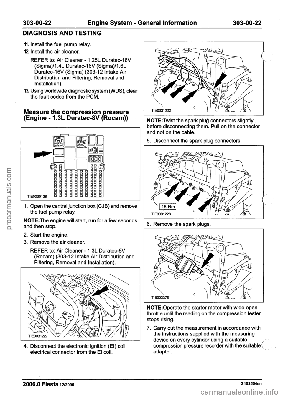
Measure the compression ressure
(Engine
- 1 .3L Duratec-8V P Rocam)) N0TE:Twist the spark plug connectors slightly
1. Open the
central junction box (CJB) and remove
the
fuel pump relay.
before disconnecting them. Pull on the connector
and not on the
cable.
5. Disconnect the spark plug connectors.
N0TE:The engine will start, run for a few seconds
and then stop. 6. Remove the spark plugs.
2. Start the engine.
3. Remove the air
cleaner.
REFER to: Air Cleaner - 1.3L Duratec-8V
(Rocam) (303-12 Intake Air Distribution and
Filtering, Removal and Installation).
N0TE:Operate the starter motor with wide open
throttle until the reading on the compression tester
stops rising.
7. Carry out the measurement in accordance with
the instructions
supplied with the measuring
device on every
cylinder using a suitable
4. Disconnect the electronic ignition (El) coil compression pressure recorder
with the suitable (:
electrical connector from the El coil. adapter.
2006.0 Fiesta 1212006 GI 52554en
procarmanuals.com
Page 445 of 1226
303-00-23 Engine System - General Information 303-00-23
DIAGNOSIS AND TESTING
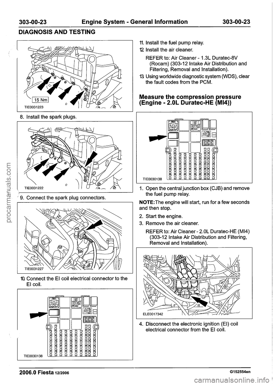
8. Install the spark plugs.
9. Connect the spark plug connectors.
1Q Connect the El coil electrical connector to the
El coil. 11.
Install the fuel pump relay.
I2 Install the air cleaner.
REFER to: Air Cleaner
- 1.3L Duratec-8V
(Rocam) (303-1 2 Intake Air Distribution and
Filtering, Removal and Installation).
13 Using worldwide diagnostic system (WDS), clear
the fault codes from the PCM.
Measure the compression ressure
(Engine
- 2.OL Duratec-HE PMI~))
1. Open the central junction box (CJB) and remove
the fuel pump relay.
N0TE:The engine will start, run for a few seconds
and then stop.
2. Start the engine.
3. Remove the air cleaner.
REFER to: Air Cleaner
- 2.OL Duratec-HE (M14)
(303-1 2 Intake Air Distribution and Filtering,
Removal and Installation).
4. Disconnect
the electronic ignition (El) coil
electrical connector from the El coil.
2006.0 Fiesta 1212006 GI 52554en
procarmanuals.com
Page 447 of 1226
303-00-25 Engine System - General Information 303-00-25
DIAGNOSIS AND TESTING
11. Install the fuel pump relay.
-. 12 Install the air cleaner.
REFER to: Air Cleaner
- 2.OL Duratec-HE (M14)
(303-12 Intake Air Distribution and Filtering,
Removal and Installation).
13 Reset the PCM fault memory.
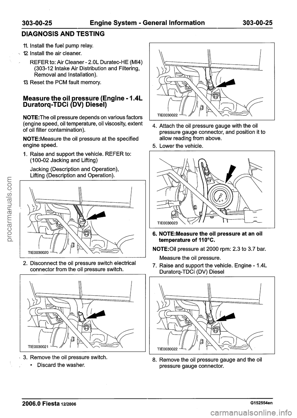
Measure the oil ressure (Engine - 1.4L
Duratorq-TDCi PDv) Diesel)
N0TE:The oil pressure depends on various factors
(engine speed, oil temperature, oil viscosity, extent
4m Attach the oil pressure gauge with the oil of oil filter contamination).
pressure gauge connector, and position it to
N0TE:Measure the oil pressure at the specified allow reading
from above.
engine speed.
5. Lower the vehicle.
I. Raise and support the vehicle. REFER to:
(1 00-02 Jacking and Lifting)
Jacking (Description and Operation),
Lifting (Description and Operation).
6. N0TE:Measure the oil pressure at an oil
temperature of 410°C.
N0TE:OiI pressure at 2000 rpm: 2.3 to 3.7 bar.
Measure the oil pressure.
2. Disconnect the oil pressure switch electrical
7. Raise and support the vehicle. Engine
- 1.4L connector from the oil pressure switch.
Duratorq-TDCi (DV) Diesel
3. Remove the oil pressure switch.
Discard the washer.
8. Remove the oil pressure gauge and the oil
pressure gauge connector.
2006.0 Fiesta 1212006 GI 52554en
procarmanuals.com
Page 478 of 1226
Engine - 1.25L Duratec-1 6V (Sigma)ll.4L
Duratec-1 6V (Sigma)/l .6L Duratec-1 6V (Sigma)
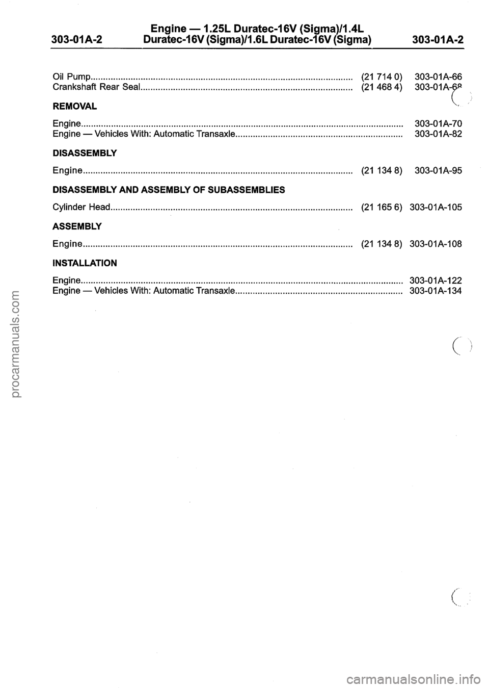
Oil Pump ...
Crankshaft
REMOVAL
. . . . . . . . . . . . . . . . . . . . . . . . . . . . . . . . . . . . . . . . . . . . . . . . . . . . . . . . . . . . . . . . . . . . . . . . . . . . . . . . . . . . . . . . . . . . . . . . . . . . . . (21 71 4 0) 303-01
A-66
Rear Seal.. . . . . . . . . . . . . . . . . . . . . . . . . . . . . . . . . . . . . . . . . . . . . . . . . . . . . . . . . . . . . . . . . . . . . . . . . . . . . . . . . . . . (21 468 4)
303-01
Engine ..... . . . . . . . . . . . . . . . . . . . . . . . . . . . . . . . . . . . . . . . . . . . . . . . . . . . . . . . . . . . . . . . . . . . . . . . . . . . . . . . . . . . . . . . . . . . . . . . . . . . . . . . . . . . . . . . . . . . . . . . . . . . . 303-01 A-70
Engine - Vehicles With: Automatic Transaxle ................................................................... 303-01A-82
DISASSEMBLY
Engine
........................................................................\
............................. (21 134 8) 303-01A-95
DISASSEMBLY AND ASSEMBLY OF SUBASSEMBLIES
Cylinder Head..
. . . . . . . . . . . . . . . . . . . . . . . . . . . . . . . . . . . . . . . . . . . . . . . . . . . . . . . . . . . . . . . . . . . . . . . . . . . . . . . . . . . . . . . . . . . . . . . (21 165 6) 303-01A-105
ASSEMBLY
Engine
........................................................................\
.................................... (21 134 8) 303-01A-108
INSTALLATION
Engine..
.... .. .... .................... . . . ............ ...... ....... . ...... . . ...... . . . . . . . . . . ....... . . . . ....... . . 303-01A-122
Engine - Vehicles With: Automatic Transaxle.. . . . . . . . . . . . . . . . . . . . . . . . . . . . . . . . . . . . . . . . . . . . . . . . . . . . . . . . . . . . . . . . . . 303-01 A-1 34
procarmanuals.com
Page 483 of 1226
Engine - 1.25L Duratec-1 6V (Sigma)ll.4L
Duratec-1 6V (Sigma)Il.GL Duratec-1 6V (Sigma)
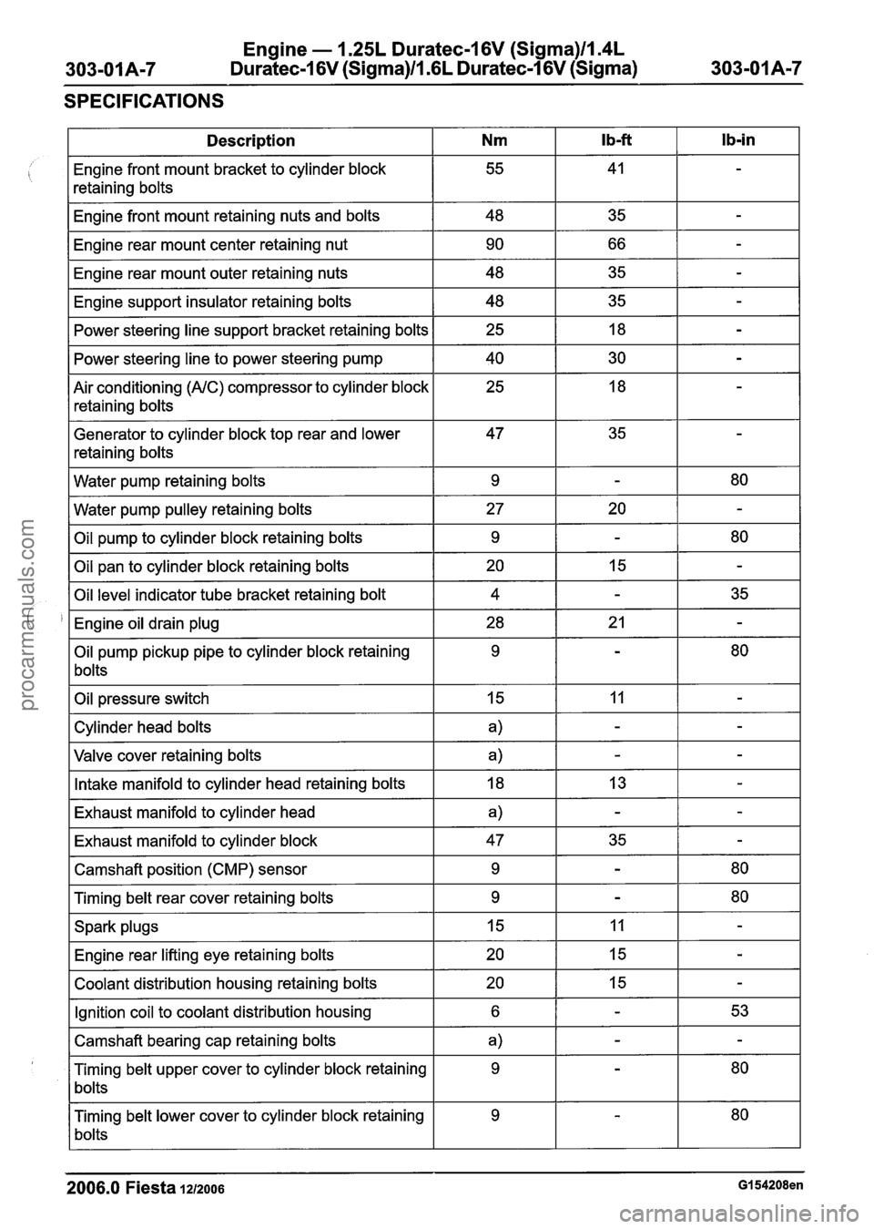
SPECIFICATIONS
2006.0 Fiesta 1212006 GI 54208en
Ib-in
-
-
-
-
-
-
-
-
-
80
-
80
-
35
-
80
-
-
-
-
-
-
80
80
-
-
-
53
-
80
80
Ib-ft
41
35
66
35 35 18
30
18
35
-
20
-
15
-
21
-
11
-
-
13
-
35
-
-
11
15
15
-
-
-
-
Description
Engine front mount bracket to cylinder block
retaining bolts
Engine front mount retaining nuts and bolts
Engine rear mount center retaining nut
Engine rear mount outer retaining nuts
Engine support insulator retaining bolts Power steering line support bracket retaining bolts
Power steering line to power steering pump
Air conditioning
(AIC) compressor to cylinder block
retaining bolts
Generator to cylinder block top rear and lower
retaining bolts
Water pump retaining bolts
Water pump pulley retaining bolts
Oil pump to cylinder block retaining bolts
Oil pan to cylinder block retaining bolts
Oil level indicator tube bracket retaining bolt
Engine oil drain plug
Oil pump pickup pipe to cylinder block retaining
bolts
Oil pressure switch
Cylinder head bolts
Valve cover retaining bolts
Intake manifold to cylinder head retaining bolts
Exhaust manifold to cylinder head
Exhaust manifold to cylinder block
Camshaft position (CMP) sensor
Timing belt rear cover retaining bolts
Spark plugs Engine rear lifting eye retaining bolts
Coolant distribution housing retaining bolts
Ignition coil to coolant distribution housing
Camshaft bearing cap retaining bolts
Timing belt upper cover to cylinder block retaining
bolts
Timing belt lower cover to cylinder block retaining
bolts
Nm
55
48 90
48
48 25
40 25
47
9
27 9
20 4
28 9
15
a)
a)
18
a)
47 9
9
15
20
20
6
a)
9
9
procarmanuals.com
Page 540 of 1226
Engine - 1.25L Duratec-1 6V (Sigma)lla4L
303-01 A-64 Duratec-1 6V (Sigma)ll .6L Duratec-1 6V (Sigma) 303-01 A-64
IN-VEHICLE REPAIR
Oil Pan(21 154 0)
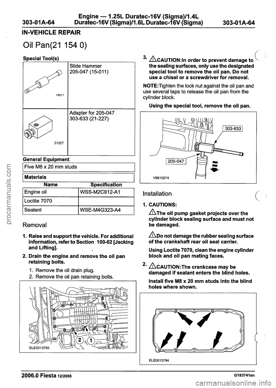
Special Tool(s)
Adapter for 205-047
303-633 (2
1 -227)
1501 1
General Equipment
Slide Hammer
205-047 (1 5-0 1 1 )
I Five M8 x 20 mm studs I
Materials
Name
S~ecification
3m CAUTION:^^ order to prevent damage to
the sealing surfaces, only use the designated
special tool to remove the oil pan. Do not
use a chisel or a screwdriver for removal.
N0TE:Tighten the lock nut against the oil pan and
use several taps to release the oil pan from the
cylinder block.
Using the special tool, remove the oil pan.
Installation
1. CAUTIONS:
n~he oil pump gasket projects over the
cylinder block sealing surface and must not
Removal be damaged.
I. Raise and support the vehicle. For additional ADO not damage the rubber sealing surface
information, refer to Section 100-02 [Jacking of
the crankshaft rear oil seal carrier.
and Lifting].
I Using Loctite 7070, clean the engine cylinder
2. Drain the engine and remove the oil pan block and
oil pan mating faces.
retaining bolts.
1. Remove the oil drain plug. 2m ~CAUTION:T~~ crankcase may be
damaged
if sealant enters the blind holes. 2. Remove the oil pan retaining bolts.
I I Install five M8 x 20 mm studs into the blind
holes where shown.
2006.0 Fiesta 1212006 GI 83741 en
procarmanuals.com
Page 542 of 1226
Engine - 1.25L Duratec-1 6V (Sigma)llm4L
303-01 A-66 Duratec-1 6V (Sigma)/l.GL Duratec-1 6V (Sigma) 303-01 A-66
IN-VEHICLE REPAIR
Oil Pump(21 714 0)
Special Tool(s)
Removal
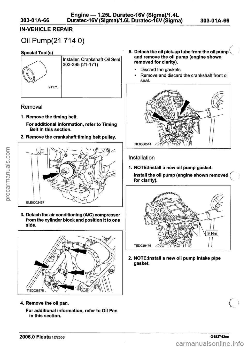
1. Remove the timing belt.
For additional information, refer to Timing
Belt in this section.
2. Remove the crankshaft timing belt pulley.
3. Detach the air conditioning (AIC) compressor
from the cylinder block and position
it to one
side.
4. Remove the oil pan.
For additional information, refer to Oil Pan
in this section.
5. Detach the oil pick-up tube from the oil pump
and remove the oil pump (engine shown
removed for clarity).
Discard the gaskets.
Remove and discard the crankshaft front oil
seal.
Installation
1. N0TE:lnstall a new oil pump gasket.
Install the oil pump (engine shown removed
for clarity).
2. N0TE:lnstall a new oil pump intake pipe
gasket.
2006.0 Fiesta 1212006 GI 83742en
procarmanuals.com