clock FORD FIESTA 2007 Workshop Manual
[x] Cancel search | Manufacturer: FORD, Model Year: 2007, Model line: FIESTA, Model: FORD FIESTA 2007Pages: 1226, PDF Size: 61.26 MB
Page 71 of 1226
100-04-15 Noise, Vibration and Harshness 100-04-15
DIAGNOSIS AND TESTING
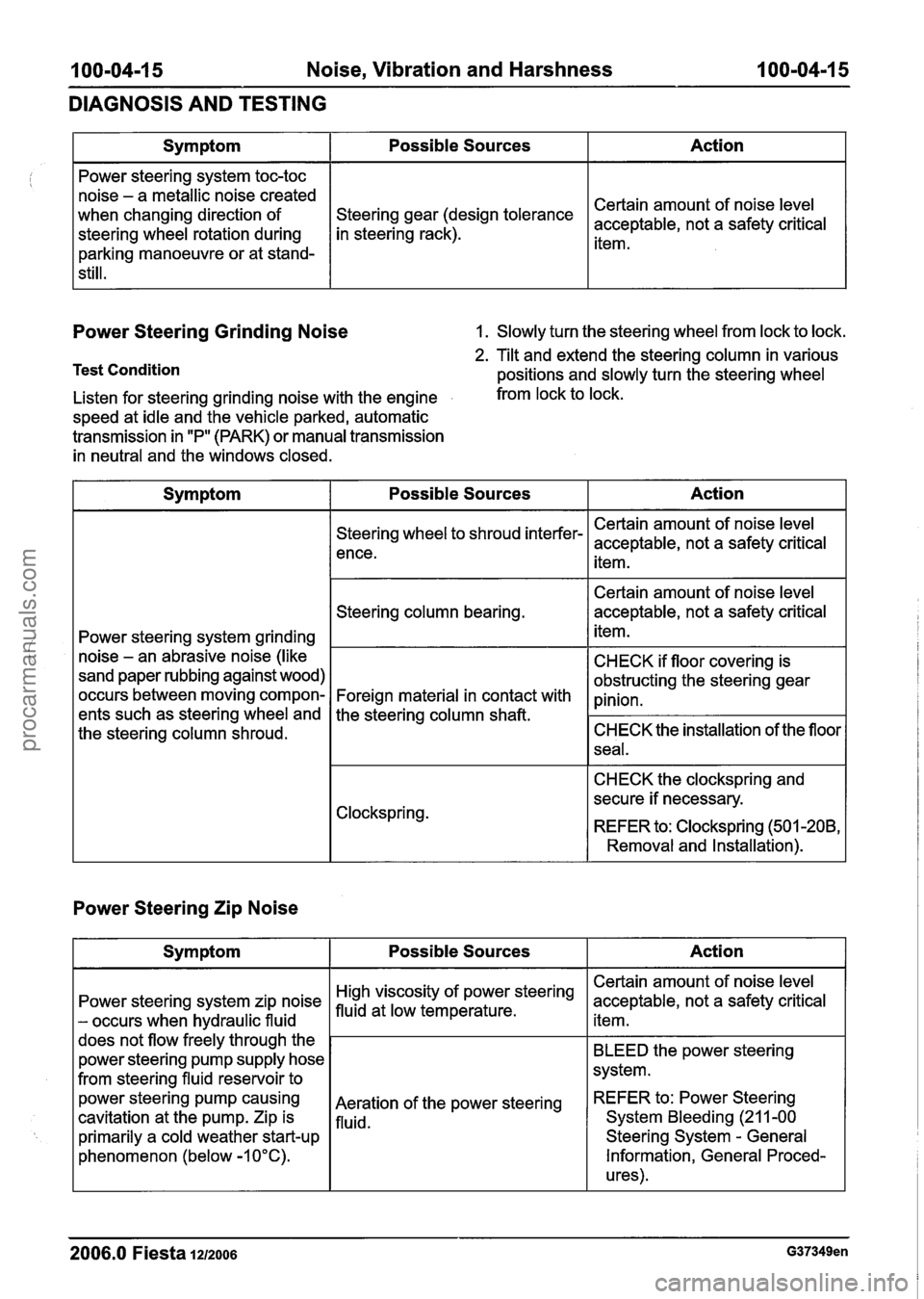
Power Steering Grinding Noise 1. Slowly turn the steering wheel from lock to lock.
Test Condition
Action
Certain amount of noise level
acceptable, not a safety critical
item.
Symptom
Power steering system toc-toc
noise - a metallic noise created
when changing direction of
steering wheel rotation during
parking manoeuvre or at stand-
still.
2. Tilt and extend the steering column in various
positions and slowly turn the steering wheel
Possible Sources
gear (design tolerance
in steering rack).
Listen for steering grinding noise with the engine from lock to lock.
speed at idle and the vehicle parked, automatic
transmission in "P" (PARK) or manual transmission
in neutral and the windows closed.
Power Steering Zip Noise
Symptom Possible Sources Action
Power steering system grinding
noise
- an abrasive noise (like
sand paper rubbing against wood)
occurs between moving compon-
ents such as steering wheel and
the steering column shroud.
2006.0 Fiesta 1212006 G37349en
Steering wheel to shroud interfer-
ence.
Steering column bearing.
Foreign material in contact with
the steering column
shaft.
Clockspring.
Action
Certain amount of noise level
acceptable, not a safety critical item.
BLEED the power steering
system.
REFER
to: Power Steering
System Bleeding
(21 1-00
Steering System
- General
Information, General Proced-
ures).
Symptom
Power steering system zip noise
- occurs when hydraulic fluid
does not flow freely through the
power steering pump supply hose
from steering fluid reservoir to
power steering
pump causing
cavitation
at the pump. Zip is
primarily a cold weather start-up
phenomenon (below -1 0°C). Certain amount
of noise level
acceptable, not a safety critical
item.
Certain amount of noise level
acceptable, not a safety critical
item.
CHECK if floor covering is
obstructing the steering gear
pinion.
CHECK the installation of the floor
seal.
CHECK the clockspring and
secure if necessary.
REFER to: Clockspring (501
-208,
Removal and Installation).
Possible Sources
steering
Aeration of the power steering
fluid.
procarmanuals.com
Page 97 of 1226
204-00-1 7 Suspension System - General Information 204-00-1 7
GENERAL PROCEDURES
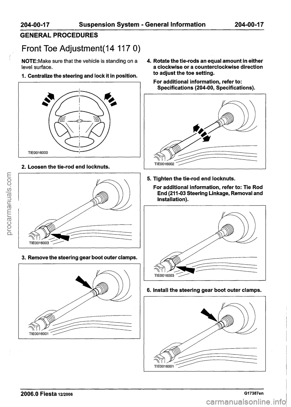
Front Toe Adjustment(l4 11 7 0)
I
N0TE:Make sure that the vehicle is standing on a 4. Rotate the tie-rods an equal amount in either
level surface. a clockwise or a counterclockwise direction
1. Centralize the steering and lock it in position. to
adjust the toe setting.
For additional information, refer to:
Specifications
(204-00, Specifications).
2. Loosen the tie-rod end locknuts.
3. Remove the steering gear boot outer clamps.
5. Tighten the tie-rod end locknuts.
For additional information, refer to: Tie Rod
End (21
1-03 Steering Linkage, Removal and
Installation).
6. Install the steering gear boot outer clamps.
2006.0 Fiesta 1212006 GI 7387en
procarmanuals.com
Page 141 of 1226
204-02-1 9 Rear Suspension 204-02-1 9
REMOVAL AND INSTALLATION
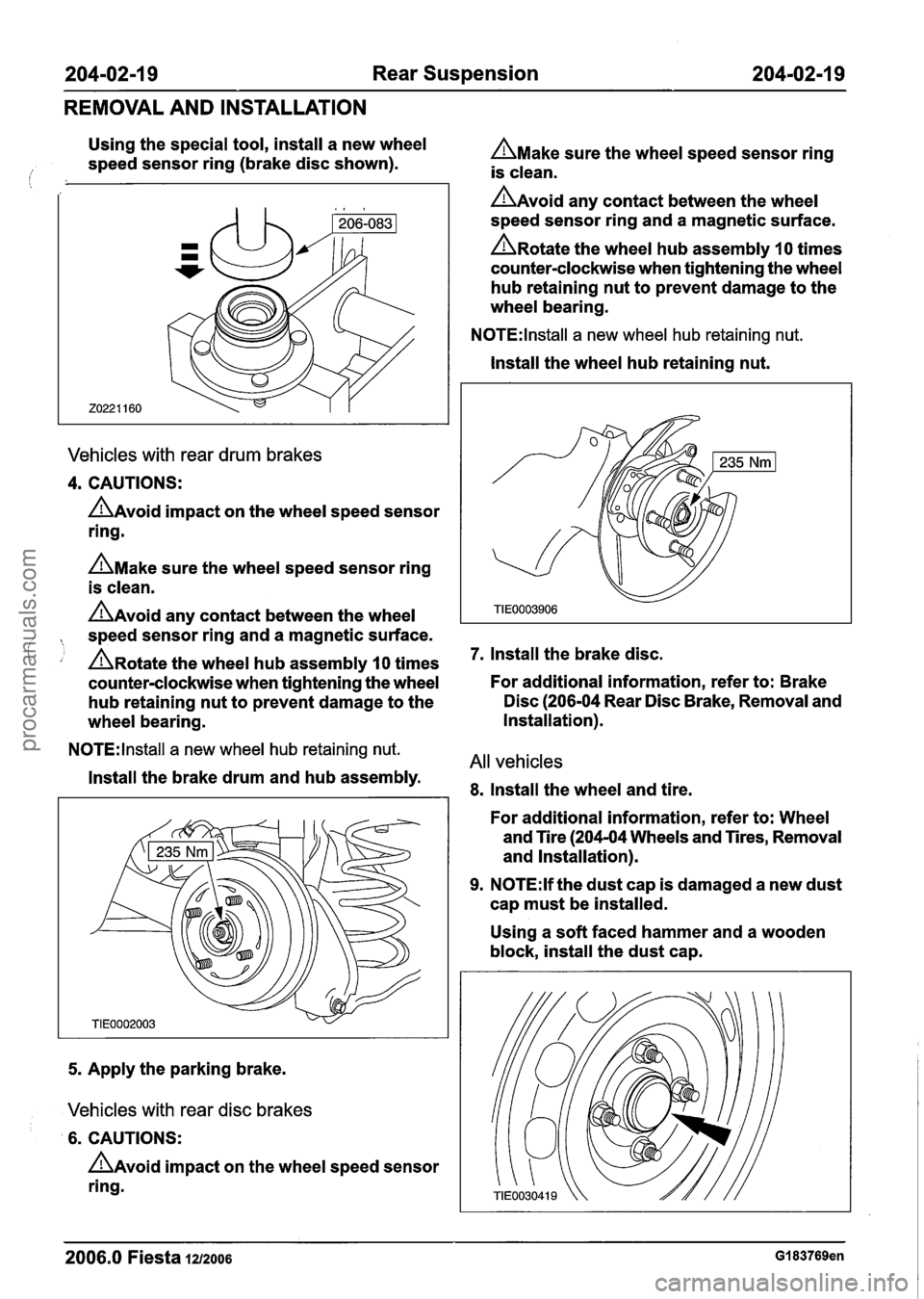
Using the special tool, install a new wheel
speed sensor ring (brake disc shown).
Vehicles with rear drum brakes
4. CAUTIONS:
AAvoid impact on the wheel speed sensor
ring.
AMake sure the wheel speed sensor ring
is clean.
AAvoid any contact between the wheel
, speed sensor ring and a magnetic surface.
' , A~otate the wheel hub assembly 10 times
counter-clockwise when tightening the wheel
hub retaining nut to prevent damage to the
wheel bearing.
N0TE:lnstall a new wheel hub retaining nut.
Install the brake drum and hub assembly.
5. Apply the parking brake.
Vehicles with rear disc brakes
6. CAUTIONS:
AAvoid impact on the wheel speed sensor
ring.
AMake sure the wheel speed sensor ring
is clean.
AAvoid any contact between the wheel
speed sensor ring and a magnetic surface.
A~otate the wheel hub assembly 10 times
counter-clockwise when tightening the wheel
hub retaining nut to prevent damage to the
wheel bearing.
N0TE:lnstall a new wheel hub retaining nut.
Install the wheel hub retaining nut.
7. lnstall the brake disc.
For additional information, refer to: Brake
Disc (206-04 Rear Disc Brake, Removal and
Installation).
All vehicles
8. Install the wheel and tire.
For additional information, refer to: Wheel
and Tire (204-04 Wheels and Tires, Removal
and Installation).
9. N0TE:lf the dust cap is damaged a new dust
cap must be installed.
Using a soft faced hammer and a wooden
block, install the dust cap.
2006.0 Fiesta 1212006 GI 83769en
procarmanuals.com
Page 297 of 1226
Anti-Lock Control
REMOVAL AND INSTALLATION
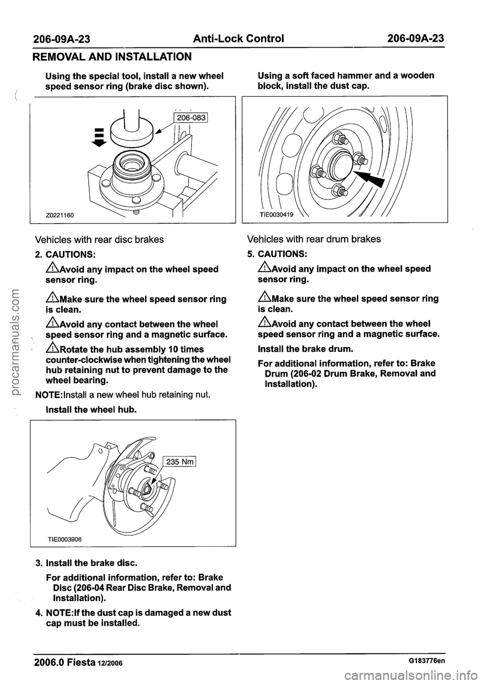
Using the special tool, install a new wheel Using
a soft faced hammer and a wooden
/ speed sensor ring (brake disc shown). block,
install the dust cap.
Vehicles with rear disc brakes
2. CAUTIONS:
AAvoid any impact on the wheel speed
sensor ring.
n~ake sure the wheel speed sensor ring
is clean.
A~void any contact between the wheel
, speed sensor ring and a magnetic surface.
( , A~otate the hub assembly 10 times
counterclockwise when tightening the wheel
hub retaining nut to prevent damage to the
wheel bearing.
Vehicles with rear drum brakes
5. CAUTIONS:
AAvoid any impact on the wheel speed
sensor ring.
AMake sure the wheel speed sensor ring
is clean.
AAvoid any contact between the wheel
speed sensor ring and a magnetic surface.
Install the brake drum.
For additional information, refer to: Brake
Drum (206-02 Drum Brake, Removal and
Installation).
N0TE:lnstall a new wheel hub retaining nut.
Install the wheel hub.
3. Install the brake disc.
For additional information, refer to: Brake
Disc (206-04 Rear Disc Brake, Removal and
Installation).
4.
N0TE:lf the dust cap is damaged a new dust
cap must be installed.
2006.0 Fiesta 1212006 GI 83776en
procarmanuals.com
Page 316 of 1226
206-096-1 0 Anti-Lock Control - Stability Assist 206-096-1 0
REMOVAL AND INSTALLATION
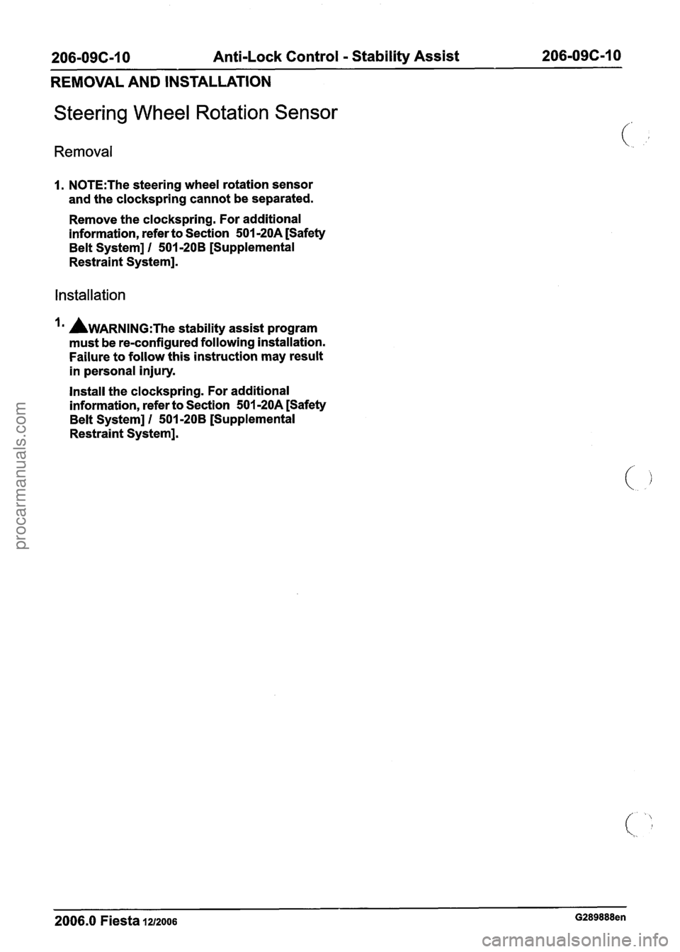
Steering Wheel Rotation Sensor
Removal
1. N0TE:The steering wheel rotation sensor
and the clockspring cannot be separated.
Remove the clockspring. For additional
information, refer to Section
501-20A [Safety
Belt System]
I 501-20B [Supplemental
Restraint System].
Installation
AWARNING:T~~ stability assist program
must be re-configured following installation.
Failure to follow this instruction may result
in personal injury.
Install the clockspring. For additional
information, refer to Section
501 -20A [Safety
Belt System]
1 501-208 [Supplemental
Restraint System].
2006.0 Fiesta 1212006 G289888en
procarmanuals.com
Page 336 of 1226
21 1-00-1 6 Steering System - General Information 21 I -00-1 6
DIAGNOSIS AND TESTING
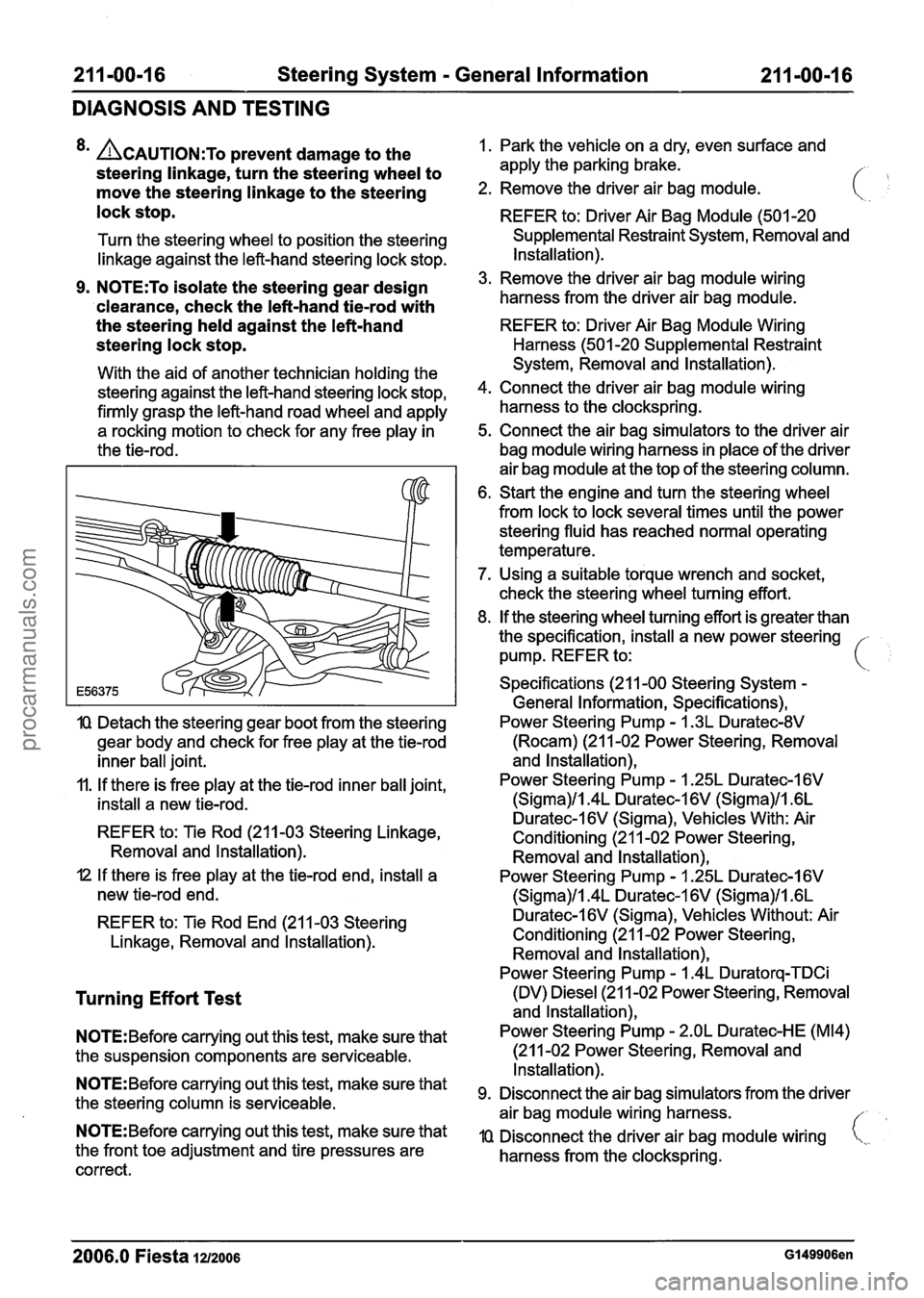
8m ACAUTION:T~ prevent damage to the
steering linkage, turn the steering wheel to
move the steering linkage to the steering
lock stop.
Turn the steering wheel to position the steering
linkage against the left-hand steering lock stop.
9. N0TE:To isolate the steering gear design
'clearance, check the left-hand
tiemrod with
the steering held against the left-hand
steering lock stop.
With the aid of another technician holding the
steering against the left-hand steering lock stop,
firmly grasp the left-hand road wheel and apply
a rocking motion to check for any free play in
the tie-rod.
IQ Detach the steering gear boot from the steering
gear body and check for free play at the tie-rod
inner ball joint.
11. If there is free play at the tie-rod inner ball joint,
install a new tie-rod.
REFER to: Tie Rod (211-03 Steering Linkage,
Removal and lnstallation).
I2 If there is free play at the tie-rod end, install a
new tie-rod end.
REFER to: Tie Rod End (21 1-03 Steering
Linkage, Removal and lnstallation).
Turning Effort Test
N0TE:Before carrying out this test, make sure that
the suspension components are serviceable.
N0TE:Before carrying out this test, make sure that
the steering column is serviceable.
N0TE:Before carrying out this test, make sure that
the front toe adjustment and tire pressures are
correct. 1.
Park the vehicle on a dry, even surface and
apply the parking brake.
/- ,
2. Remove the driver air bag module.
REFER to: Driver Air Bag Module (501 -20
Supplemental Restraint System, Removal and
Installation).
3. Remove the driver air bag module wiring
harness from the driver air bag module.
REFER to: Driver Air Bag Module Wiring
Harness (501 -20 Supplemental Restraint
System, Removal and Installation).
4. Connect the driver air bag module wiring
harness to the clockspring.
5. Connect the air bag simulators to the driver air
bag module wiring harness in place of the driver
air bag module at the top of the steering column.
6. Start the engine and turn the steering wheel
from lock to lock several times until the power
steering fluid has reached normal operating
temperature.
7. Using a suitable torque wrench and socket,
check the steering wheel turning effort.
8. If the steering wheel turning effort is greater than
the specification, install a new power steering -
pump. REFER to: i
Specifications (21 1-00 Steering System -
General Information, Specifications),
Power Steering Pump
- I .3L Duratec-8V
(Rocam) (21 1-02 Power Steering, Removal
and lnstallation),
Power Steering Pump
- 1.25L Duratec-1 6V
(Sigma)/l.4L Duratec-1 6V (Sigma)/l .6L
Duratec-l6V (Sigma), Vehicles With: Air
Conditioning (21 1-02 Power Steering,
Removal and lnstallation),
Power Steering Pump
- I .25L Duratec-I 6V
(Sigma)/l.4L Duratec-1 6V (Sigma)/l .6L
Duratec-I 6V (Sigma), Vehicles Without: Air
Conditioning (21 1-02 Power Steering, Removal and lnstallation),
Power Steering Pump
- 1.4L Duratorq-TDCi
(DV) Diesel (21 1-02 Power Steering, Removal
and lnstallation),
Power Steering Pump
- 2.OL Duratec-HE (M14)
(21 1-02 Power Steering, Removal and
Installation).
Disconnect the air bag simulators from the driver
air bag module wiring harness.
//
IQ Disconnect the driver air bag module wiring i,,.
harness from the clockspring.
2006.0 Fiesta 1212006 GI 49906en
procarmanuals.com
Page 337 of 1226
211 -00-1 7 Steering System - General Information 21 1 -00-1 7
DIAGNOSIS AND TESTING
11. Install a new driver air bag module wiring
harness to the drive air bag module. If the
movement is not smooth or resistance
is felt, renew the steering column.
REFER to: Driver Air Bag Module Wiring REFER
to: Steering Column (21 1-04 Steering
Harness (501 -20 Supplemental Restraint Column,
Removal and Installation).
System, Removal and lnstallation).
12 Install the driver air bag module.
3. Hold both of the steering column shaft universal
joint yokes and then twist them clockwise and
REFER to: Driver Air Bag Module (501-20 counterclockwise.
Supplemental Restraint System, Removal and If
any movement is felt, install a new steering
installation). column.
REFER to: Steering Column (21 1-04 Steering
Column, Removal and lnstallation).
Steering Column Shaft Universal Joint
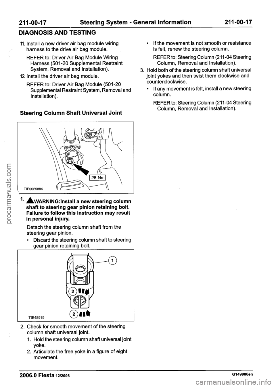
la AwARNING:~~~~~~~ a new steering column
shaft to steering gear pinion retaining bolt.
Failure to follow this instruction may result
in personal injury.
Detach the steering column shaft from the
steering gear pinion.
Discard the steering column shaft to steering
gear pinion retaining bolt.
2. Check for smooth movement of the steering
column shaft universal joint.
1. Hold the steering column shaft universal joint
yoke.
2. Articulate the free yoke in a figure of eight
movement.
2006.0 Fiesta 1212006 GI 49906en
procarmanuals.com
Page 414 of 1226
2 1 1 -04-6 Steering Column 21 1 -04-6
REMOVAL AND INSTALLATION
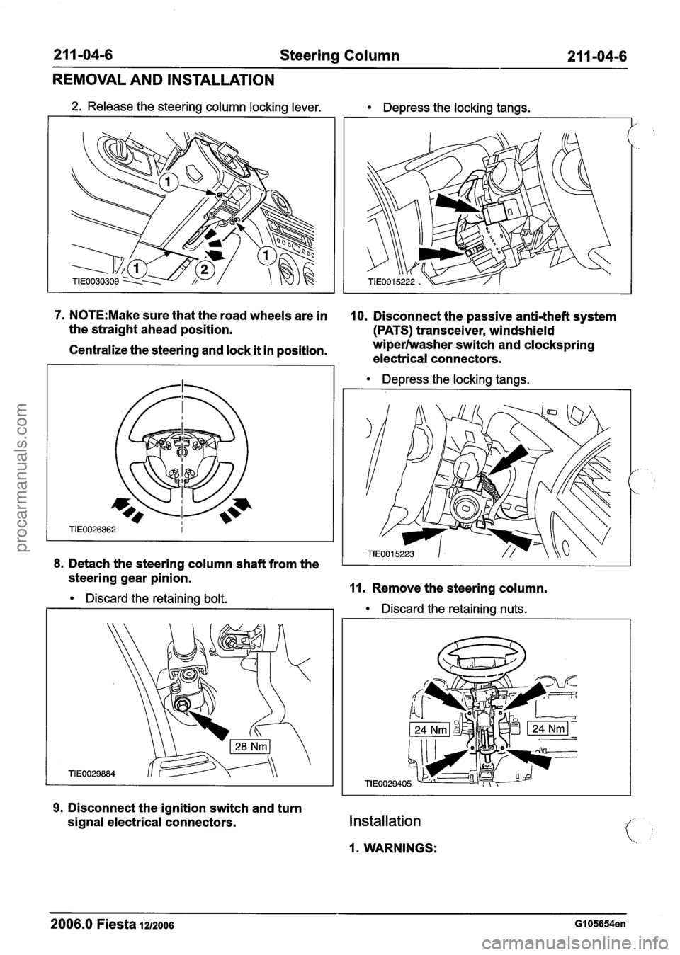
2. Release the steering column locking lever. Depress the locking tangs.
1--
7. N0TE:Make sure that the road wheels are in 10. Disconnect the passive anti-theft system
the straight ahead position.
(PATS) transceiver, windshield
Centralize the steering and lock it in position. wiperlwasher
switch and clockspring
electrical connectors.
Depress the locking tangs.
8. Detach the steering column shaft from the
steering gear pinion.
Discard the retaining bolt. 11. Remove the steering column.
Discard the retaining nuts.
9. Disconnect the ignition switch and turn
signal electrical connectors.
Installation
1. WARNINGS:
2006.0 Fiesta 1212006 GI 05654en
procarmanuals.com
Page 416 of 1226
2 1 1 -04-8 Steering Column 2 1 1 -04-8
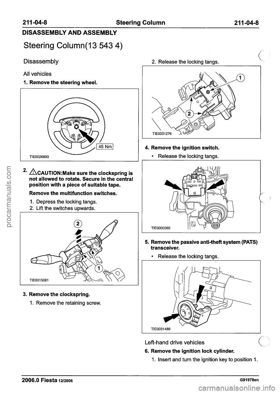
DISASSEMBLY AND ASSEMBLY
Steering Column(l3 543 4)
Disassembly 2. Release the locking tangs. (:
All vehicles
1. Remove the steering wheel.
4. Remove the ignition switch.
Release the locking tangs.
3. Remove the clockspring.
1. Remove the retaining screw.
*' ACAUTION:M~~~ sure the clockspring is
not allowed to rotate. Secure in the central
position with a piece of suitable tape.
Remove the multifunction switches.
1. Depress the locking tangs.
2. Lift the switches upwards.
5. Remove the passive anti-theft system (PATS)
transceiver.
1
TIE0000392
Release the locking tangs.
Left-hand drive vehicles
6. Remove the ignition lock cylinder.
1. Insert and turn the ignition key to position 1.
2006.0 Fiesta 12/2006 G91978en
procarmanuals.com
Page 517 of 1226
Engine - 1.25L Dura
303-01 A-41 Duratec-I 6V (Sigma)ll.~
:eel 6V (Sigma)llI4L
iL Duratec-1 6V (Sigma) 303-01 A-41
IN-VEHICLE REPAIR
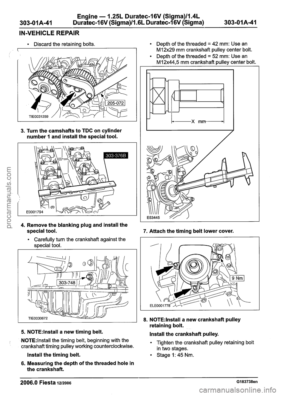
Discard the retaining bolts.
3. Turn the camshafts to TDC on cylinder
number
1 and install the special tool.
4. Remove the blanking plug and install the
special tool.
Carefully turn the crankshaft against the
special tool.
5.
N0TE:lnstall a new timing belt.
N0TE:lnstall the timing belt, beginning with the
crankshaft timing pulley working counterclockwise.
Install the timing belt.
6. Measuring the depth of the threaded hole in
the crankshaft.
Depth of the threaded = 42 mm: Use an
M12x29 mm crankshaft pulley center bolt.
Depth of the threaded
= 52 mm: Use an
MI 2x44,5 mm crankshaft pulley center bolt.
7. Attach the timing belt lower cover.
8. N0TE:lnstall a new crankshaft pulley
retaining bolt.
Install the crankshaft pulley.
Tighten the crankshaft pulley retaining bolt
in two stages.
Stage1:45Nm.
2006.0 Fiesta 1212006 GI 83738en
procarmanuals.com