clock FORD FIESTA 2007 User Guide
[x] Cancel search | Manufacturer: FORD, Model Year: 2007, Model line: FIESTA, Model: FORD FIESTA 2007Pages: 1226, PDF Size: 61.26 MB
Page 518 of 1226

Engine - 1.25L Duratec-1 6V (Sigma)ll.4L
303-01 A-42 Duratec-1 6V (Sigma)/lm6L Duratec-1 6V (Sigma) 303-01 A-42
IN-VEHICLE REPAIR
Stage 2: 90 degrees.
Engines with eccentric cam timing belt
tensioner
Tension the timing belt by turning the
tensioner clockwise until the arrow points in
line with the center of the rectangular hole
and tighten the bolt.
9. Install the timing belt tensioner. Vehicles built 0912003 onwards
10. Tension the timing belt.
Tension the timing belt by turning the
tensioner counterclockwise until the arrow
points at the mark and tighten the bolt.
I*' AWARNING:D~ not remove the special
tool, until the timing belt is correctly
positioned. Failure to follow this instruction
may result in personal injury, or may
damage the timing belt tensioner.
Install the timing belt tensioner.
/--
13. Tension the timing belt.
Remove the special tool.
Engines with slotted bracket timing belt
tensioner
I I. Install the timing belt tensioner and tension
the timing belt.
Screw in the bolts finger tight.
2006.0 Fiesta 1212006 GI 83738en
procarmanuals.com
Page 555 of 1226
Engine - 1.25L Duratec-I 6V (Sigma)llm4L
303-01A-79 Duratec-1 6V (Sigma)/l .6L Duratec-1 6V (Sigma) 303-01 A-79
REMOVAL
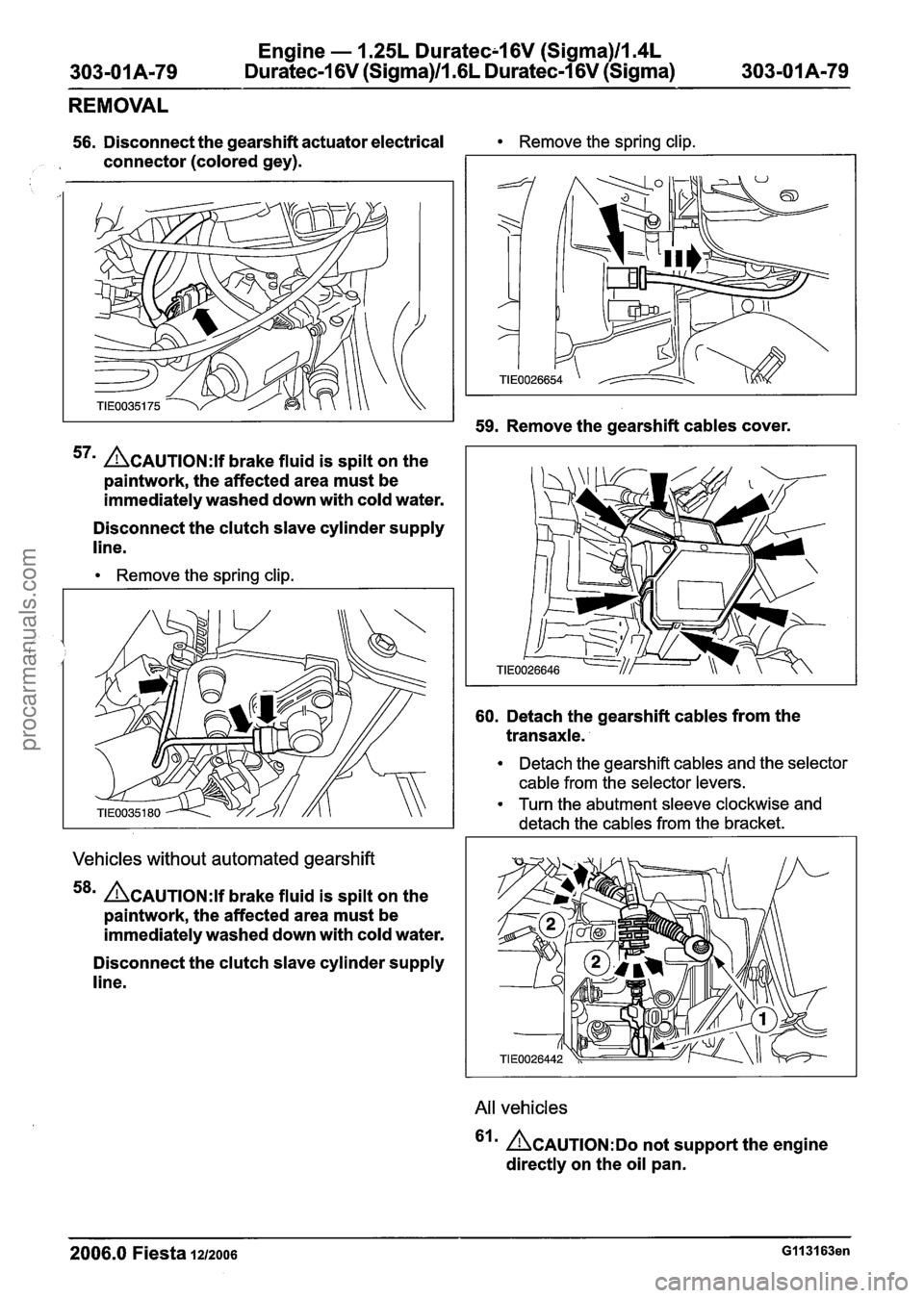
56. Disconnect the gearshift actuator electrical Remove the spring clip.
, connector (colored gey).
59. Remove the gearshift cables cover.
57m ACAUTION:I brake fluid is spilt on the
paintwork, the affected area must be
immediately washed down with cold water.
Disconnect the clutch slave cylinder supply
line.
Remove the spring clip.
Vehicles without automated gearshift
58' ACAUTION:~ brake fluid is spilt on the
paintwork, the affected area must be
immediately washed down with cold water.
Disconnect the clutch slave cylinder supply
line.
60. Detach the gearshift cables from the
transaxle.
Detach the gearshift cables and the selector
cable from the selector levers.
Turn the abutment sleeve clockwise and
detach the cables from the bracket.
All vehicles
'Irn ~CAUTION:DO not support the engine
directly on the oil pan.
2006.0 Fiesta 12/2oo6 G113163en
procarmanuals.com
Page 588 of 1226
303-01 A-I 12
Engine - 1.25L Duratec-1 6V (Sigma)ll.4L
Duratec-1 6V (Sigma)/lm6L Duratec-1 6V (Sigma)
ASSEMBLY
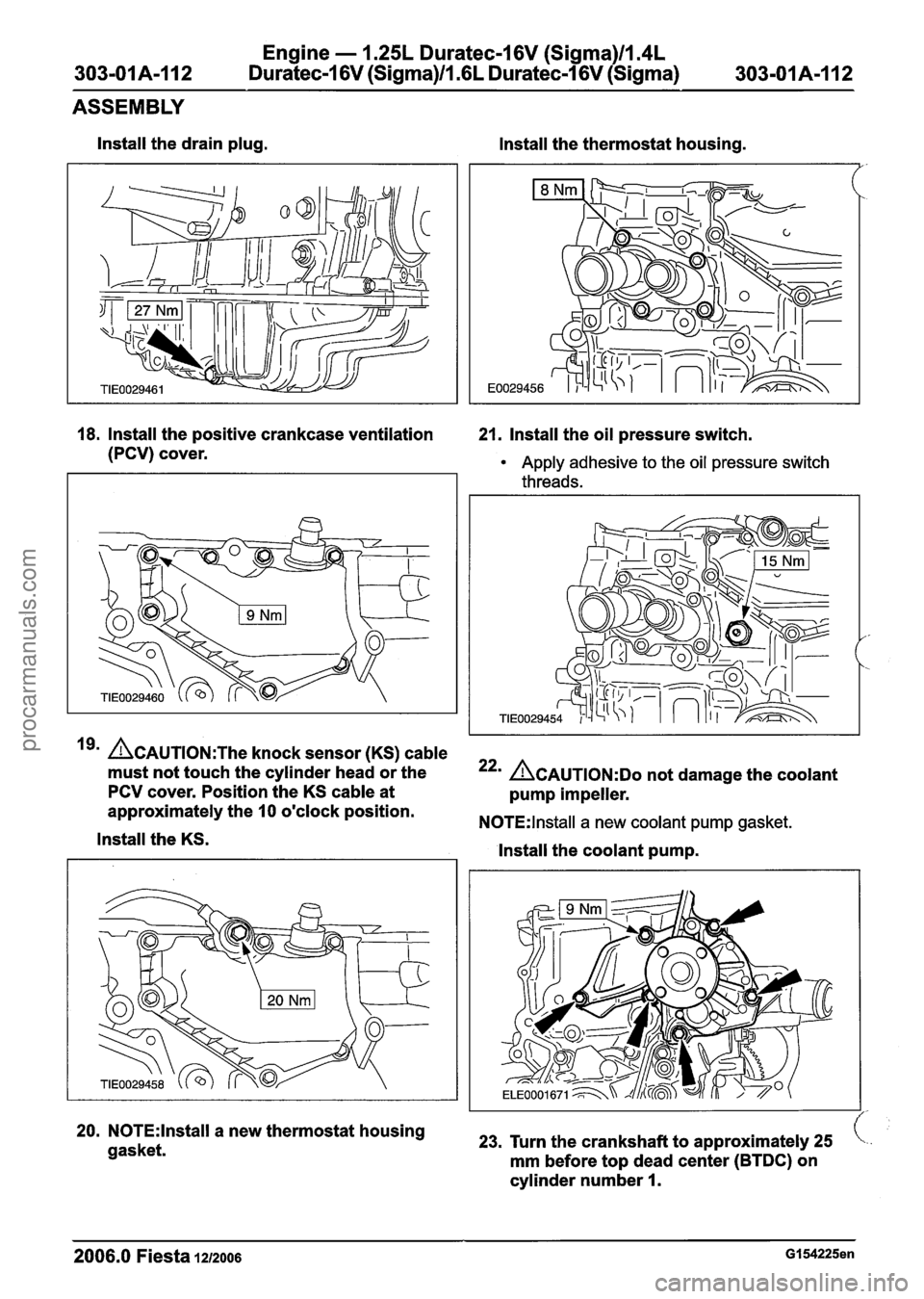
lnstall the drain plug.
lnstall the thermostat housing.
18. Install the positive crankcase ventilation 21. Install the oil pressure switch.
(PCV) cover.
Apply adhesive to the oil pressure switch
threads.
19' ~CAUTION:T~~ knock sensor (KS) cable
must not touch the cylinder head or the
PCV cover. Position the KS cable at
approximately the
10 o'clock position.
lnstall the KS.
20. N0TE:lnstall a new thermostat housing
gasket.
22' ACAUTION:D~ not damage the coolant
pump impeller.
N0TE:lnstall a new coolant pump gasket.
lnstall the coolant pump.
23, Turn the crankshaft to approximately 25
mm before top dead center (BTDC) on
cylinder number
I.
2006.0 Fiesta 1212006 GI 54225en
procarmanuals.com
Page 591 of 1226
Engine - 1.25L Dura
303-01A-115 Duratec-1 6V (Sigma)ll.(
tec-16V (Sigma)ll.4L
iL Duratec-1 6V (Sigma) 303-01A-I15
ASSEMBLY
Install the camshaft timing pulleys.
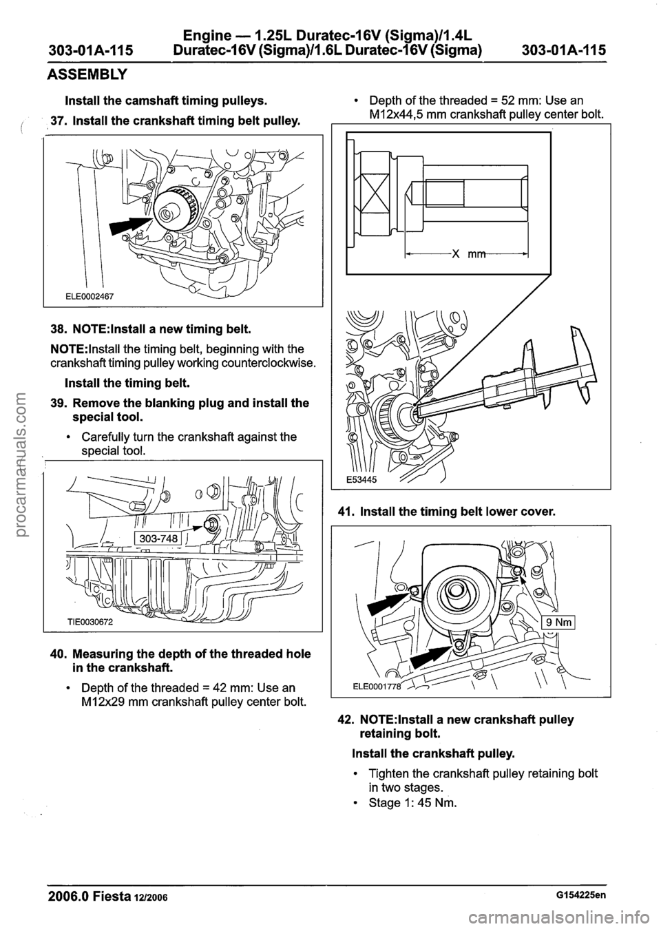
io 37. Install the crankshaft timing belt pulley.
38. N0TE:lnstall a new timing belt.
N0TE:lnstall the timing belt, beginning with the
crankshaft timing pulley working counterclockwise.
Install the timing belt.
39. Remove the blanking plug and install the
special tool.
Carefully turn the crankshaft against the
,I special tool.
40. Measuring the depth of the threaded hole
in the crankshaft.
Depth of the threaded = 42 mm: Use an
MI 2x29 mm crankshaft pulley center bolt. Depth
of the threaded
= 52 mm: Use an
M12x44,5 mm crankshaft pulley center bolt.
41. Install the timing belt lower cover.
42. N0TE:lnstall a new crankshaft pulley
retaining bolt.
Install the crankshaft pulley.
Tighten the crankshaft pulley retaining bolt
in two stages.
Stage 1: 45 Nm.
2006.0 Fiesta 1212006 GI 54225en
procarmanuals.com
Page 592 of 1226
Engine - 1.25L Duratec-1 6V (Sigma)ll.4L
303-01 A-I 16 Duratec-1 6V (Sigma)/l .6L Duratec-1 6V (Sigma)
303-01 A-1 16
ASSEMBLY
Stage 2: 90 degrees.
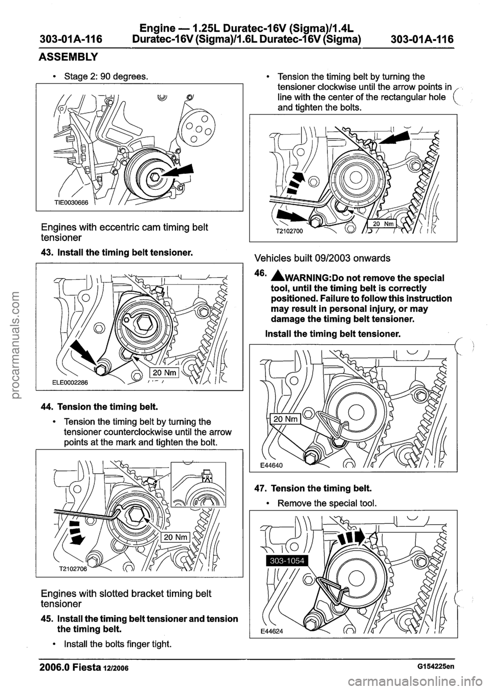
Engines with eccentric cam timing belt
tensioner
43. Install the timing belt tensioner.
44. Tension the timing belt.
Tension the timing belt by turning the
tensioner counterclockwise until the arrow
points at the mark and tighten the bolt.
Engines with slotted bracket timing belt
tensioner
45. Install the timing belt tensioner and tension
the timing belt.
Install the bolts finger tight.
Tension the timing belt by turning the
tensioner clockwise until the arrow points in
line with the center of the rectangular hole
(
and tighten the bolts.
Vehicles built 0912003 onwards
46' AWARNING:D~ not remove the special
tool, until the timing belt is correctly
positioned. Failure to follow this instruction
may result in personal injury, or may
damage the timing belt tensioner.
Install the timing belt tensioner.
f,
47. Tension the timing belt.
Remove the special tool.
2006.0 Fiesta 1212006 GI 54225en
procarmanuals.com
Page 603 of 1226
Engine - 1.25L Duratec-1 6V (Sigma)ll.4L
303-01 A-I 27 Duratec-1 6V (Sigma)ll .6L Duratec-1 6V (Sigma)
303-01 A-I 27
INSTALLATION
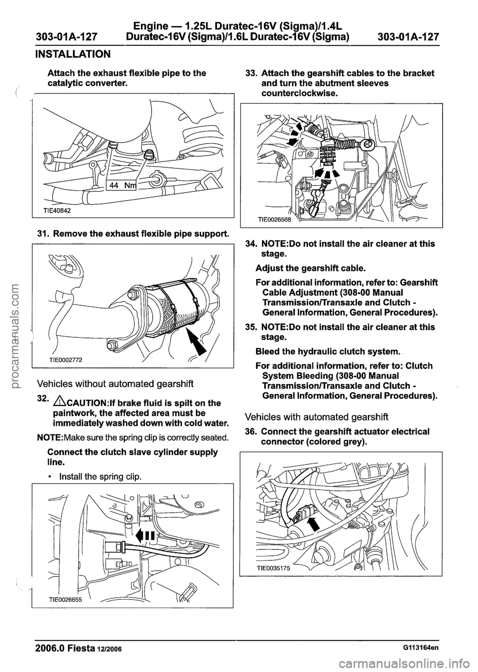
Attach the exhaust flexible pipe to the
33. Attach the gearshift cables to the bracket
catalytic converter.
and turn the abutment sleeves
counterclockwise.
31. Remove the exhaust flexible pipe support.
Vehicles without automated gearshift
32m ACAUTION:H brake fluid is spilt on the
paintwork, the affected area must be
immediately washed down with cold water.
N0TE:Make sure the spring clip is correctly seated.
Connect the clutch slave cylinder supply
line.
Install the spring clip.
34. N0TE:Do not install the air cleaner at this
stage.
Adjust the gearshift cable.
For additional information, refer to: Gearshift Cable Adjustment (308-00 Manual
Transmission/Transaxle and Clutch
General Information, General Procedures).
35.
N0TE:Do not install the air cleaner at this
stage.
Bleed the hydraulic clutch system.
For additional information, refer to: Clutch
System Bleeding (308-00 Manual
Transmission/Transaxle and Clutch -
General Information, General Procedures).
Vehicles with automated gearshift
36. Connect the gearshift actuator electrical
connector (colored grey).
2006.0 Fiesta 1212006
procarmanuals.com
Page 702 of 1226
303-01 B-80 Engine - 2.OL Duratec-HE (M14) 303-01 B-80
REMOVAL
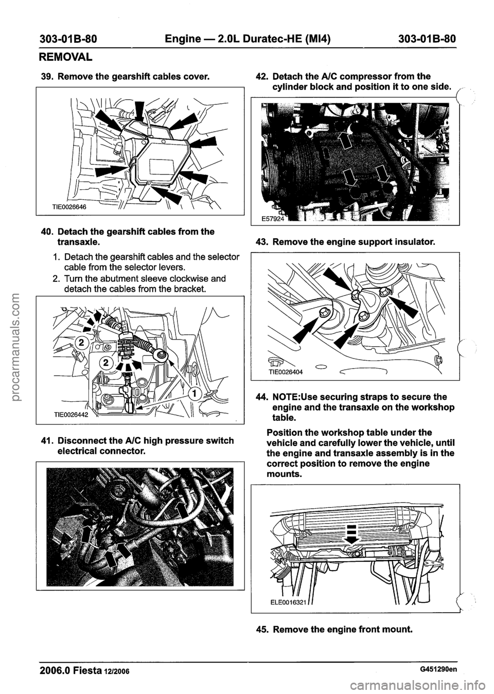
39. Remove the gearshift cables cover. 42. Detach the NC compressor from the
cylinder block and position
it to one side. /-
40. Detach the gearshift cables from the
transaxle. 43.
Remove the engine support insulator.
1. Detach the gearshift cables and the selector
cable from the selector levers.
2. Turn the abutment sleeve clockwise and
detach the cables from the bracket.
44. N0TE:Use securing straps to secure the
engine and the transaxle on the workshop
table.
Position the workshop table under the
41. Disconnect the NC high pressure switch
vehicle and carefully lower the vehicle, until
electrical connector.
the engine and transaxle assembly is in the
correct position to remove the engine
mounts.
45. Remove the engine front mount.
2006.0 Fiesta 1212006 G451290en
procarmanuals.com
Page 719 of 1226
303-01 B-97 Engine - 2.OL Duratec-HE (M14) 303-01 B-97
ASSEMBLY
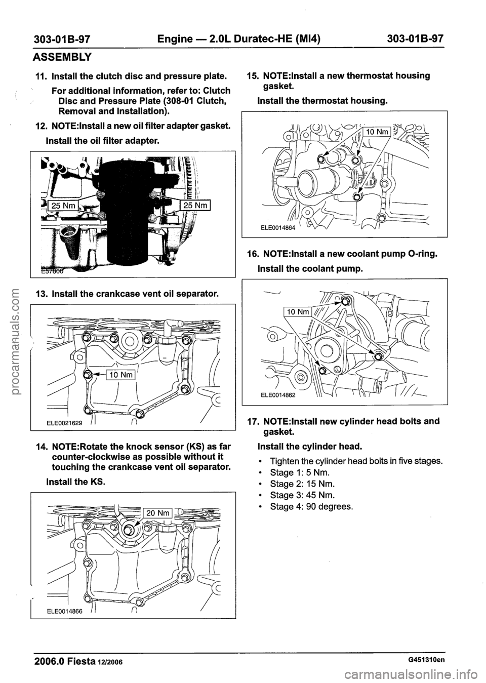
11. lnstall the clutch disc and pressure plate. 15. N0TE:lnstall a
new thermostat housing
'. For additional information, refer to: Clutch gasket.
Disc and Pressure Plate (308-01 Clutch, Install
the thermostat housing.
Removal and Installation).
12.
N0TE:lnstall a new oil filter adapter gasket.
lnstall the oil filter adapter.
13. lnstall the crankcase vent oil separator. 16.
N0TE:lnstall a
new coolant pump O-ring.
lnstall the coolant pump.
17.
N0TE:lnstall new cylinder head bolts and
gasket.
14.
N0TE:Rotate the knock sensor (KS) as far Install
the cylinder head.
counter-clockwise as possible without
it Tighten the cylinder head bolts in five stages. touching the crankcase vent oil separator. Stage I: 5 Nm.
lnstall the KS. stage 2: 15 Nm.
Stage 3: 45 Nm.
Stage 4: 90 degrees.
2006.0 Fiesta 1212006 G451310en
procarmanuals.com
Page 735 of 1226
303-01 B-I 13 Engine - 2.OL Duratec-HE (M14) 303-01 B-113
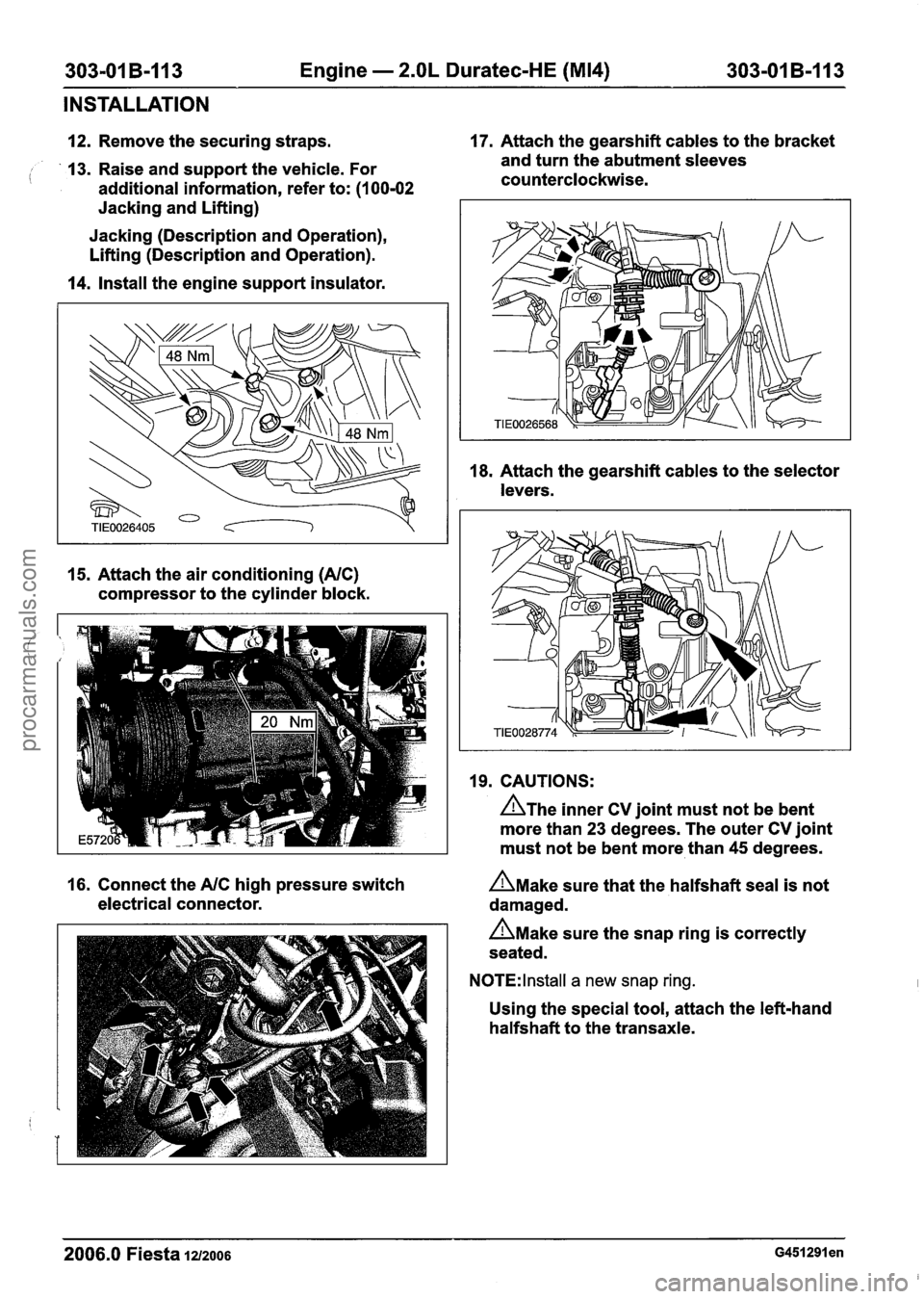
INSTALLATION
12. Remove the securing straps. 17.
Attach the gearshift cables to the bracket
13. Raise and support the vehicle. For and
turn the abutment sleeves
( additional information, refer to: (I 00-02 counterclockwise.
Jacking and Lifting)
Jacking (Description and Operation),
Lifting (Description and Operation).
14. Install the engine support insulator.
15. Attach the air conditioning (NC)
compressor to the cylinder block. 18.
Attach the gearshift cables to the selector
levers.
19. CAUTIONS:
A~he inner CV joint must not be bent
more than 23 degrees. The outer CV joint
must not be bent more than 45 degrees.
16. Connect the
NC high pressure switch n~ake sure that the halfshaft seal is not
electrical connector. damaged.
n~ake sure the snap ring is correctly
seated.
N0TE:lnstall a new snap ring.
Using the special tool, attach the left-hand
halfshaft to the transaxle.
2006.0 Fiesta 1212006 ~451291 en
procarmanuals.com
Page 758 of 1226
Engine Cooling - 1.3L Duratec-8V
(Rocam)ll.25L Duratec-I 6V (Sigma)ll.4L
303-03A-16 Duratec-1 6V (Sigma)/l .6L Duratec-1 6V (Sigma) 303-03A-16
DIAGNOSIS AND TESTING
Component Tests
Pressure Test
A WARNING:When releasing the system
pressure, cover the expansion tank cap
with a thick cloth to prevent the possibility
of coolant scalding, Failure to follow this
instruction may result in personal injury.
1. Remove the coolant expansion tank cap.
2.
Install the special tools to the coolant expansion
tank.
3. Pressurize the system to the
coolant expansion
tank cap
release pressure.
REFER to: Specifications (303-03 Engine
Cooling - 1.3L Duratec-8V (Rocam)/l.25L
Duratec-I 6V (Sigma)/l.4L Duratec-1 6V
(Sigma)/l .6L Duratec-1 6V (Sigma),
Specifications).
4. Observe the
cooling system pressure tester
gauge reading for
approximately two minutes.
The pressure
should not drop during this time.
If the system holds pressure, proceed to step
6.
If the system does not hold pressure, check
it
thoroughly for coolant leaks.
5. Check the engine for coolant leaks. Drain the
cooling system, repair any coolant leaks found
and
fill and bleed the cooling system as
necessary.
REFER to:
Cooling System Draining, Filling and
Bleeding - 1.3L Duratec-8V (Rocam)/l.25L
Duratec-I 6V (Sigma)/l.4L Duratec-1 6V
(Sigma)/l .6L Duratec-1 6V (Sigma) (303-03
Engine
Cooling - 1.3L Duratec-8V
(Rocam)/l.25L Duratec-1 6V (Sigma)/l.4L
Duratec-1 6V (Sigma)/l .6L Duratec-1 6V
(Sigma), General Procedures).
Clean the radiator thoroughly before leak testing
it, to prevent contamination of the water in the test
tank. Leak test the radiator in
clean water with 138(
kpa (20 psi) air pressure. Check it thoroughly for
air
leaks. INSTALL a new radiator if necessary.
REFER to: Radiator (303-03 Engine
Cooling - 1.3L
Duratec-8V (Rocam)/l.25L Duratec-I 6V
(Sigma)/l.4L Duratec-I 6V (Sigma)ll .6L
Duratec-I 6V (Sigma), Removal and Installation).
Coolant Expansion Tank Cap Pressure Test
A WARNING:When releasing the system
pressure, cover the expansion tank cap
with a thick cloth to prevent the possibility
of coolant scalding, Failure to follow this
instruction may result in personal injury.
1. Remove the coolant expansion tank cap.
2. Use water to clean the area of the rubber seal
and pressure relief valve. Install the pressure
tester and adapter and immerse the
coolant
expansion tank cap in water .
N0TE:lf the plunger of the pump is depressed too
quickly, an erroneous pressure reading will result. l-
3. Slowly depress the plunger of the pressure test
pump until the pressure gauge reading stops
increasing, and note the highest pressure
reading obtained.
4.
Release pressure by turning the pressure relief
screw counterclockwise. Tighten the pressure
relief screw and repeat step 3 at least twice to
make sure the pressure test reading is
repeatable and within acceptable gauge reading
limits of the coolant expansion tank cap.
5.
If the pressure test gauge readings are not
within the
acceptable gauge reading limits,
INSTALL a new coolant expansion tank cap.
6. Recheck the system by repeating steps 3 and
4 at least twice.
Thermostat Test
Radiator Leak Test, Removed From Vehicle
A CAUTI0N:Radiator internal pressure must
not exceed
130 kpa (20 psi) or damage may
result.
1. Connect the WDS to the data link connector
(DLC).
2. Using the WDS
datalogger function, SELECT
the
following sensors (as applicable to the
application):
IAT - intake air temperature (IAT) sensor
ECT
- engine coolant temperature (ECT) sensort
CHT - cylinder head temperature (CHT) sensori
LOAD - engine load
VSS - vehicle speed sensor (VSS)
2006.0 Fiesta 1212006 GI 46258en
procarmanuals.com