distribution FORD FIESTA 2007 Workshop Manual
[x] Cancel search | Manufacturer: FORD, Model Year: 2007, Model line: FIESTA, Model: FORD FIESTA 2007Pages: 1226, PDF Size: 61.26 MB
Page 4 of 1226
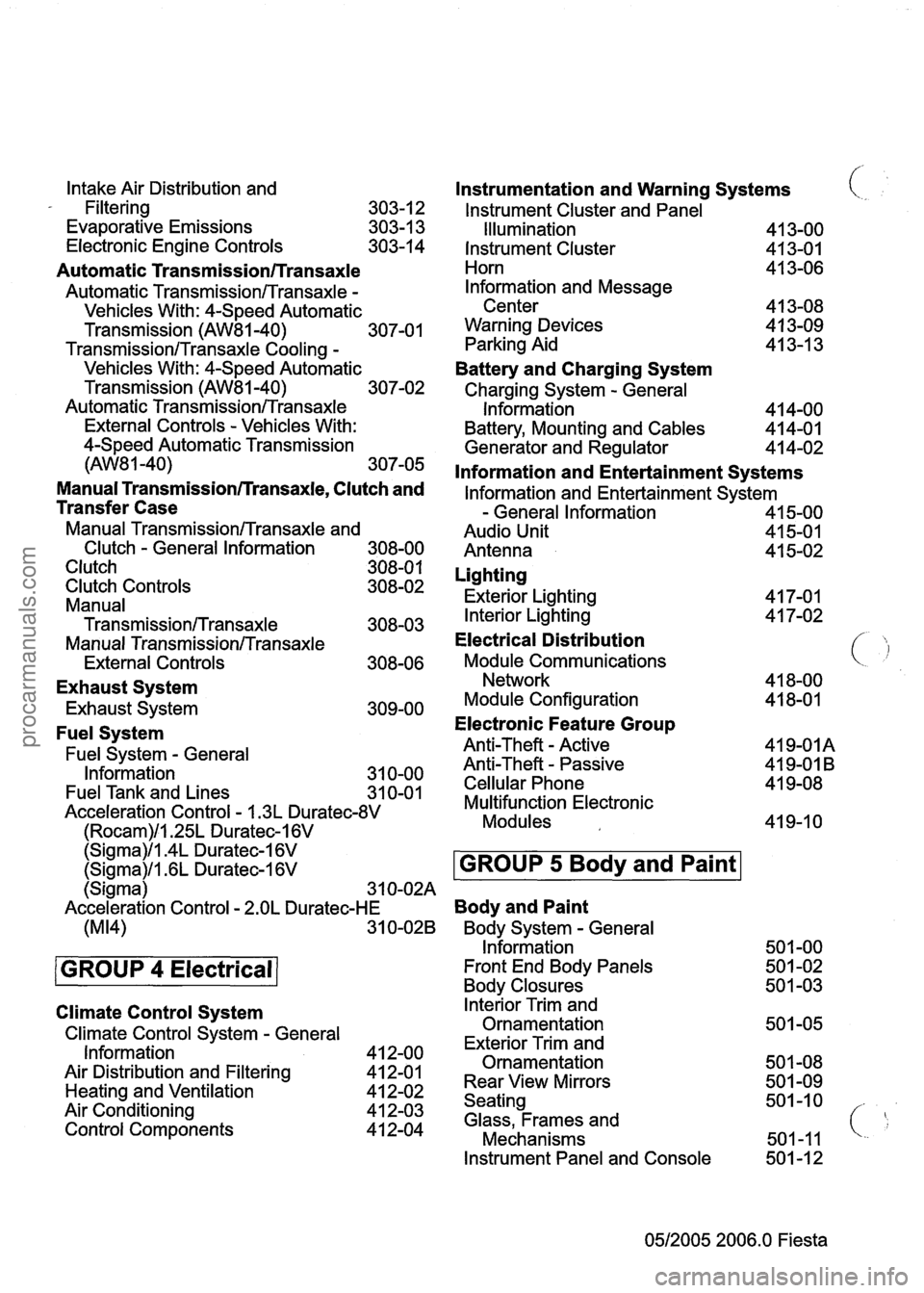
Intake Air Distribution and
- Filtering
303-1 2
Evaporative Emissions 303-1 3
Electronic Engine Controls 303-14
Automatic Transmission/Transaxle
Automatic TransmissionlTransaxle -
Vehicles With: 4-Speed Automatic
Transmission
(AW81-40) 307-01
TransmissionlTransaxle Cooling -
Vehicles With: 4-Speed Automatic
Transmission
(AW81-40) 307-02
Automatic
TransmissionlTransaxle
External Controls - Vehicles With:
4-Speed Automatic Transmission
(AW8 1 -40) 307-05
Manual Transmissionrrransaxle, Clutch and
Transfer Case
Manual TransmissionlTransaxle and
Clutch
- General Information 308-00
Clutch 308-0 1
Clutch Controls 308-02
Manual
Transmission/Transaxle 308-03
Manual TransmissionlTransaxle
External Controls 308-06
Exhaust System
Exhaust System 309-00
Fuel System
Fuel System - General
Information 31 0-00
Fuel Tank and Lines
31 0-01
Acceleration Control - I .3L Duratec-8V
(Rocam)ll.25L Duratec-I 6V
Instrumentation and Warning Systems
lnstrument Cluster and Panel
(
Illumination 41 3-00
Instrument Cluster
413-01
Horn 41 3-06
lnformation and Message
Center 41 3-08
Warning Devices
4 1 3-09
Parking Aid 41 3-1 3
Battery and Charging System
Charging System - General
Information 4 14-00
Battery, Mounting and Cables 414-01
Generator and Regulator 41 4-02
lnformation and Entertainment Systems
lnformation and Entertainment System
- General Information 41 5-00
Audio Unit 41 5-01
Antenna 41 5-02
Lighting
Exterior Lighting 41 7-01
Interior Lighting 4 1 7-02
Electrical Distribution
Module Communications ( 'j
Network 41 8-00
Module Configuration 41 8-01
Electronic Feature Group
Anti-Theft - Active 419-01A
Anti-Theft
- Passive 41 9-01 B
Cellular Phone 41 9-08
Multifunction Electronic
Modules 41 9-1 0
Climate Control System
Climate Control System - General
Information
Air Distribution and Filtering
Heating and Ventilation
Air Conditioning
Control Components
(Sigma)ll.4L Duratec-I 6V
lnterior Trim and
Ornamentation
Exterior Trim and
Ornamentation
Rear View Mirrors
Seating
Glass, Frames and
Mechanisms
(Sigma)/l .6L Duratec-1 6V
Instrument Panel and Console 501 -1 2
0512005 2006.0 Fiesta
GROUP 5 Body and Paint
(Sigma) 3 1 0-02A
Acceleration Control
- 2.OL Duratec-HE Body and Paint
(M14) 31 0-028 Body System - General
Information 501 -00
GROUP 4 Electrical Front End Body Panels 50 1 -02
Body Closures 50 1 -03
procarmanuals.com
Page 11 of 1226

GROUP
Powertrain
SECTION TITLE PAGE
Engine
Engine System . General Information ........................................................................\
.... 303-00
Enginel.25L Duratec-I 6V (Sigma)ll.4L Duratec-1 6V (Sigma)ll . 6L Duratec-I 6V
........................................................................\
.............................................. (Sigma) -303-0 I A
........................................................................\
............... Engine2.0L Duratec-HE (M14) .30 3-01 B
Engine
Cooling1.3L Duratec-8V (Rocam)ll.25L Duratec-I 6V (Sigma)ll.4L
Duratec-1 6V (Sigma)ll . 6L Duratec-1 6V (Sigma) ...................................................... .30 3-03A
Engine
Cooling2.0L Duratec-HE (M14) ........................................................................\
.. 303-038
Fuel Charging and Controlsl.25L Duratec-1 6V (Sigma)ll.4L Duratec-1 6V
........................................................................\
... (Sigma)ll . 6L Duratec-1 6V (Sigma) .30 3-0414
Fuel Charging
and Controls2.0L Duratec-HE (M14) ....................................................... 303-04B
........................................................................\
.................................... Accessory Drive .30 3-05
Starting System
........................................................................\
...................................... 303-06
Engine Ignition
........................................................................\
....................................... 303-07A
Engine Ignition2.01 Duratec-HE (M14) ........................................................................\
... 303-07B
Engine Emission
Controll.3L Duratec-8V (Rocam)ll.25L Duratec-1 6V (Sigma)ll.4L
Duratec-1 6V (Sigma)ll . 6L Duratec-1 6V (Sigma) ...................................................... .30 3-08A
Engine Emission
Control2.0L Duratec-HE (M14) ........................................................... 303-088
........................................................................\
........ Intake Air Distribution and Filtering 303-1 2
........................................................................\
.......................... Evaporative
Emissions .30 3-13
........................................................................\
.................... Electronic Engine Controls .304 3-1
Automatic Transmission/Transaxle
Automatic Transmission/TransaxleVehicles With: 4-Speed Automatic Transmission
........................................................................\
......................................... (AW8 1 .40) .301 7.0
Transmission/Transaxle CoolingVehicles With: 4-Speed Automatic Transmission
........................................................................\
.......................................... (AW81-40) 307-02
Automatic
TransmissionlTransaxle External ControlsVehicles With: 4-Speed
........................................................................\
.. Automatic Transmission (AW81-40) .30 7.05
Manual Transmission/Transaxle. Clutch and Transfer Case
Manual Transmission/Transaxle and Clutch . General Information ............................... 308-00
........................................................................\
.................................................... Clutch .301 8.0
........................................................................\
..................................... Clutch Controls .30 8.02
Manual
TransmissionlTransaxle ........................................................................\
............ 308-03
Manual
TransmissionlTransaxle External Controls ........................................................ 308-06
0512005 2006.0 Fiesta
procarmanuals.com
Page 13 of 1226
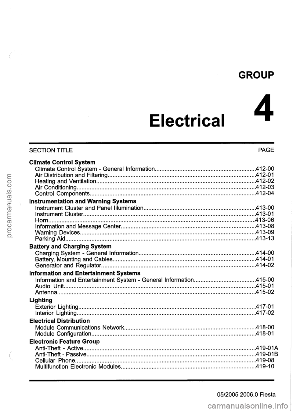
GROUP
Electrical
SECTION TITLE PAGE
Climate Control System
.......................................................... Climate Control System . General Information 42-00
........................................................................\
................... Air Distribution and Filtering 412-01
........................................................................\
......................... Heating and Ventilation .41 2-02
........................................................................\
..................................... Air Conditioning .41 2.03
........................................................................\
............................. Control Components .41 2.04
i
Instrumentation and Warning Systems
.................................................................... Instrument Cluster and Panel Illumination -41 3-00
........................................................................\
................................. Instrument Cluster .41 3-01
........................................................................\
...................................................... Horn -41 3-06
Information and Message Center ........................................................................\
........... 41 3-08
........................................................................\
................................... Warning Devices -41 3-09
........................................................................\
............................................. Parking Aid 413-1 3
Battery and Charging System
Charging System . General Information ..................................................................... 14-00
........................................................................\
............... Battery, Mounting and Cables -41 4-01
........................................................................\
...................... Generator and Regulator .41 4-02
lnformation and Entertainment Systems
Information and Entertainment System . General Information ..................................... .41 5-00
Audio Unit ........................................................................\
.............................................. 15-01
........................................................................\
................................................. Antenna .41 5-02
Lighting
........................................................................\
.................................... Exterior Lighting .41 7.01
........................................................................\
..................................... Interior Lighting -41 7-02
Electrical Distribution
........................................................................\
......... Module Communications Network 18-00
........................................................................\
............................. Module Configuration 41 8-01
Electronic Feature Group
Anti-Theft - Active ........................................................................\
.................................. 419-OIA
........................................................................\
............................... Anti-Theft . Passive .4 I 9-0 I B
........................................................................\
.............................. Cellular Phone .........4 19-08
........................................................................\
........... Multifunction Electronic Modules 41 9-1 0
0512005 2006.0
Fiesta
procarmanuals.com
Page 174 of 1226
206-00-2 Brake System - General Information 206-00-2
DESCRIPTION AND OPERATION
Brake System
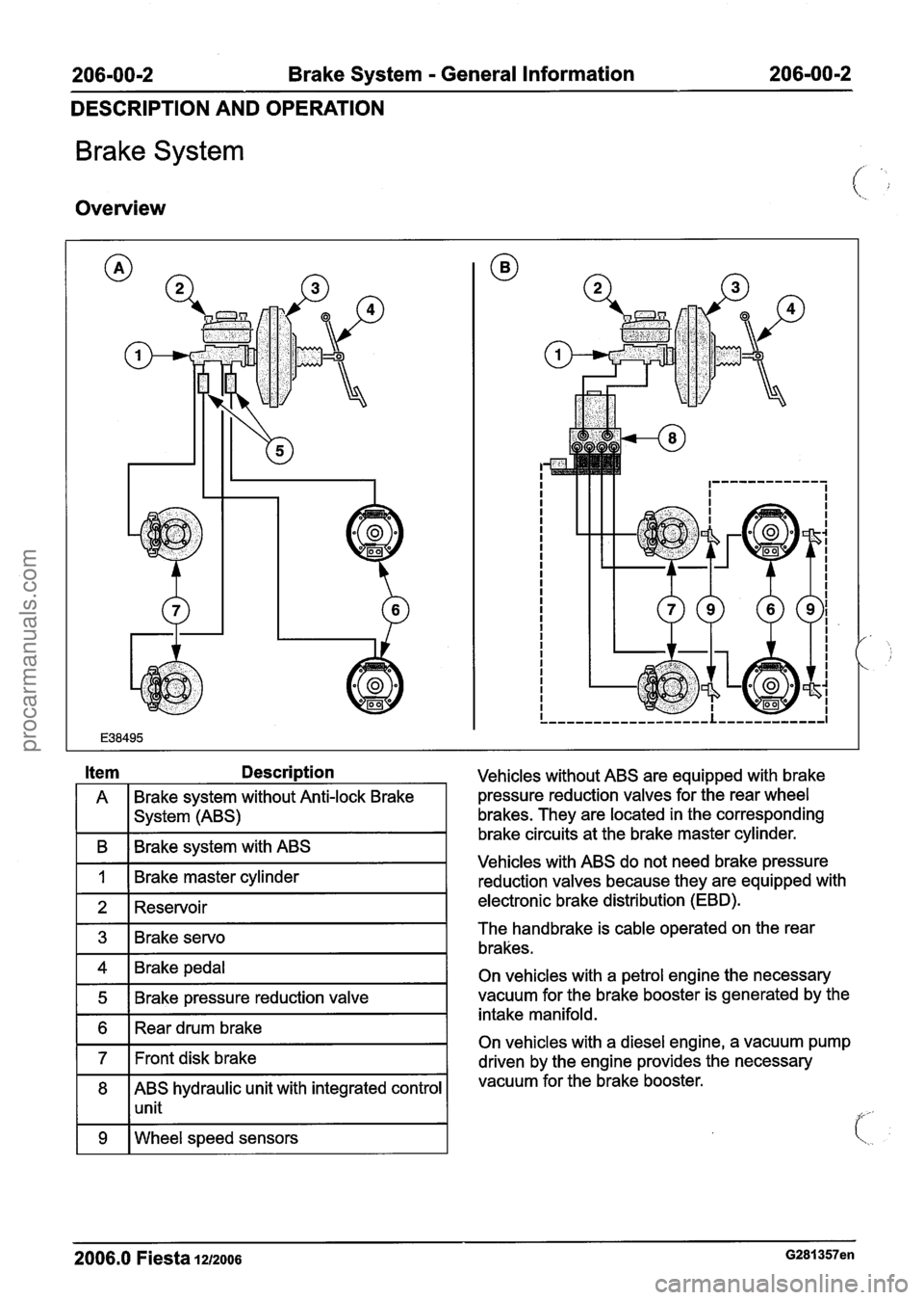
Overview
A Brake system without Anti-lock
Brake
I I system (ABS)
I B I Brake system with ABS I
I 1 I Brake master cylinder I -
1 2 1 Reservoir I
1 4 1 Brake pedal I
1 5 1 Brake pressure reduction valve I
1 6 1 Rear drum brake I
171t disk brake I
8 ABS hydraulic unit with integrated control
1 1 unit
1 9 I Wheel speed sensors I
Vehicles without ABS are equipped with brake
pressure reduction valves for the rear wheel
brakes. They are located in the corresponding
brake circuits at the brake master cylinder.
Vehicles with ABS do not need brake pressure
reduction valves because they are equipped with
electronic brake distribution (EBD).
The handbrake is cable operated on the rear
brakes.
On vehicles with a petrol engine the necessary
vacuum for the brake booster is generated by the
intake manifold.
On vehicles with a diesel engine, a vacuum pump
driven by the engine provides the necessary
vacuum for the brake booster.
2006.0 Fiesta lu2006 G281357en
procarmanuals.com
Page 277 of 1226
206-09A-3 Anti-Lock Control 206-09A-3
DESCRIPTION AND OPERATION
Anti-Lock Control
Overview
Function
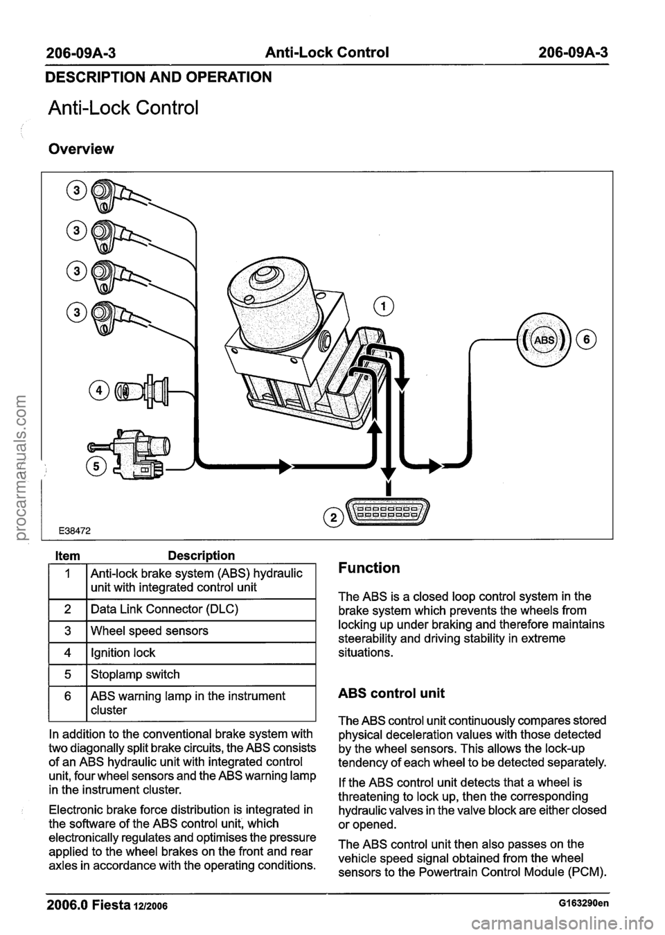
The ABS is a closed loop control system in the
brake system which prevents the wheels from
1 4 1 Ignition lock I situations.
3
1 5 1 Stoplamp switch I
6 ABS warning lamp in the instrument
I 1 cluster
Wheel
speed sensors
In addition to the conventional brake system with
two diagonally split brake circuits, the ABS consists
of an ABS hydraulic unit with integrated control
unit, four wheel sensors and the ABS warning lamp
in the instrument cluster. locking up under
braking and therefore maintains
steerability and driving stability in extreme
Electronic brake force distribution is integrated in
the software of the ABS control unit', which
electronically regulates and optimises the pressure
applied to the wheel brakes on the front and rear
axles in accordance with the operating conditions.
ABS control unit
The ABS control unit continuously compares stored
physical deceleration values with those detected
by the wheel sensors. This allows the lock-up
tendency of each wheel to be detected separately.
If the ABS control unit detects that a wheel is
threatening to lock up, then the corresponding
hydraulic valves in the valve block are either closed
or opened.
The ABS control unit then also passes on the
vehicle speed signal obtained from the wheel sensors to the Powertrain Control Module (PCM).
2006.0 Fiesta 1212oo6 GI 63290en
procarmanuals.com
Page 368 of 1226
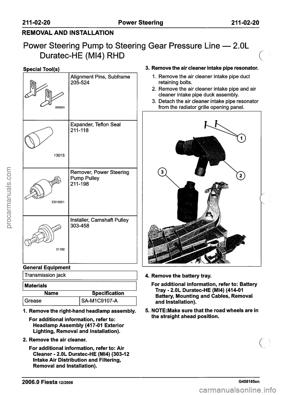
21 1-02-20 Power Steering 211 -02-20
REMOVAL AND INSTALLATION
Power Steering Pump to Steering Gear Pressure Line - 2.OL
Duratec-HE (M14) RHD
Special Tool(s)
I
- -
I Remover, Power Steering I
General Equipment 3.
Remove the air cleaner intake pipe resonator.
1. Remove the air cleaner intake pipe duct
retaining bolts.
2. Remove the air cleaner intake pipe and air
cleaner intake pipe duck assembly.
3. Detach the air cleaner intake pipe resonator
from the radiator grille opening panel.
Transmission jack
1. Remove the right-hand headlamp assembly. 5. N0TE:Make sure that the road wheels are in
For additional information, refer to: the
straight ahead position.
4.
Remove the battery tray.
Materials
Headlamp Assembly (41 7-01 Exterior
Lighting, Removal and Installation). For additional information, refer
to: Battery
2. Remove the air cleaner.
For additional information, refer to: Air
Cleaner
- 2.OL Duratec-HE (M14) (303-1 2
Intake Air Distribution and Filtering,
Removal and Installation).
Name
Specification Tray
- 2.OL Duratec-HE (M14) (414-01
Battery, Mounting and Cables, Removal
2006.0 Fiesta 1212006 G458165en
1 Grease I SA-M 1 C9 1 07-A and Installation).
procarmanuals.com
Page 430 of 1226
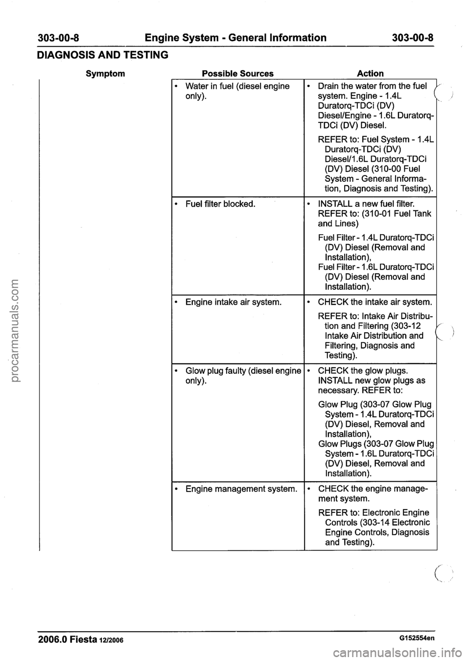
303-00-8 Engine System - General Information 303-00-8
DIAGNOSIS AND TESTING
Symptom Possible Sources Action
2006.0 Fiesta 1212006 GI 52554en
Water
in fuel (diesel engine
only).
Fuel filter blocked.
Engine intake air system.
Glow plug faulty (diesel engine
only).
Engine management system.
. Drain the water from the fuel
system. Engine
- I .4L
Duratorq-TDCi (DV)
DiesellEngine - 1.6L Duratorq-
TDCi (DV) Diesel.
REFER to: Fuel System
- I .4L
Duratorq-TDCi (DV)
Diesel11 .6L Duratorq-TDCi
(DV) Diesel (31 0-00 Fuel
System
- General Informa-
tion, Diagnosis and Testing).
INSTALL a new fuel filter.
REFER to: (31 0-01 Fuel Tank
and Lines)
Fuel Filter
- 1.4L Duratorq-TDCi
(DV) Diesel (Removal and
Installation),
Fuel Filter
- I .6L Duratorq-TDCi
(DV) Diesel (Removal and Installation).
CHECK the intake air system.
REFER to: Intake Air Distribu-
tion and Filtering (303-12
Intake Air Distribution and
Filtering, Diagnosis and
Testing).
. CHECK the glow plugs.
INSTALL new glow plugs as
necessary. REFER to:
Glow Plug (303-07 Glow Plug
System - 1.4L Duratorq-TDCi
(DV) Diesel, Removal and
Installation),
Glow Plugs (303-07 Glow Plug
System - 1.6L Duratorq-TDCi
(DV) Diesel, Removal and
Installation).
CHECK the engine manage-
ment system.
REFER to: Electronic Engine
Controls (303-1 4 Electronic Engine Controls, Diagnosis
and Testing).
procarmanuals.com
Page 432 of 1226

303-00-1 0 Engine System - General Information 303-00-1 0
DIAGNOSIS AND TESTING
Symptom
Very poor power output or fuel
consumption too high or engine
running rough
Possible Sources Action
Fuel system. CHECK the fuel system.
REFER to:
Fuel Charging and Controls
(303-04 Fuel Charging and
Controls
- 1.25L Duratec-1 6V
(Sigma)/l.4L Duratec-I 6V
(Sigma)/l.GL Duratec-1 6V
(Sigma), Diagnosis and
I Testing),
Fuel Charging and Controls
(303-04 Fuel Charging and
Controls
- 1.3L Duratec-8V
(Rocam), Diagnosis and
Testing),
Fuel Charging and Controls
(303-04 Fuel Charging and
Controls
- I .4L Duratorq-
TDCi (DV) Diesel, Diagnosis and Testing),
Fuel Charging and Controls
(303-04 Fuel Charging and
Controls
- 1.6L Duratorq-
TDCi (DV) Diesel, Diagnosis
and Testing).
Engine intake air system. CHECK the intake air system.
REFER to: lntake Air Distribu-
tion and Filtering
(303-12
lntake Air Distribution and
Filtering, Diagnosis and
Testing).
Exhaust system blocked. I CHECK the exhaust system.
REFER to: Exhaust System
(309-00 Exhaust System,
Description and Operation).
Engine management system.
CHECK the engine manage-
ment system.
REFER to: Electronic Engine
Controls (303-1 4 Electronic
Engine Controls, Diagnosis
and Testing).
Fault in ignition system (petrol
engines only). CHECK the ignition system.
REFER to:
Engine lgnition (303-07 Engine
Ignition, Diagnosis and
Testing),
Engine lgnition (303-07 Engine
lgnition
- 2.OL Duratec-HE
(M14), Diagnosis and
Testing).
2006.0 Fiesta 1212006 GI 52554en
procarmanuals.com
Page 437 of 1226
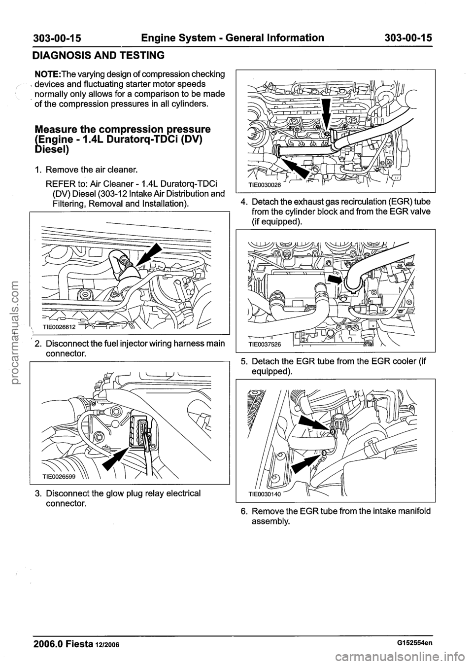
303-00-1 5 Engine System - General Information 303-00-1 5
DIAGNOSIS AND TESTING
N0TE:The varying design of compression checking
% devices and fluctuating starter motor speeds
normally only allows for a comparison to be made
of the compression pressures in all cylinders.
Measure the compression pressure
Engine
- 1.4L Duratorq-TDCi (DV)
biesel)
1. Remove the air cleaner.
REFER to: Air Cleaner
- 1.4L Duratorq-TDCi
(DV) Diesel (303-12 Intake Air Distribution and
Filtering, Removal and
Installation). 4. Detach the exhaust gas recirculation (EGR) tube
from the cylinder block and from the EGR valve
(if equipped).
I I 2. Disconnect the fuel injector wiring harness main
connector. 5. Detach the EGR tube from the EGR cooler (if
equipped).
3. Disconnect the glow plug relay electrical
connector.
6. Remove the EGR tube from the intake manifold
assembly.
2006.0 Fiesta 1212006 GI 52554en
procarmanuals.com
Page 439 of 1226
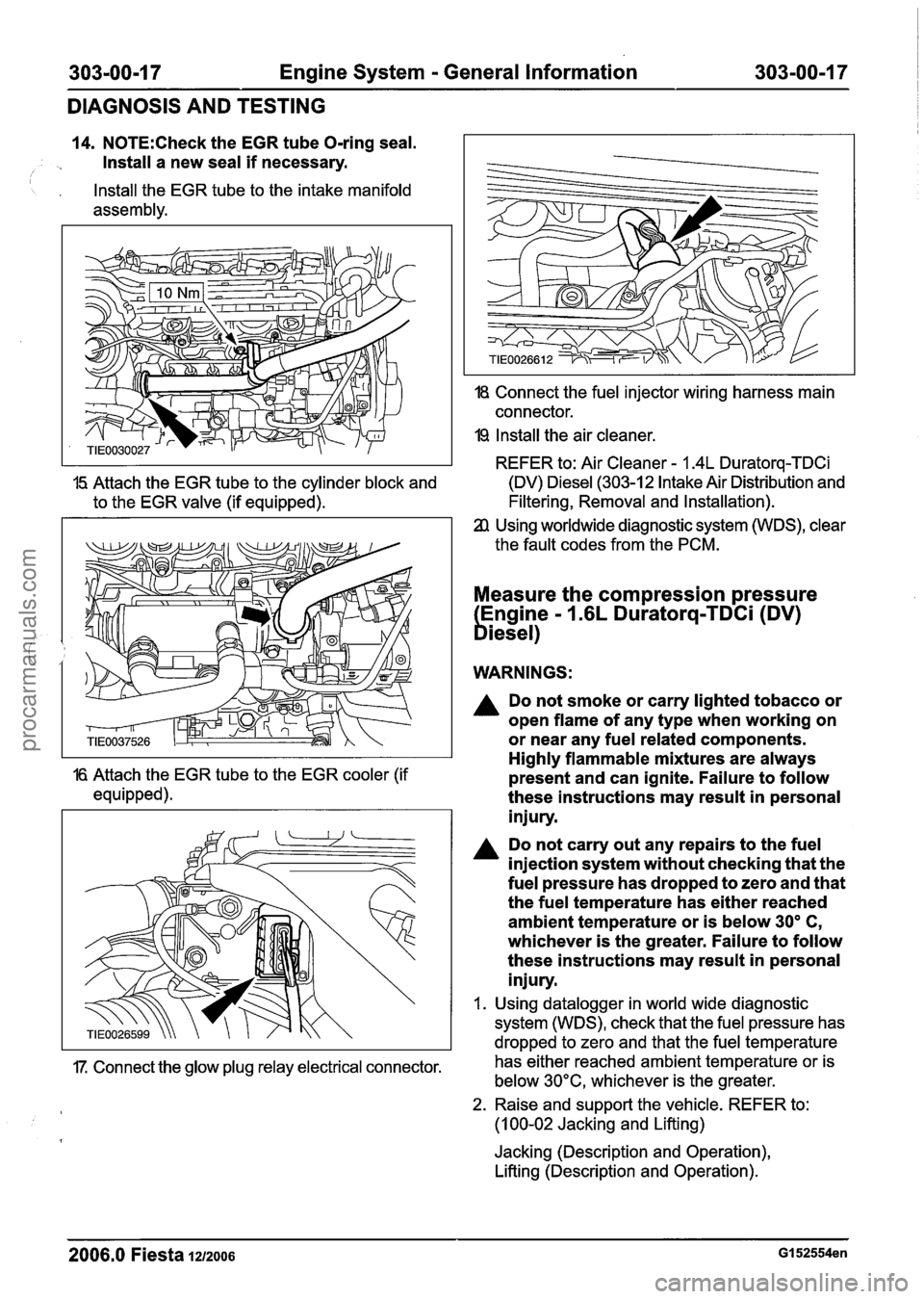
303-00-1 7 Engine System - General Information 303-00-1 7
DIAGNOSIS AND TESTING
14. N0TE:Check the EGR tube O-ring seal.
Install a new seal
if necessary. I
, Install the EGR tube to the intake manifold
assembly.
18 Connect the fuel injector wiring harness main
connector.
19 Install the air cleaner.
REFER to: Air Cleaner
- 1.4L Duratorq-TDCi
15 Attach the EGR tube to the cylinder block and (DV) Diesel (303-12 Intake Air Distribution
and
to the EGR valve (if equipped). Filtering, Removal
and Installation).
Using worldwide diagnostic system (WDS), clear
the fault codes from the PCM.
Measure the compression pressure
Engine
- 1.6L Duratorq-TDCi (DV)
biesel)
WARNINGS:
A Do not smoke or carry lighted tobacco or
open flame of any type when working on
or near any fuel related components.
Highly flammable mixtures are always
16 Attach the EGR tube to the EGR cooler (if present and can ignite. Failure to follow
equipped). these instructions may result in personal
injury.
Do not carry out any repairs to the fuel
injection system without checking that the
fuel pressure has dropped to zero and that
the fuel temperature has either reached
ambient temperature or is below
30' C,
whichever is the greater. Failure to follow
these instructions may result in personal
injury.
I. Using datalogger in world wide diagnostic
system (WDS), check that the fuel pressure has
dropped to zero and that the fuel temperature
17. Connect the glow plug relay electrical connector. has
either reached ambient temperature or is
below 30°C, whichever is the greater.
2. Raise and support the vehicle. REFER to:
(1 00-02 Jacking and Lifting)
Jacking (Description and Operation),
Lifting (Description and Operation).
2006.0 Fiesta 1212006 GI 52554en
procarmanuals.com